- Y Diweddaraf sydd Ar Gael (Diwygiedig)
- Pwynt Penodol mewn Amser (01/01/2007)
- Gwreiddiol (Fel y’i mabwysiadwyd gan yr UE)
Council Directive of 26 July 1971 on the approximation of the laws of the Member States relating to the braking devices of certain categories of motor vehicles and of their trailers (71/320/EEC) (repealed)
You are here:
- Cyfarwyddebau yn deillio o’r UE
- 1971 No. 320
- ANNEX VIII

Pa Fersiwn
Nodweddion Uwch
- Dangos Graddfa Ddaearyddol(e.e. Lloegr, Cymru, Yr Alban aca Gogledd Iwerddon)
- Dangos Llinell Amser Newidiadau
Rhagor o Adnoddau
PDF o Fersiynau Diwygiedig
- ddiwygiedig 01/11/20140.44 MB
- ddiwygiedig 01/07/20131.78 MB
- ddiwygiedig 01/01/20071.13 MB
- ddiwygiedig 01/05/20041.16 MB
- ddiwygiedig 24/10/20021.16 MB
- ddiwygiedig 07/04/19981.14 MB
- ddiwygiedig 22/08/19910.91 MB
- ddiwygiedig 30/03/19880.84 MB
- ddiwygiedig 03/01/19860.84 MB
- ddiwygiedig 24/04/19790.57 MB
- ddiwygiedig 31/07/19750.50 MB
- ddiwygiedig 20/02/19740.40 MB
- ddiwygiedig 01/01/19730.36 MB
- ddiwygiedig 30/07/19710.36 MB
Legislation originating from the EU
When the UK left the EU, legislation.gov.uk published EU legislation that had been published by the EU up to IP completion day (31 December 2020 11.00 p.m.). On legislation.gov.uk, these items of legislation are kept up-to-date with any amendments made by the UK since then.


Mae hon yn eitem o ddeddfwriaeth sy’n deillio o’r UE
Mae unrhyw newidiadau sydd wedi cael eu gwneud yn barod gan y tîm yn ymddangos yn y cynnwys a chyfeirir atynt gydag anodiadau.Ar ôl y diwrnod ymadael bydd tair fersiwn o’r ddeddfwriaeth yma i’w gwirio at ddibenion gwahanol. Y fersiwn legislation.gov.uk yw’r fersiwn sy’n weithredol yn y Deyrnas Unedig. Y Fersiwn UE sydd ar EUR-lex ar hyn o bryd yw’r fersiwn sy’n weithredol yn yr UE h.y. efallai y bydd arnoch angen y fersiwn hon os byddwch yn gweithredu busnes yn yr UE. EUR-Lex Y fersiwn yn yr archif ar y we yw’r fersiwn swyddogol o’r ddeddfwriaeth fel yr oedd ar y diwrnod ymadael cyn cael ei chyhoeddi ar legislation.gov.uk ac unrhyw newidiadau ac effeithiau a weithredwyd yn y Deyrnas Unedig wedyn. Mae’r archif ar y we hefyd yn cynnwys cyfraith achos a ffurfiau mewn ieithoedd eraill o EUR-Lex. The EU Exit Web Archive legislation_originated_from_EU_p3
Changes over time for: ANNEX VIII
Version Superseded: 01/07/2013
Status:
EU Directives are published on this site to aid cross referencing from UK legislation. Since IP completion day (31 December 2020 11.00 p.m.) no amendments have been applied to this version.
[F1ANNEX VIII U.K. Conditions governing the testing of vehicles with inertia (overrun) braking systems
Textual Amendments
1. GENERAL PROVISIONS U.K.
1.1. The ‘ inertia (overrun) braking system ’ of a trailer comprises the control device, the transmission and the brake, as defined in point 1.4. U.K.
1.2. The ‘ control device ’ is the combination of components comprising the coupling head. U.K.
1.3. The ‘ transmission ’ is the combination of components comprised between the coupling head and the first part of the brake. U.K.
1.4. The ‘ brake ’ is the part in which the forces opposing the movement of the vehicle develop. The first part of the brake is either the lever actuating the brake cam or similar parts (mechanical-transmission inertia brake) or the brake cylinder (hydraulic-transmission inertia brake). U.K.
1.5. Braking systems in which accumulated energy (for instance, electric, pneumatic or hydraulic) is transmitted to the trailer by the towing vehicle and is only controlled by the force at the coupling shall not be deemed to be inertia braking systems within the meaning of this Directive. U.K.
1.6. Tests U.K.
1.6.1. Determination of the main characteristics of the brake. U.K.
1.6.2. Determination of the main characteristics of the control device and testing as to whether that device conforms with the provisions of this Directive. U.K.
1.6.3. Testing on the vehicle: U.K.
the compatibility of the control device and the brake
the transmission.
2. SYMBOLS AND DEFINITIONS U.K.
2.1. Units used U.K.
2.1.1. Masses: kg U.K.
2.1.2. Forces: N U.K.
2.1.3. Torques and moments: Nm U.K.
2.1.4. Areas: cm 2 U.K.
2.1.5. Pressures: bar U.K.
2.1.6. Lengths: units specified in each case. U.K.
2.1.7. Acceleration due to gravity: g = 10 m/s 2 . U.K.
2.2. Symbols valid for all types of braking systems (see diagram 1 in Appendix 1) U.K.
2.2.1.
G A
:
‘ maximum mass ’ of the trailer declared to be technically permissible by the manufacturer
2.2.2.
G A
:
‘ maximum mass ’ of the trailer which, according to the manufacturer's declaration, can be braked by the control device
2.2.3.
G B
:
‘ maximum mass ’ of the trailer which can be braked by the joint operation of all the trailer brakes

2.2.4.
G Bo
:
fraction of the permissible ‘ maximum mass ’ which, according to the manufacturer's declaration, can be braked by one brake
2.2.5.
B*
:
braking force required
2.2.6.
B
:
required braking force taking account of rolling resistance
2.2.7.
D*
:
permitted thrust on coupling
2.2.8.
D
:
load on the coupling
2.2.9.
P′
:
control device output force
2.2.10.
K
:
supplementary force of control device by convention; this is defined as the force D corresponding to the point of intersection of the x axes of the extrapolated curve expressing P′ in terms of D, measured with the control system in the mid-travel position (see diagrams 2 and 3 in Appendix 1)
2.2.11.
K A
:
threshold force of control device — this is the maximum force on the coupling head which can be applied for a short period of time without producing any output force on the control device. By convention, K A is defined as the force measured when force begins to be exerted on the coupling head at a speed of from 10 to 15 mm/s, the control device transmission being uncoupled
2.2.12.
D 1
:
this is the maximum force applied to the coupling head when it is forced rearward at a speed of s mm/s ± 10 %, the transmission being uncoupled
2.2.13.
D 2
:
This is the maximum force applied to the coupling head when this is pulled forward at a speed of s mm/s ± 10 % from its rearmost position, the transmission being uncoupled
2.2.14.
ηH 0
:
efficiency of the inertia control device
2.2.15.
ηH 1
:
efficiency of the transmission system
2.2.16.

2.2.17.
s
:
travel of control (expressed in millimetres)
2.2.18.
s′
:
effective travel of control (expressed in millimetres) fixed in accordance with the requirements of point 9.4.1
2.2.19.
s″
:
spare travel of the master cylinder actuator, measured in millimetres at the coupling head
2.2.20.
s 0
:
loss of travel, that is to say the travel, measured in millimetres, of the coupling head when it is actuated in such a way as to travel from a point 300 mm above the horizontal plane to a point 300 mm below, the transmission remaining stationary
2.2.21.
2s B
:
brake-shoe lift measured on the diameter parallel to the operating mechanism and without the brakes being adjusted during the test (expressed in millimetres)
2.2.22.
2s B*
:
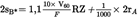
minimum brake shoe centre lift (minimum brake shoe application travel), in millimetres, for wheel brakes with drum brakes:

2r being the diameter of the brake drum expressed in millimetres (see diagram 4 in Appendix 1)
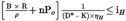
for wheel brakes with disc brakes with hydraulic transmission:
where:
V 60 = fluid volume absorption of one wheel brake at a pressure corresponding to a braking force of 1,2 1,2 B* = 0,6 × G Bo and a maximum tyre radius,
2r A = outer diameter of brake disc
(V 60 in cm 3 , F RZ in cm 2 and r A in mm)
2.2.23.
M
:
braking moment
2.2.24.
R
:
dynamic tyre rolling radius in metres, rounded to the nearest centimetre
2.2.25.
n
:
number of brakes
2.2.26.
D A
:
application force at input side of the control device, at which the overload protector is activated
2.2.27.
M A
:
braking torque at which the overload protector is activated
2.3. Symbols for mechanical transmission braking systems (see diagram 5 in Appendix 1) U.K.
2.3.1.
i H o
:
reduction ratio between travel of the coupling head and travel of the lever at the output side of the control device
2.3.2.
i H i
:
reduction ratio between travel of the lever at the output side of the control device and travel of the brake lever (gearing down of transmission)
2.3.3.

2.3.4.
i g
:
reduction ratio between travel of the brake lever and the brake-shoe centre lift (see diagram 4 in Appendix 1)
2.3.5.
P
:
force applied to the brake control lever
2.3.6.
P 0
:
brake retraction force; that is, in the graph M = ƒ (P), the value of the force P at the point of intersection of the extrapolation of this function with the abscissa (see diagram 6 in Appendix 1)
2.3.7.

2.4. Symbols for hydraulic-transmission braking systems (see diagram 8 in Appendix 1) U.K.
2.4.1.
i h
:
reduction ratio between travel of the coupling head and travel of the piston in master cylinder
2.4.2.
i g
:
reduction ratio between travel of the actuation point of the cylinders and the brake-shoe centre lift
2.4.3.
F R z
:
surface area of piston of one wheel cylinder for drum brake(s); for disc brake(s), sum of the surface area of the caliper piston(s) on one side of the disc
2.4.4.
F H z
:
surface area of piston in master cylinder
2.4.5.
p
:
hydraulic pressure in brake cylinder
2.4.6.
p O
:
retraction pressure in brake cylinder; that is, in the graph M = ƒ (p), the value of the pressure p at the point of intersection of the extrapolation of this function with the abscissa (see diagram 7 in Appendix 1)
2.4.7.

3. GENERAL REQUIREMENTS U.K.
3.1. The transmission of braking power from the coupling head to the trailer's brakes shall be effected either by a rod linkage or by means of one or more fluids. However, a sheathed cable (Bowden cable) may be used to provide part of the transmission. This part shall be as short as possible. U.K.
3.2. All pins at joints shall be adequately protected. In addition, these joints shall be either self-lubricating or easily accessible for lubrication. U.K.
3.3. Inertia braking systems shall be arranged in such a way that, in the case where the coupling head travels to its fullest extent, no part of the transmission becomes jammed, or suffers any permanent distortion or fails. This shall be checked after uncoupling the first element of the transmission from the brake control levers. U.K.
3.4. The inertia braking system shall allow the trailer to be reversed with the towing vehicle without imposing a sustained drag force exceeding 0,08 × g × G A . Devices used for this purpose shall act automatically and disengage automatically when the trailer moves forward. U.K.
3.5. Any special device incorporated for the purpose of point 3.4 shall be such that the parking performance when facing up a gradient shall not be adversely affected. U.K.
3.6. Only inertia braking systems with disc brakes may incorporate overload protectors. They may not be activated at a force of less than 1,2 P or a pressure less than 1,2 p corresponding to a braking force of B* = 0,5 × g × G B O (when fitted at the wheel brake) or at a thrust on the coupling less than 1,2 × D* (when fitted at the control device). U.K.
4. REQUIREMENTS FOR CONTROL DEVICES U.K.
4.1. The sliding members of the control device shall be long enough to enable the brake to be fully applied, even when the trailer is coupled. U.K.
4.2. The sliding members shall be protected by a bellows or some equivalent device. They shall either be lubricated or be constructed of self-lubricating materials. The surface in frictional contact shall be made of a material such that there is neither electrochemical torque nor any mechanical incompatibility liable to cause the sliding members to seize. U.K.
4.3. The threshold force of the control equipment (K A ) shall be not less than 0,02 × g × G′ A , and not more than 0,04 × g × G′ A . U.K.
4.4. The maximum damping force D 1 may not exceed 0,10 × g × G′ A in the case of trailers with rigid drawbars and 0,067 × g × G′ A in the case of multi-axled trailers with pivoted drawbars. U.K.
4.5. The maximum towing force D 2 shall be between 0,1 × g × G′ A and 0,5 × g × G′ A . U.K.
5. TESTS AND MEASUREMENTS TO BE CARRIED OUT ON THE CONTROL SYSTEM U.K.
5.1. Compliance with the requirements of points 3 and 4 shall be verified on the control device submitted to the technical service conducting the tests. U.K.
5.2. The following shall be measured in respect of all types of braking systems: U.K.
5.2.1. The travel s and the effective travel s′. U.K.
5.2.2. The supplementary force K. U.K.
5.2.3. The threshold force K A . U.K.
5.2.4. The damping force D 1 . U.K.
5.2.5. The towing force D 2 . U.K.
5.3. In the case of mechanical-transmission inertia braking systems, the following shall be determined: U.K.
5.3.1. The reduction ratio i Ho measured at the mid-travel position of the control. U.K.
5.3.2. The force P′ at the output side of the control device as a function of the thrust D on the drawbar. The supplementary force K and the efficiency shall be derived from the representative curve obtained from these measurements. U.K.

(see diagram 2 in Appendix 1).
5.4. In the case of hydraulic-transmission inertia braking systems, the following shall be determined: U.K.
5.4.1. The reduction ratio i h measured at the mid-travel position of the control. U.K.
5.4.2. The pressure p at the output side of the master cylinder as a function of the thrust D on the drawbar and of the surface area F HZ of the master cylinder piston, as specified by the manufacturer. The supplementary force K and the efficiency shall be derived from the representative curve obtained from these measurements U.K.

(see diagram 3 in Appendix 1).
5.4.3. The spare travel of the master cylinder actuator s″ mentioned in point 2.2.19. U.K.
5.5. In the case of inertia braking systems on multi-axled trailers with pivoted drawbars, the loss of travel s O mentioned in point 9.4.1 shall be measured. U.K.
6. REQUIREMENTS FOR BRAKES U.K.
6.1. The manufacturer shall make available to the technical service responsible for the tests, in addition to the brakes to be tested, drawings of the brakes showing the type, dimensions and material of the main parts, and the make and type of the linings. These drawings shall indicate the surface area F RZ of the brake cylinders in the case of hydraulic brakes. The manufacturer shall also indicate the maximum braking torque M max which is allowed, as well as the mass G BO mentioned in point 2.2.4. U.K.
6.2. The braking torque M max specified by the manufacturer shall be not less than that braking torque corresponding to 1,2 times the force P or 1,2 times the pressure p, required to give a braking force of B* = 0,5 × g × G BO . U.K.
6.2.1. In the case when no overload protector is either fitted or intended to be fitted within the inertia (overrun) braking system, the wheel brake shall be tested at 1,8 times the force P or at 1,8 times the pressure p, which is required to give a braking force of B* = 0,5 × g × G BO . U.K.
6.2.2. In the case when an overload protector is fitted or intended to be fitted within the inertia (overrun) braking system, the wheel brake shall be tested at 1,1 times the force P max or P′ max or at 1,1 times the pressure pmax or p′max of the overload protector including all tolerances (specified by the manufacturer). U.K.
7. TESTS AND MEASUREMENTS TO BE CARRIED OUT ON THE BRAKES U.K.
7.1. The brakes and items of equipment made available to the technical service responsible for the tests shall be tested to check whether they conform to the requirements of point 6. U.K.
7.2. The following shall be determined: U.K.
7.2.1. The minimum shoe centre lift 2s B *. U.K.
7.2.2. The shoe centre lift 2s B (which shall be greater than 2s B *). U.K.
7.2.3. The braking moment M as a function of the force P applied to the control lever in the case of devices with mechanical transmission, and of the pressure p in the brake cylinder in the case of devices with hydraulic transmission. U.K.
The speed at which the braking surfaces rotate shall correspond to an initial vehicle speed of 60 km/h. The following is deduced from the curve obtained from these measurements:
7.2.3.1. The retraction force P O and the characteristic ρ in the case of mechanically actuated brakes (see diagram 6 in Appendix 1). U.K.
7.2.3.2. The retraction pressure p o and the characteristic ρ′ in the case of hydraulically actuated brakes (see diagram 7 in Appendix 1). U.K.
8. TEST REPORTS U.K.
Where applications are made for type-approval of trailers fitted with inertia braking systems, such applications are to be accompanied by the test reports relating to the control system and the brakes, as well as the test report on the compatibility between the inertia control device, the transmission and the brakes on the trailer; these reports are to include at least the particulars shown in Appendices 2, 3 and 4 to this Annex.
9. COMPATIBILITY OF THE CONTROL DEVICE AND THE BRAKES OF A VEHICLE U.K.
9.1. A check shall be made on the vehicle, taking into account the characteristics of the control device (Appendix 2) and of the brakes (Appendix 3) as well as the trailer characteristics mentioned in point 4 of Appendix 4, as to whether the inertia braking system of the trailer complies with the requirements laid down. U.K.
9.2. General tests for all types of brakes U.K.
9.2.1. Those parts of the transmission which have not been tested at the same time as the brake control device or the brakes shall be tested on the vehicle. The results of the test shall be entered in Appendix 4 (for example i H1 and η H1 ). U.K.
9.2.2. Mass U.K.
9.2.2.1. The maximum mass of the trailer G A shall not exceed the maximum mass G′ A for which the control device is authorised. U.K.
9.2.2.2. The maximum mass of the trailer G A shall not exceed the maximum mass G B which can be braked by the joint operation of all the trailer brakes. U.K.
9.2.3. Forces U.K.
9.2.3.1. The threshold force K A shall not be less than 0,02 × g × G A nor greater than 0,04 × g × G A . U.K.
9.2.3.2. The maximum damping force D 1 shall not exceed 0,10 × g × G A in the case of trailers with rigid drawbars, nor 0,067 × g × G A in the case of multi-axled trailers with pivoted drawbars. U.K.
9.2.3.3. The maximum towing force D 2 shall be between 0,1 × g × G A and 0,5 × g × G A . U.K.
9.3. Test of braking efficiency U.K.
9.3.1. The sum of the braking forces exerted on the circumference of the trailer wheels shall be at least B* = 0,5 × g × G A including a rolling resistance of 0,01 × g × G A . This represents a braking force of B = 0,49 × g × G A . In this case, the maximum permitted thrust on the coupling is: U.K.
D*
=
0,067 × g × G A in the case of multi-axled trailers with pivoting drawbars, and
D*
=
0,10 × g × G A in the case of trailers with rigid drawbars.
In order to check whether these conditions are observed, the following inequalities shall be applied:
9.3.1.1. In the case of inertia braking systems with mechanical transmission U.K.
9.3.1.2. In the case of inertia braking systems with hydraulic transmission U.K.

9.4. Control travel test U.K.
9.4.1. In the case of control devices for multi-axle trailers with pivoted drawbars, of which the brake rod system is dependent upon the position of the towing device, the travel of the control s shall be greater than the effective travel of the control s′; the difference in length shall be at least equivalent to the loss of travel s o . The travel s o shall not exceed 10 % of the effective travel s′. U.K.
9.4.2. The effective travel of the control s′ shall be determined in the following way: U.K.
9.4.2.1. If the brake rod system is affected by the relative position of the towing device, then U.K.

9.4.2.2. If there is no loss of travel, then U.K.

9.4.2.3. In the case of hydraulic braking systems U.K.

9.4.3. The following inequalities shall be applied in order to check whether the travel of the control is adequate: U.K.
9.4.3.1. In the case of inertia braking systems with mechanical transmission: U.K.

9.4.3.2. In the case of inertia braking systems with hydraulic transmission: U.K.

9.5. Additional tests U.K.
9.5.1. In the case of inertia braking systems with mechanical transmission, a check shall be made as to whether the rod system by which the forces are transmitted from the control device is correctly fitted. U.K.
9.5.2. In the case of inertia braking systems with hydraulic transmission, a check shall be made as to whether the travel of the master cylinder actuator reaches a minimum level of s/i h . U.K.
A lower level shall not be permitted.
9.5.3. The general behaviour of the vehicle when braking shall be the subject of a road test carried out at different speeds, with different levels of brake effort and rates of application; self-excited undamped oscillations shall not be permitted. U.K.
10. GENERAL COMMENTS U.K.
The above provisions apply to the latest models of inertia braking systems with mechanical or hydraulic transmission; in the case of these models, in particular, all the wheels of the trailer are fitted with the same type of brake and the same type of tyre.
When testing special models, the above requirements shall be adapted.
Appendix 1 Explanatory diagrams
Diagram 1 U.K. Symbols valid for all types of braking systems U.K. (see point 2.2) U.K.

Diagram 2 U.K. Mechanical transmission U.K. (see points 2.2.10 and 5.3.2) U.K.

Diagram 3 U.K. Hydraulic transmission U.K. (see points 2.2.10 and 5.4.2) U.K.

Diagram 4 U.K. Brake checks U.K. (see points 2.2.22 and 2.3.4) U.K.

Brake-shoe centre lift: S B * = 1,2 mm + 0,2 % × 2r

Diagram 5 U.K. Brakes with mechanical transmission U.K. (see point 2.3) U.K.

Diagram 6 U.K. Mechanical brake U.K. (see points 2.3.6 and 7.2.3.1) U.K.

Diagram 7 U.K. Hydraulic brake U.K. (see points 2.4.6 and 7.2.3.2) U.K.

Diagram 8 U.K. Hydraulic transmission braking system U.K. (see point 2.4) U.K.

Appendix 2 Test report on the control device


Appendix 3 Test report on the brake

Appendix 4 Test report on the compatibility of the control device, the transmission and the brakes]


Options/Help
Print Options
PrintThe Whole Directive
PrintThis Annex only
You have chosen to open the Whole Directive
The Whole Directive you have selected contains over 200 provisions and might take some time to download. You may also experience some issues with your browser, such as an alert box that a script is taking a long time to run.
Would you like to continue?
You have chosen to open Schedules only
Y Rhestrau you have selected contains over 200 provisions and might take some time to download. You may also experience some issues with your browser, such as an alert box that a script is taking a long time to run.
Would you like to continue?
Mae deddfwriaeth ar gael mewn fersiynau gwahanol:
Y Diweddaraf sydd Ar Gael (diwygiedig):Y fersiwn ddiweddaraf sydd ar gael o’r ddeddfwriaeth yn cynnwys newidiadau a wnaed gan ddeddfwriaeth ddilynol ac wedi eu gweithredu gan ein tîm golygyddol. Gellir gweld y newidiadau nad ydym wedi eu gweithredu i’r testun eto yn yr ardal ‘Newidiadau i Ddeddfwriaeth’.
Gwreiddiol (Fel y’i mabwysiadwyd gan yr UE): Mae'r wreiddiol version of the legislation as it stood when it was first adopted in the EU. No changes have been applied to the text.
Pwynt Penodol mewn Amser: This becomes available after navigating to view revised legislation as it stood at a certain point in time via Advanced Features > Show Timeline of Changes or via a point in time advanced search.
Gweler y wybodaeth ychwanegol ochr yn ochr â’r cynnwys
Rhychwant ddaearyddol: Indicates the geographical area that this provision applies to. For further information see ‘Frequently Asked Questions’.
Dangos Llinell Amser Newidiadau: See how this legislation has or could change over time. Turning this feature on will show extra navigation options to go to these specific points in time. Return to the latest available version by using the controls above in the What Version box.
Dewisiadau Agor
Dewisiadau gwahanol i agor deddfwriaeth er mwyn gweld rhagor o gynnwys ar y sgrin ar yr un pryd
Rhagor o Adnoddau
Gallwch wneud defnydd o ddogfennau atodol hanfodol a gwybodaeth ar gyfer yr eitem ddeddfwriaeth o’r tab hwn. Yn ddibynnol ar yr eitem ddeddfwriaeth sydd i’w gweld, gallai hyn gynnwys:
- y PDF print gwreiddiol y fel adopted version that was used for the EU Official Journal
- rhestr o newidiadau a wnaed gan a/neu yn effeithio ar yr eitem hon o ddeddfwriaeth
- pob fformat o’r holl ddogfennau cysylltiedig
- slipiau cywiro
- dolenni i ddeddfwriaeth gysylltiedig ac adnoddau gwybodaeth eraill
Llinell Amser Newidiadau
Mae’r llinell amser yma yn dangos y fersiynau gwahanol a gymerwyd o EUR-Lex yn ogystal ag unrhyw fersiynau dilynol a grëwyd ar ôl y diwrnod ymadael o ganlyniad i newidiadau a wnaed gan ddeddfwriaeth y Deyrnas Unedig.
Cymerir dyddiadau fersiynau’r UE o ddyddiadau’r dogfennau ar EUR-Lex ac efallai na fyddant yn cyfateb â’r adeg pan ddaeth y newidiadau i rym ar gyfer y ddogfen.
Ar gyfer unrhyw fersiynau a grëwyd ar ôl y diwrnod ymadael o ganlyniad i newidiadau a wnaed gan ddeddfwriaeth y Deyrnas Unedig, bydd y dyddiad yn cyd-fynd â’r dyddiad cynharaf y daeth y newid (e.e. ychwanegiad, diddymiad neu gyfnewidiad) a weithredwyd i rym. Am ragor o wybodaeth gweler ein canllaw i ddeddfwriaeth ddiwygiedig ar Ddeall Deddfwriaeth.
Rhagor o Adnoddau
Defnyddiwch y ddewislen hon i agor dogfennau hanfodol sy’n cyd-fynd â’r ddeddfwriaeth a gwybodaeth am yr eitem hon o ddeddfwriaeth. Gan ddibynnu ar yr eitem o ddeddfwriaeth sy’n cael ei gweld gall hyn gynnwys:
- y PDF print gwreiddiol y fel adopted fersiwn a ddefnyddiwyd am y copi print
- slipiau cywiro
liciwch ‘Gweld Mwy’ neu ddewis ‘Rhagor o Adnoddau’ am wybodaeth ychwanegol gan gynnwys
- rhestr o newidiadau a wnaed gan a/neu yn effeithio ar yr eitem hon o ddeddfwriaeth
- manylion rhoi grym a newid cyffredinol
- pob fformat o’r holl ddogfennau cysylltiedig
- dolenni i ddeddfwriaeth gysylltiedig ac adnoddau gwybodaeth eraill
 Mae’r holl gynnwys ar gael dan Drwydded Llywodraeth Agored v3.0 ac eithrio ble nodir yn wahanol. Yn ychwanegol mae’r safle hwn â chynnwys sy’n deillio o EUR-Lex, a ailddefnyddiwyd dan delerau Penderfyniad y Comisiwn 2011/833/EU ar ailddefnyddio dogfennau o sefydliadau’r UE. Am ragor o wybodaeth gweler ddatganiad cyhoeddus Swyddfa Gyhoeddiadau’r UE ar ailddefnyddio.