- Latest available (Revised)
- Original (As adopted by EU)
Commission Implementing Regulation (EU) 2016/799Show full title
Commission Implementing Regulation (EU) 2016/799 of 18 March 2016 implementing Regulation (EU) No 165/2014 of the European Parliament and of the Council laying down the requirements for the construction, testing, installation, operation and repair of tachographs and their components (Text with EEA relevance)
You are here:

What Version
Advanced Features
- Show Geographical Extent(e.g. England, Wales, Scotland and Northern Ireland)
- Show Timeline of Changes
More Resources
Revised version PDFs
- Revised 26/02/202011.25 MB
- Revised 17/04/201810.62 MB
- Revised 26/05/20169.89 MB
This is a Regulation originating from the EU


This is a legislation item that originated from the EU
After exit day there will be three versions of this legislation to consult for different purposes. The legislation.gov.uk version is the version that applies in the UK. The EU Version currently on EUR-lex is the version that currently applies in the EU i.e you may need this if you operate a business in the EU.
The web archive version is the official version of this legislation item as it stood on exit day before being published to legislation.gov.uk and any subsequent UK changes and effects applied. The web archive also captured associated case law and other language formats from EUR-Lex.
Changes over time for: Division 5.4
Changes to legislation:
There are outstanding changes not yet made to Commission Implementing Regulation (EU) 2016/799. Any changes that have already been made to the legislation appear in the content and are referenced with annotations.
Changes to Legislation
Revised legislation carried on this site may not be fully up to date. Changes and effects are recorded by our editorial team in lists which can be found in the ‘Changes to Legislation’ area. Where those effects have yet to be applied to the text of the legislation by the editorial team they are also listed alongside the legislation in the affected provisions. Use the ‘more’ link to open the changes and effects relevant to the provision you are viewing.
Changes and effects yet to be applied to the whole legislation item and associated provisions
- Signature words omitted by S.I. 2019/453 reg. 110
- Annex 1C modified by S.I. 2023/739 reg. 3 Sch.
5.4 DSRC Protocol requirements for RTM U.K.
5.4.1 Overview U.K.
DSC_34The transaction protocol to download the Data across the 5.8 GHz DSRC interface link shall be according to the following steps. This section describes a transaction flow under ideal conditions without retransmissions or communication interrupts.U.K.
NOTE The purpose of the initialisation phase (Step 1) is to set up the communication between the REDCR and DSRC-VUs that have entered the 5.8 GHz DSRC (master-slave) transaction zone but have not yet established communication with the REDCR, and to notify the application processes.U.K.
— Step 1
Initialisation. The REDCR sends a frame containing a ‘beacon service table’ (BST) that includes the application identifiers (AIDs) in the service list that it supports. In the RTM application this will simply be the service with the AID value = 2 (Freight&Fleet). The DSRC-VU evaluates the received BST, and shall respond (see below) with the list of the supported applications within the Freight&Fleet domain, or shall not respond if none are supported. If the REDCR does not offer AID=2, the DSRC-VU shall not answer to the REDCR.
— Step 2
The DSRC-VU sends a frame containing a request for a private window allocation.
— Step 3
The REDCR sends a frame containing a private window allocation.
— Step 4
The DSRC-VU uses the allocated private window to send a frame containing its vehicle service table (VST). This VST includes a list of all the different application instantiations that this DSRC-VU supports in the framework of AID=2. The different instantiations shall be identified by means of uniquely generated EIDs, each associated with an Application Context Mark parameter value indicating the application and standard supported.
— Step 5
Next the REDCR analyses the offered VST, and either terminates the connection (RELEASE) since it is not interested in anything the VST has to offer (i.e. it is receiving a VST from a DSRC-VU that is not supporting the RTM transaction), or, if it receives an appropriate VST it starts an app instantiation.
— Step 6
To bring this about, the REDCR shall send a frame containing a command to retrieve the RTM data, identifying the RTM application instantiation by specifying the identifier corresponding to the RTM application instantiation (as specified by the DSRC-VU in the VST), and shall allocate a private window.
— Step 7
The DSRC-VU uses the newly allocated private window to send a frame that contains the addressed identifier corresponding to the RTM application instantiation as provided in the VST, followed by the attribute RtmData (payload element + security element).
— Step 8
If there are multiple services requested, the value ‘n’ is changed to the next service reference number and the process repeated.
— Step 9
The REDCR confirms receipt of the data by sending a frame containing a RELEASE command to the DSRC-VU to terminate the session OR if it has failed to validate a successful receipt of the LDPU goes back to step 6.
See Figure 14.6 for a pictorial description of the transaction protocol.

5.4.2 Commands U.K.
DSC_35The following commands are the only functions used in an RTM transaction phaseU.K.
— INITIALISATION.request
:
A command, issued from the REDCR in the form of a broadcast with definition of applications that the REDCR supports.
— INITIALISATION.response
:
An answer from the DSRC-VU confirming the connection and containing a list of supported application instances with characteristics and information how to address them (EID).
— GET.request
:
A command, issued from the REDCR to the DSRC-VU, that specifies the application instantiation to be addressed by means of a defined EID, as received in the VST, instructing the DSRC-VU to send the selected attribute(s) with the Data. The objective of the GET command is for the REDCR to obtain the Data from the DSRC-VU.
— GET.response
:
An answer from the DSRC-VU that contains the Data requested.
— ACTION.request ECHO
:
A command, instructing the DSRC-VU to send back data from the DSRC-VU to the REDCR. The objective of the ECHO command is to enable workshops or type approval test facilities to test that the DSRC link is working without needing access to security credentials.
— ACTION.response ECHO
:
An answer from the DSRC VU on the ECHO command.
— EVENT_REPORT.request RELEASE
:
A command, instructing the DSRC-VU that the transaction is ended. The objective of the RELEASE command is to end the session with the DSRC-VU. On receipt of the RELEASE the DSRC-VU shall not respond to any further interrogations under the current connection. Note that according to EN 12834 a DSRC-VU will not connect twice to the same interrogator unless it has been out of the communication zone for 255 seconds or if the Beacon ID of the interrogator is changed.
5.4.3 Interrogation command sequence U.K.
DSC_36From the perspective of the command and response sequence, the transaction is described as follows:U.K.
| Sequence | Sender | Receiver | Description | Action | |
|---|---|---|---|---|---|
| 1 | REDCR | > | DSRC-VU | Initialisation of the communication link — Request | REDCR broadcasts BST |
| 2 | DSRC-VU | > | REDCR | Initialisation of the communication link — Response | If BST supports AID=2 then DSRC-VU Requests a private window |
| 3 | REDCR | > | DSRC-VU | Grants a private window | Sends Frame containing private window allocation |
| 4 | DSRC-VU | > | REDCR | Sends VST | Sends Frame comprising VST |
| 5 | REDCR | > | DSRC-VU | Sends GET.request for data in Attribute for specific EID | |
| 6 | DSRC-VU | > | REDCR | Sends GET.response with requested Attribute for specific EID | Sends Attribute (RTMData, OWSData….) with data for specific EID |
| [F17 | REDCR | > | DSRC-VU | Sends GET.request for data of other Attribute (if appropriate) | ] |
| 8 | DSRC-VU | > | REDCR | Sends GET.response with requested Attribute | Sends Attribute with data for specific EID |
| 9 | REDCR | > | DSRC-VU | Acknowledges successful receipt of data | Sends RELEASE command which closes transaction |
| 10 | DSRC-VU | Closes transaction |
An example of the transaction sequence and contents of the exchanged frames is defined in clauses 5.4.7 and 5.4.8
5.4.4 Data structures U.K.
DSC_37The semantic structure of the Data when passed across the 5.8 GHz DSRC interface shall be consistent with what described in this Appendix. The way these data are structured is specified in this clause.U.K.
DSC_38The payload (RTM data) consists of the concatenation ofU.K.
1.
EncryptedTachographPayload data, which is the encryption of the TachographPayload defined in ASN.1 in section 5.4.5. The method of encryption is described in Appendix 11
2.
DSRCSecurityData, specified in Appendix 11.
DSC_39The RTM Data is being addressed as RTM Attribute=1 and is transferred in the RTM container = 10.U.K.
DSC_40The RTM Context Mark shall identify the supported standard part in the TARV series of standards (RTM corresponds to Part 9)U.K.
The ASN.1 module definition for the DSRC data within the RTM application is defined as follows:


5.4.5 Elements of RtmData, actions performed and definitions U.K.
DSC_41The data values to be calculated by the VU and used to update the secured data in the DSRC-VU shall be calculated according to the rules defined in Table 14.3:U.K.
| Table 14.3 | |||
| Elements of RtmData, actions performed and definitions | |||
| (1) RTM Data Element | (2) Action performed by the VU | (3) ASN.1 definition of data | |
|---|---|---|---|
| RTM1 Vehicle Registration Plate | The VU shall set the value of the tp15638VehicleRegistrationPlate data element RTM1 from the recorded value of the data type VehicleRegistrationIdentification as defined in Appendix 1 VehicleRegistrationIdentification | Vehicle Registration Plate expressed as a string of characters | 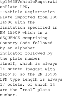 |
| RTM2 Speeding Event | The VU shall generate a boolean value for data element RTM2 tp15638SpeedingEvent. The tp15638SpeedingEvent value shall be calculated by the VU from the number of Over Speeding Events recorded in the VU in the last 10 days of occurrence, as defined in Annex 1C. If there is at least one tp15638SpeedingEvent in the last 10 days of occurrence, the tp15638SpeedingEvent value shall be set to TRUE. ELSE if there are no events in the last 10 days of occurrence, the tp15638SpeedingEvent shall be set to FALSE. | 1 (TRUE) — Indicates irregularities in speed within last 10 days of occurrence |  |
| RTM3 Driving Without Valid Card | The VU shall generate a boolean value for data element RTM3 tp15638DrivingWithoutValidCard. The VU shall assign a value of True to the tp15638DrivingWithoutValidCard variable if the VU data has recorded at least one event in the last 10 days of occurrence of type ‘Driving without an appropriate card’ event as defined in Annex 1C. ELSE if there are no events in the last 10 days of occurrence, the tp15638DrivingWithoutValidCard variable shall be set to FALSE. | 1 (TRUE) = Indicates invalid card usage |  |
| RTM4 Valid Driver Card | The VU shall generate a boolean value for data element RTM4 tp15638DriverCard on the basis of the data stored in the VU and defined in Appendix 1. If no valid driver card is present the VU shall set the variable to TRUE ELSE if a valid driver card is present the VU shall set the variable to FALSE | 0 (FALSE) = Indicates a valid driver card |  |
| RTM5 Card Insertion while Driving | The VU shall generate a boolean value for data element RTM5. The VU shall assign a value of TRUE to the tp15638CardInsertion variable if the VU data has recorded in the last 10 days of occurrence at least one event of type ‘Card insertion while driving.’ as defined in Annex 1C. ELSE if there are no such events in the last 10 days of occurrence, the tp15638CardInsertion variable shall be set to FALSE. | 1 (TRUE) = Indicates card insertion while driving within last 10 days of occurrence | 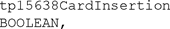 |
| RTM6 Motion Data Error | The VU shall generate a boolean value for data element RTM6. The VU shall assign a value of TRUE to the tp15638MotionDataError variable if the VU data has in the last 10 days of occurrence recorded at least one event of type ‘Motion data error’ as defined in Annex 1C. ELSE if there are no such events in the last 10 days of occurrence, the tp15638MotionDataError variable shall be set to FALSE. | 1 (TRUE) = Indicates motion data error within last 10 days of occurrence |  |
| RTM7 Vehicle Motion Conflict | The VU shall generate a boolean value for data element RTM7. The VU shall assign a value of TRUE to the tp15638vehicleMotionConflict variable if the VU data has in the last 10 days recorded at least one event of type Vehicle Motion Conflict (value ‘0A’H ). ELSE if there are no events in the last 10 days of occurrence, the tp15638vehicleMotionConflict variable shall be set to FALSE. | 1 (TRUE) = Indicates motion conflict within last 10 days of occurrence |  |
| RTM8 2nd Driver Card | The VU shall generate a boolean value for data element RTM8 on the basis of Annex 1C (‘Driver Activity Data’ CREW and CO-DRIVER). If a 2nd valid driver card is present the VU shall set the variable to TRUE ELSE if a 2nd valid driver card is not present the VU shall set the variable to FALSE | 1 (TRUE) = Indicates a second driver card inserted |  |
| RTM9 Current Activity | The VU shall generate a boolean value for data element RTM9. If the current activity is recorded in the VU as any activity other than ‘DRIVING’ as defined in Annex 1C the VU shall set the variable to TRUE ELSE if the current activity is recorded in the VU as ‘DRIVING’ the VU shall set the variable to FALSE | 1 (TRUE) = other activity selected; 0 (FALSE) = driving selected |  |
| RTM10 Last Session Closed | The VU shall generate a boolean value for data element RTM10. If the last card session was not properly closed as defined in Annex 1C the VU shall set the variable to TRUE. ELSE if the last card session was properly closed the VU shall set the variable to FALSE | 1 (TRUE) = improperly closed 0 (FALSE) = properly closed |  |
| RTM11 Power Supply Interruption | The VU shall generate an integer value for data element RTM11. The VU shall assign a value for the tp15638PowerSupplyInterruption variable equal to the longest power supply interruption according to Article 9, Reg (EU) 165/2014 of type ‘Power supply interruption’ as defined in Annex 1C. ELSE if in the last 10 days of occurrence there are have been no Power supply interruption events the value of the integer shall be set to 0. | —Number of power supply interruptions in last 10 days of occurrence |  |
| [F1RTM12 Sensor Fault | The VU shall generate an integer value for data element RTM12. The VU shall assign to the variable sensorFault a value of:
| – sensor fault one octet as per data dictionary |  ] ] |
| RTM13 Time Adjustment | The VU shall generate an integer value (timeReal from Appendix 1) for data element RTM13 on the basis of the presence of Time Adjustment data as defined in Annex 1C. The VU shall assign the value of time at which the last time adjustment data event has occurred. ELSE if no ‘Time Adjustment’ event. as defined in Annex 1C is present in the VU data it shall set a value of 0 | Time of the last time adjustment |  |
| RTM14 Security Breach Attempt | The VU shall generate an integer value (timeReal from Appendix 1) for data element RTM14 on the basis of the presence of a Security breach attempt event as defined in Annex 1C. The VU shall set the value of the time of the latest security breach attempt event recorded by the VU. ELSE if no ‘security breach attempt’ event as defined in Annex 1C is present in the VU data it shall set a value of 0x00FF. | Time of last breach attempt —Default value =0x00FF |  |
| RTM15 Last Calibration | The VU shall generate an integer value (timeReal from Appendix 1) for data element RTM15 on the basis of the presence of Last Calibration data as defined in Annex 1C. The VU shall set the value of time of the latest two calibrations (RTM15 and RTM16), which are set in VuCalibrationData defined in Appendix 1. The VU shall set the value for RTM15 to the timeReal of the latest calibration record. | Time of last calibration data |  |
| RTM16 Previous Calibration | The VU shall generate an integer value (timeReal from Appendix 1) for data element RTM16 of the calibration record preceding that of the last calibration ELSE if there has been no previous calibration the VU shall set the value of RTM16 to 0. | Time of previous calibration data |  |
| RTM17 Date Tachograph Connected | For data element RTM17 the VU shall generate an integer value (timeReal from Appendix 1). The VU shall set the value of the time of the initial installation of the VU. The VU shall extract this data from the VuCalibrationData (Appendix 1) from the vuCalibrationRecords with CalibrationPurpose equal to: ‘03’H | Date tachograph connected | 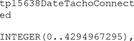 |
| RTM18 Current Speed | The VU shall generate an integer value for data element RTM18. The VU shall set the value for RTM16 to the last current recorded speed at the time of the latest update of the RtmData. | Last current recorded speed |  |
| RTM19 Timestamp | For data element RTM19 the VU shall generate an integer value (timeReal from Appendix 1). The VU shall set the value for RTM19 to the time of the latest update of the RtmData. | Timestamp of current TachographPayload record |  |
5.4.6 Data transfer mechanism U.K.
DSC_42Payload data defined previously are requested by the REDCR after initialisation phase, and consequently transmitted by the DSRC-VU in the allocated window. The command GET is used by the REDCR to retrieve data.U.K.
[F1DSC_43 For all DSRC exchanges, data shall be encoded using PER (Packed Encoding Rules) UNALIGNED, apart from  and
and  , which shall be encoded using OER (Octet Encoding Rules) defined in ISO/IEC 8825-7, Rec. ITU-T X.696.] U.K.
5.4.7 Detailed DSRC transaction description U.K.
DSC_44Initialisation is performed according to DSC_44 — DSC_48 and Tables 14.4 — 14.9. In the initialisation phase, the REDCR starts sending a frame containing a BST (Beacon Service Table) according to EN 12834 and EN 13372, 6.2, 6.3, 6.4 and 7.1 with settings as specified in the following Table 14.4.U.K.
| Table 14.4 | |
| Initialisation — BST frame settings | |
| Field | Settings |
|---|---|
| Link Identifier | Broadcast address |
| BeaconId | As per EN 12834 |
| Time | As per EN 12834 |
| Profile | No extension, 0 or 1 to be used |
| MandApplications | No extension, EID not present, Parameter not present, AID= 2 Freight&Fleet |
| NonMandApplications | Not present |
| ProfileList | No extension, number of profiles in list = 0 |
| Fragmentation header | No fragmentation |
| Layer 2 settings | Command PDU, UI command |
A practical example of the settings specified in Table 14.4, with an indication of bit encodings, is given in the following Table 14.5.
| Table 14.5 | |||
| Initialisation — BST frame contents example | |||
| Octet # | Attribute/Field | Bits in octet | Description |
|---|---|---|---|
| 1 | FLAG |  | Start flag |
| 2 | Broadcast ID |  | Broadcast address |
| 3 | MAC Control Field |  | Command PDU |
| 4 | LLC Control field |  | UI command |
| 5 | Fragmentation header |  | No fragmentation |
| 6 | BST |  | Initialisation request |
| SEQUENCE { | |||
| OPTION indicator BeaconID SEQUENCE { ManufacturerId INTEGER (0..65535) |  | NonMand applications not present | |
 | Manufacturer Identifier | ||
| 7 |  | ||
| 8 |  | ||
| IndividualID INTEGER (0..134217727) } |  | 27 bit ID available for manufacturer | |
| 9 |  | ||
| 10 |  | ||
| 11 |  | ||
| 12 | Time INTEGER (0..4294967295) |  | 32 bit UNIX real time |
| 13 |  | ||
| 14 |  | ||
| 15 |  | ||
| 16 | Profile INTEGER (0..127,...) |  | No extension. Example profile 0 |
| 17 | MandApplications SEQUENCE (SIZE(0..127,...)) OF { |  | No extension, Number of mandApplications = 1 |
| 18 | SEQUENCE { | ||
| OPTION indicator |  | EID not present | |
| OPTION indicator |  | Parameter not present | |
| AID DSRCApplicationEntityID } } |  | No extension. AID= 2 Freight&Fleet | |
| 19 | ProfileList SEQUENCE (0..127,...) OF Profile } |  | No extension, number of profiles in list = 0 |
| 20 | FCS |  | Frame check sequence |
| 21 |  | ||
| 22 | Flag |  | End Flag |
DSC_45A DSRC-VU, when receiving a BST, requires the allocation of a private window, as specified by EN 12795 and EN 13372, 7.1.1, with no specific RTM settings. Table 14.6 provides an example of bit encoding.U.K.
| Table 14.6 | |||
| Initialisation — Private window allocation request frame contents | |||
| Octet # | Attribute/Field | Bits in octet | Description |
|---|---|---|---|
| 1 | FLAG |  | Start flag |
| 2 | Private LID |  | Link address of specific DSRC-VU |
| 3 |  | ||
| 4 |  | ||
| 5 |  | ||
| 6 | MAC Control field |  | Private window request |
| 7 | FCS |  | Frame check sequence |
| 8 |  | ||
| 9 | Flag |  | End Flag |
DSC_46The REDCR then answers by allocating a private window, as specified by EN 12795 and EN 13372, 7.1.1 with no specific RTM settings.U.K.
Table 14.7 provides an example of bit encoding.
| Table 14.7 | |||
| Initialisation — Private window allocation frame contents | |||
| Octet # | Attribute/Field | Bits in octet | Description |
|---|---|---|---|
| 1 | FLAG |  | Start flag |
| 2 | Private LID |  | Link address of the specific DSRC-VU |
| 3 |  | ||
| 4 |  | ||
| 5 |  | ||
| 6 | MAC Control field |  | Private window allocation |
| 7 | FCS |  | Frame check sequence |
| 8 |  | ||
| 9 | Flag |  | End Flag |
DSC_47The DSRC-VU, when receiving the private window allocation, sends its VST (Vehicle Service Table) as defined in EN 12834 and EN 13372, 6.2, 6.3, 6.4 and 7.1 with settings as specified Table 14.8, using the allocated transmission window.U.K.
| Table 14.8 | |
| Initialisation — VST frame settings | |
| Field | Settings |
|---|---|
| Private LID | As per EN 12834 |
| VST parameters | Fill=0, then for each supported application: EID present, parameter present, AID=2, EID as generated by the OBU |
| Parameter | No extension, Contains the RTM Context Mark |
| ObeConfiguration | The optional ObeStatus field may be present, but shall not be used by the REDCR |
| Fragmentation header | No fragmentation |
| Layer 2 settings | Command PDU, UI command |
DSC_48The DSRC-VU shall support the ‘Freight and Fleet’ application, identified by the Application Identifier ‘2’. Other Application Identifiers may be supported, but shall not be present in this VST, as the BST only requires AID=2. The ‘Applications’ field contains a list of the supported application instances in the DSRC-VU. For each supported application instantiation, a reference to the appropriate standard is given, made of an Rtm Context mark, which is composed of an OBJECT IDENTIFIER representing the related standard, its part (9 for RTM) and possibly its version, plus an EID that is generated by the DSRC-VU, and associated to that application instance.U.K.
A practical example of the settings specified in Table 14.8, with an indication of bit encodings, is given in Table 14.9.
| Table 14.9 | |||
| Initialisation — VST frame contents example | |||
| Octet # | Attribute/Field | Bits in octet | Description |
|---|---|---|---|
| 1 | FLAG |  | Start flag |
| 2 | Private LID |  | Link address of the specific DSRC-VU |
| 3 |  | ||
| 4 |  | ||
| 5 |  | ||
| 6 | MAC Control field |  | Command PDU |
| 7 | LLC Control field |  | UI command |
| 8 | Fragmentation header |  | No fragmentation |
| 9 | VST SEQUENCE { |  | Initialisation response |
| Fill BIT STRING (SIZE(4)) |  | Unused and set to 0 | |
| 10 | Profile INTEGER (0..127,...) Applications SEQUENCE OF { |  | No extension. Example profile 0 |
| 11 |  | No extension, 1 application | |
| 12 | SEQUENCE { | ||
| OPTION indicator |  | EID present | |
| OPTION indicator |  | Parameter present | |
| AID DSRCApplicationEntityID |  | No extension. AID= 2 Freight&Fleet | |
| 13 | EID Dsrc-EID |  | Defined within the OBU and identifying the application instance. |
| 14 | Parameter Container { |  | No extension, Container Choice = 02, Octet string |
| 15 |  | No extension, Rtm Context Mark length = 8 | |
| 16 | Rtm-ContextMark::= SEQUENCE { StandardIdentifier standardIdentifier |  | [F1Object Identifier of the supported standard, part, and version. Example: ISO (1) Standard (0) TARV (15638) part9 (9) Version1 (1). First octet is 06H, which is the Object Identifier. Second octet is 06H, which is its length. Subsequent 6 octets encode the example Object Identifier.] |
| 17 |  | ||
| 18 |  | ||
| 19 |  | ||
| 20 |  | ||
| 21 |  | ||
| 22 |  | ||
| 23 |  | ||
| 24 | ObeConfiguration Sequence { | ||
| OPTION indicator |  | ObeStatus not present | |
| EquipmentClass INTEGER (0..32767) |  | ||
| 25 |  | ||
| 26 | ManufacturerId INTEGER (0..65535) |  | Manufacturer identifier for the DSRC-VU as described in ISO 14816 Register |
| 27 |  | ||
| 28 | FCS |  | Frame check sequence |
| 29 |  | ||
| 30 | Flag |  | End Flag |
DCS_49The REDCR then reads the data by issuing a GET command, conforming to the GET command defined in EN 13372, 6.2, 6.3, 6.4 and EN 12834, with settings as specified in Table 14.10.U.K.
| Table 14.10 | |
| Presentation — GET request frame settings | |
| Field | Settings |
|---|---|
| Invoker Identifier (IID) | Not present |
| Link Identifier (LID) | Link address of the specific DSRC-VU |
| Chaining | No |
| Element Identifier (EID) | As specified in the VST. No extension |
| Access Credentials | No |
| AttributeIdList | No extension, 1 attribute, AttributeID = 1 (RtmData) |
| Fragmentation | No |
| Layer2 settings | Command PDU, Polled ACn command |
Table 14.11 shows an example of reading the RTM data.
| Table 14.11 | |||
| Presentation — Get Request frame example | |||
| Octet # | Attribute/Field | Bits in octet | Description |
|---|---|---|---|
| 1 | FLAG |  | Start flag |
| 2 | Private LID |  | Link address of the specific DSRC-VU |
| 3 |  | ||
| 4 |  | ||
| 5 |  | ||
| 6 | MAC Control field |  | Command PDU |
| 7 | LLC Control field |  | Polled ACn command, n bit |
| 8 | Fragmentation header |  | No fragmentation |
| 9 | Get.request SEQUENCE { |  | Get request |
| OPTION indicator |  | Access Credentials not present | |
| OPTION indicator |  | IID not present | |
| OPTION indicator |  | AttributeIdList present | |
| Fill BIT STRING(SIZE(1)) |  | Set to 0. | |
| 10 | EID INTEGER(0..127,…) |  | The EID of the RTM application instance, as specified in the VST. No extension |
| 11 | AttributeIdList SEQUENCE OF { AttributeId }} |  | No extension, number of attributes = 1 |
| 12 |  | AttributeId=1, RtmData. No extension | |
| 13 | FCS |  | Frame check sequence |
| 14 |  | ||
| 15 | Flag |  | End Flag |
DSC_50The DSRC-VU, when receiving the GET request, sends a GET response with the requested data conforming to the GET response defined in EN 13372, 6.2, 6.3, 6.4 and EN 12834, with settings as specified in Table 14.12.U.K.
| Table 14.12 | |
| Presentation — GET response frame settings | |
| Field | Settings |
|---|---|
| Invoker Identifier (IID) | Not present |
| Link Identifier (LID) | As per EN 12834 |
| Chaining | No |
| Element Identifier (EID) | As specified in the VST. |
| Access Credentials | No |
| Fragmentation | No |
| Layer2 settings | Response PDU, Response available and command accepted, ACn command |
Table 14.13 shows an example of reading the RTM data.
| Table 14.13 | |||
| Presentation — Response frame contents example | |||
| Octet # | Attribute/Field | Bits in octet | Description |
|---|---|---|---|
| 1 | FLAG |  | Start flag |
| 2 | Private LID |  | Link address of the specific DSRC-VU |
| 3 |  | ||
| 4 |  | ||
| 5 |  | ||
| 6 | MAC Control field |  | Response PDU |
| 7 | LLC Control field |  | Response available, ACn command n bit |
| 8 | LLC Status field |  | Response available and command accepted |
| 9 | Fragmentation header |  | No fragmentation |
| 10 | Get.response SEQUENCE { |  | Get response |
| OPTION indicator |  | IID not present | |
| OPTION indicator |  | Attribute List present | |
| OPTION indicator |  | Return status not present | |
| Fill BIT STRING(SIZE(1)) |  | Not used | |
| 11 | EID INTEGER(0..127,…) |  | Responding from the RTM application Instance. No extension, |
| 12 | AttributeList SEQUENCE OF { |  | No extension, number of attributes = 1 |
| 13 | Attributes SEQUENCE { AttributeId |  | No extension, AttributeId=1 (RtmData) |
| 14 | AttributeValue CONTAINER { |  | No extension, Container Choice = 1010. |
| 15 |  | RtmData | |
| 16 |  | ||
| 17 |  | ||
| … | … | ||
| n | }}}} |  | |
| n+1 | FCS |  | Frame check sequence |
| n+2 |  | ||
| n+3 | Flag |  | End Flag |
DSC_51The REDCR then closes the connection by issuing a EVENT_REPORT, RELEASE command conforming to EN 13372, 6.2, 6.3, 6.4 and EN 12834,7.3.8, with no specific RTM settings. Table 14.14 shows a bit encoding example of the RELEASE command.U.K.
| Table 14.14 | |||
| Termination. EVENT_REPORT Release frame contents | |||
| Octet # | Attribute/Field | Bits in octet | Description |
|---|---|---|---|
| 1 | FLAG |  | Start flag |
| 2 | Private LID |  | Link address of the specific DSRC-VU |
| 3 |  | ||
| 4 |  | ||
| 5 |  | ||
| 6 | MAC Control field |  | The frame contains a command LPDU |
| 7 | LLC Control field |  | UI command |
| 8 | Fragmentation header |  | No fragmentation |
| 9 | EVENT_REPORT.request SEQUENCE { |  | EVENT_REPORT (Release) |
| OPTION indicator |  | Access Credentials not present | |
| OPTION indicator |  | Event parameter not present | |
| OPTION indicator |  | IID not present | |
| Mode BOOLEAN |  | No response expected | |
| 10 | EID INTEGER (0..127,…) |  | No extension, EID = 0 (System) |
| 11 | EventType INTEGER (0..127,…) } |  | Event type 0 = Release |
| 12 | FCS |  | Frame check sequence |
| 13 |  | ||
| 14 | Flag |  | End Flag |
DSC_52The DSRC-VU is not expected to answer to the Release command. The communication is then closed.U.K.
5.4.8 DSRC Test transaction description U.K.
DSC_53Full tests that include securing the data, need to be carried out as defined in Appendix 11 Common Security Mechanisms, by authorised persons with access to security procedures, using the normal GET command as defined above.U.K.
DSC_54Commissioning and periodic inspection tests that require decrypting and comprehension of the decrypted data content shall be undertaken as specified in Appendix 11 Common Security Mechanisms and Appendix 9, Type Approval List of Minimum required tests.U.K.
However, the basic DSRC communication can be tested by the command ECHO. Such tests may be required on commissioning, at periodic inspection, or otherwise to the requirement of the competent control authority or Regulation (EU) No 165/2014 (See 6 below)
DSC_55In order to effect this basic communication test, the ECHO command is issued by the REDCR during a session, i.e., after an initialisation phase has been completed successfully. The sequence of interactions is thus similar to that of an interrogation:U.K.
— Step 1
The REDCR sends a ‘beacon service table’ (BST) that includes the application identifiers (AIDs) in the service list that it supports. In the RTM applications this will simply be the service with the AID value = 2.
The DSRC-VU evaluates the received BST, and where it identifies that the BST is requesting Freight&Fleet (AID = 2), the DSRC-VU shall respond. If the REDCR does not offer AID=2, the DSRC-VU shall shut down its transaction with the REDCR.
— Step 2
The DSRC-VU sends a request for a private window allocation.
— Step 3
The REDCR sends a private window allocation.
— Step 4
The DSRC-VU uses the allocated private window to send its vehicle service table (VST). This VST includes a list of all the different application instantiations that this DSRC-VU supports in the framework of AID=2. The different instantiations shall be identified by means of uniquely EIDs, each associated with a parameter value indicating the instance of the application that is supported.
— Step 5
Next the REDCR analyses the offered VST, and either terminates the connection (RELEASE) since it is not interested in anything the VST has to offer (i.e., it is receiving a VST from a DSRC-VU that is not an RTM VU, or, if it receives an appropriate VST it starts an app instantiation.
— Step 6
The REDCR shall issue a command (ECHO) to the specific DSRC-VU, and allocates a private window.
— Step 7
The DSRC-VU uses the newly allocated private window to send an ECHO response frame.
The following tables give a practical example of an ECHO exchange session.
DSC_56Initialisation is performed according to 5.4.7 (DSC_44 — DSC_48) and Tables 14.4 — 14.9U.K.
DSC_57The REDCR then issues an ACTION, ECHO command conforming to ISO 14906, containing 100 octets of data and with no specific settings for RTM. Table 14.15 shows the contents of the frame sent by the REDCR.U.K.
| Table 14.15 | |||
| ACTION, ECHO request frame example | |||
| Octet # | Attribute/Field | Bits in octet | Description |
|---|---|---|---|
| 1 | FLAG |  | Start flag |
| 2 | Private LID |  | Link address of the specific DSRC-VU |
| 3 |  | ||
| 4 |  | ||
| 5 |  | ||
| 6 | MAC Control field |  | Command PDU |
| 7 | LLC Control field |  | Polled ACn command, n bit |
| 8 | Fragmentation header |  | No fragmentation |
| 9 | ACTION.request SEQUENCE { |  | Action request (ECHO) |
| OPTION indicator |  | Access Credentials not present | |
| OPTION indicator |  | Action parameter present | |
| OPTION indicator |  | IID not present | |
| Mode BOOLEAN |  | Response expected | |
| 10 | EID INTEGER (0..127,…) |  | No extension, EID = 0 (System) |
| 11 | ActionType INTEGER (0..127,…) |  | No extension, Action type ECHO request |
| 12 | ActionParameter CONTAINER { |  | No extension, Container Choice = 2 |
| 13 |  | No extension. String length = 100 octets | |
| 14 |  | Data to be echoed | |
| … | … | ||
| 113 | }} |  | |
| 114 | FCS |  | Frame check sequence |
| 115 |  | ||
| 116 | Flag |  | End Flag |
DSC_58The DSRC-VU, when receiving the ECHO request, sends an ECHO response of 100 octets of data by reflecting the received command, according to ISO 14906, with no specific settings for RTM. Table 14.16 shows a bit level encoding example.U.K.
| Table 14.16 | |||
| ACTION, ECHO response frame example | |||
| Octet # | Attribute/Field | Bits in octet | Description |
|---|---|---|---|
| 1 | FLAG |  | Start flag |
| 2 | Private LID |  | Link address of the specific VU |
| 3 |  | ||
| 4 |  | ||
| 5 |  | ||
| 6 | MAC Control field |  | Response PDU |
| 7 | LLC Control field |  | ACn command n bit |
| 8 | LLC status field |  | Response available |
| 9 | Fragmentation header |  | No fragmentation |
| 10 | ACTION.response SEQUENCE { |  | ACTION response (ECHO) |
| OPTION indicator |  | IID not present | |
| OPTION indicator |  | Response parameter present | |
| OPTION indicator |  | Return status not present | |
| Fill BIT STRING (SIZE (1)) |  | Not used | |
| 11 | EID INTEGER (0..127,…) |  | No extension, EID = 0 (System) |
| 12 | ResponseParameter CONTAINER { |  | No extension, Container Choice = 2 |
| 13 |  | No extension. String length = 100 octets | |
| 14 |  | Echoed data | |
| … | … | ||
| 113 | }} |  | |
| 114 | FCS |  | Frame check sequence |
| 115 |  | ||
| 116 | Flag |  | End Flag |
Options/Help
Print Options
PrintThe Whole Regulation
PrintThe Whole Annex
PrintThe Whole Division
PrintThe Whole Division
PrintThis Division only
You have chosen to open the Whole Regulation
The Whole Regulation you have selected contains over 200 provisions and might take some time to download. You may also experience some issues with your browser, such as an alert box that a script is taking a long time to run.
Would you like to continue?
You have chosen to open Schedules only
The Schedules you have selected contains over 200 provisions and might take some time to download. You may also experience some issues with your browser, such as an alert box that a script is taking a long time to run.
Would you like to continue?
Legislation is available in different versions:
Latest Available (revised):The latest available updated version of the legislation incorporating changes made by subsequent legislation and applied by our editorial team. Changes we have not yet applied to the text, can be found in the ‘Changes to Legislation’ area.
Original (As adopted by EU): The original version of the legislation as it stood when it was first adopted in the EU. No changes have been applied to the text.
See additional information alongside the content
Geographical Extent: Indicates the geographical area that this provision applies to. For further information see ‘Frequently Asked Questions’.
Show Timeline of Changes: See how this legislation has or could change over time. Turning this feature on will show extra navigation options to go to these specific points in time. Return to the latest available version by using the controls above in the What Version box.
Opening Options
Different options to open legislation in order to view more content on screen at once
More Resources
Access essential accompanying documents and information for this legislation item from this tab. Dependent on the legislation item being viewed this may include:
- the original print PDF of the as adopted version that was used for the EU Official Journal
- lists of changes made by and/or affecting this legislation item
- all formats of all associated documents
- correction slips
- links to related legislation and further information resources
Timeline of Changes
This timeline shows the different versions taken from EUR-Lex before exit day and during the implementation period as well as any subsequent versions created after the implementation period as a result of changes made by UK legislation.
The dates for the EU versions are taken from the document dates on EUR-Lex and may not always coincide with when the changes came into force for the document.
For any versions created after the implementation period as a result of changes made by UK legislation the date will coincide with the earliest date on which the change (e.g an insertion, a repeal or a substitution) that was applied came into force. For further information see our guide to revised legislation on Understanding Legislation.
More Resources
Use this menu to access essential accompanying documents and information for this legislation item. Dependent on the legislation item being viewed this may include:
- the original print PDF of the as adopted version that was used for the print copy
- correction slips
Click 'View More' or select 'More Resources' tab for additional information including:
- lists of changes made by and/or affecting this legislation item
- confers power and blanket amendment details
- all formats of all associated documents
- links to related legislation and further information resources
 All content is available under the Open Government Licence v3.0 except where otherwise stated. This site additionally contains content derived from EUR-Lex, reused under the terms of the Commission Decision 2011/833/EU on the reuse of documents from the EU institutions. For more information see the EUR-Lex public statement on re-use.