- Latest available (Revised)
- Original (As adopted by EU)
Commission Directive 2005/12/ECShow full title
Commission Directive 2005/12/EC of 18 February 2005 amending Annexes I and II to Directive 2003/25/EC of the European Parliament and of the Council on specific stability requirements for ro-ro passenger ships (Text with EEA relevance)
You are here:

What Version
Advanced Features
- Show Geographical Extent(e.g. England, Wales, Scotland and Northern Ireland)
- Show Timeline of Changes
More Resources
This is a Directive originating from the EU


This is a legislation item that originated from the EU
After exit day there will be three versions of this legislation to consult for different purposes. The legislation.gov.uk version is the version that applies in the UK. The EU Version currently on EUR-lex is the version that currently applies in the EU i.e you may need this if you operate a business in the EU.
The web archive version is the official version of this legislation item as it stood on exit day before being published to legislation.gov.uk and any subsequent UK changes and effects applied. The web archive also captured associated case law and other language formats from EUR-Lex.
Changes over time for:
Status:
EU Directives are being published on this site to aid cross referencing from UK legislation. After IP completion day (31 December 2020 11pm) no further amendments will be applied to this version.
“AppendixModel test method
1.ObjectivesU.K.
This revised model test method is a revision of the method contained in the Appendix to the Annex to resolution 14 of the 1995 SOLAS Conference. Since the entry into force of the Stockholm Agreement a number of model tests has been carried out in accordance with the test method previously in force. During these tests a number of refinements in the procedures have been identified. This new model test method aims to include these refinements and, together with the appended Guidance Notes, provide a more robust procedure for the assessment of survivability of a damaged ro-ro passenger ship in a seaway. In the tests provided for in paragraph 1.4 of the stability requirements included in Annex I, the ship should be capable of withstanding a seaway as defined in paragraph 4 hereunder in the worst-damage-case scenario.
2.DefinitionsU.K.
| LBP | is the length between perpendiculars |
| HS | is the significant wave height |
| B | is the moulded breadth of the ship |
| TP | is the peak period |
| TZ | is the zero crossing period |
3.Ship modelU.K.
3.1.The model should copy the actual ship for both outer configuration and internal arrangement, in particular all damaged spaces having an effect on the process of flooding and shipping of water. Intact draught, trim, heel and limiting operational KG corresponding to the worst damage case should be used. Furthermore, the test case(s) to be considered should represent the worst damage case(s) defined in accordance with SOLAS regulation II-1/8.2.3.2 (SOLAS 90) with regard to the total area under the positive GZ curve and the centreline of the damage opening should be located within the following range:U.K.
3.1.1.± 35 % LBP from midship;U.K.
3.1.2.an additional test will be required for the worst damage within ± 10 % LBP from midship if the damage case referred to in .1 is outside of ± 10 % LBP from midship.U.K.
3.2.The model should comply with the following:U.K.
3.2.1.length between perpendiculars (LBP) is to be at least 3 m or a length corresponding to a model scale of 1:40, whichever is greater, and the vertical extent up to at least three superstructure standard heights above the bulkhead (freeboard) deck;U.K.
3.2.2.hull thickness of flooded spaces should not exceed 4 mm;U.K.
3.2.3.in both intact and damaged conditions, the model should satisfy the correct displacement and draught marks (TA, TM, TF, port and starboard) with a maximum tolerance in any one draught mark of + 2 mm. Draught marks forward and aft should be located as near FP and AP as practicable;U.K.
3.2.4.all damaged compartments and ro-ro spaces should be modelled with the correct surface and volume permeabilities (actual values and distributions) ensuring that floodwater mass and mass distribution are correctly represented;U.K.
3.2.5.the characteristics of motion of the actual ship should be modelled properly, paying particular attention to the intact GM tolerance and radii of gyration in roll and pitch motion. Both radii should be measured in air and be in the range of 0,35B to 0,4B for roll motion, and 0,2LOA to 0,25LOA for pitch motion;U.K.
3.2.6.main design features such as watertight bulkheads, air escapes, etc., above and below the bulkhead deck that can result in asymmetric flooding should be modelled properly as far as practicable to represent the real situation; Ventilating and cross-flooding arrangements should be constructed to a minimum cross section of 500 mm2;U.K.
3.2.7.the shape of the damage opening should be as follows:U.K.
1.
trapezoidal profile with side at 15° slope to the vertical and the width at the design waterline defined according to SOLAS regulation II-1/8.4.1;
2.
isosceles triangular profile in the horizontal plane with the height equal to B/5 according to SOLAS regulation II-1/8.4.2. If side casings are fitted within B/5, the damaged length in way of the side casings should not be less than 25 mm;
3.
notwithstanding the provisions of subparagraphs 3.2.7.1 and 3.2.7.2 above, all compartments taken as damaged in calculating the worst damage case(s) referred to in paragraph 3.1 should be flooded in the model tests;
3.3.The model in the flooded equilibrium condition should be heeled by an additional angle corresponding to that induced by the heeling moment Mh = max (Mpass; Mlaunch)-Mwind, but in no case should the final heel be less than 1° towards damage. Mpass, Mlaunch and Mwind are as specified in SOLAS regulation II-1/8.2.3.4. For existing ships this angle may be taken as 1°.U.K.
4.Procedure for experimentsU.K.
4.1.The model should be tested in a long-crested irregular seaway defined by the JONSWAP spectrum with significant wave height HS, a peak enhancement factor γ = 3,3 and a peak period 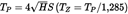 . HS is the significant wave height for the area of operation, which is not exceeded by a probability of more than 10 % on a yearly basis, but limited to a maximum of 4 m.U.K.
Furthermore,
4.1.1.the basin width should be sufficient to avoid contact or other interaction with the sides of the basin and is recommended not to be less than LBP + 2 m;U.K.
4.1.2.the basin depth should be sufficient for proper wave modelling but should not be less than 1 m;U.K.
4.1.3.for a representative wave realisation to be used, measurements should be performed prior to the test at three different locations within the drift range;U.K.
4.1.4.the wave probe closer to the wave maker should be located at the position where the model is placed when the test starts;U.K.
4.1.5.variation in HS and TP should be within ± 5 % for the three locations; andU.K.
4.1.6.during the tests, for approval purposes, a tolerance of + 2,5 % in HS, ± 2,5 % in TP and ± 5 % in TZ should be allowed with reference to the probe closer to the wave maker.U.K.
4.2.The model should be free to drift and placed in beam seas (90° heading) with the damage hole facing the oncoming waves, with no mooring system permanently attached to the model used. To maintain a beam sea heading of approximately 90° during the model test the following requirements should be satisfied:U.K.
4.2.1.heading control lines, intended for minor adjustment, should be located at the centre line of the stem and stern, in a symmetrical fashion and at a level between the position of KG and the damaged waterline; andU.K.
4.2.2.the carriage speed should be equal to the actual drift speed of the model with speed adjustment made when necessary.U.K.
4.3.At least 10 experiments should be carried out. The test period for each experiment should be of a duration such that a stationary state is reached, but not less than 30 min in full-scale. A different wave realisation train should be used for each experiment.U.K.
5.Survival criteriaU.K.
The model should be considered as surviving if a stationary state is reached for the successive test runs as required in paragraph 4.3. The model should be considered as capsized if angles of roll of more than 30° to the vertical axis or steady (average) heel greater than 20° for a period longer than three minutes full-scale occur, even if a stationary state is reached.
6.Test documentationU.K.
6.1.The model test programme should be approved by the Administration in advance.U.K.
6.2.Tests should be documented by means of a report and a video or other visual records containing all relevant information on the model and the test results, which are to be approved by the Administration. These should include, as a minimum, the theoretical and measured wave spectra and statistics (HS, TP, TZ) of the wave elevation at the three different locations in the basin for a representative realisation, and for the tests with the model, the time series of main statistics of the measured wave elevation close to the wave maker and records of model roll, heave and pitch motions, and of the drift speed.”U.K.
Options/Help
Print Options
PrintThe Whole Directive
PrintThe Whole Annex
Legislation is available in different versions:
Latest Available (revised):The latest available updated version of the legislation incorporating changes made by subsequent legislation and applied by our editorial team. Changes we have not yet applied to the text, can be found in the ‘Changes to Legislation’ area.
Original (As adopted by EU): The original version of the legislation as it stood when it was first adopted in the EU. No changes have been applied to the text.
See additional information alongside the content
Geographical Extent: Indicates the geographical area that this provision applies to. For further information see ‘Frequently Asked Questions’.
Show Timeline of Changes: See how this legislation has or could change over time. Turning this feature on will show extra navigation options to go to these specific points in time. Return to the latest available version by using the controls above in the What Version box.
Opening Options
Different options to open legislation in order to view more content on screen at once
More Resources
Access essential accompanying documents and information for this legislation item from this tab. Dependent on the legislation item being viewed this may include:
- the original print PDF of the as adopted version that was used for the EU Official Journal
- lists of changes made by and/or affecting this legislation item
- all formats of all associated documents
- correction slips
- links to related legislation and further information resources
Timeline of Changes
This timeline shows the different versions taken from EUR-Lex before exit day and during the implementation period as well as any subsequent versions created after the implementation period as a result of changes made by UK legislation.
The dates for the EU versions are taken from the document dates on EUR-Lex and may not always coincide with when the changes came into force for the document.
For any versions created after the implementation period as a result of changes made by UK legislation the date will coincide with the earliest date on which the change (e.g an insertion, a repeal or a substitution) that was applied came into force. For further information see our guide to revised legislation on Understanding Legislation.
More Resources
Use this menu to access essential accompanying documents and information for this legislation item. Dependent on the legislation item being viewed this may include:
- the original print PDF of the as adopted version that was used for the print copy
- correction slips
Click 'View More' or select 'More Resources' tab for additional information including:
- lists of changes made by and/or affecting this legislation item
- confers power and blanket amendment details
- all formats of all associated documents
- links to related legislation and further information resources
 All content is available under the Open Government Licence v3.0 except where otherwise stated. This site additionally contains content derived from EUR-Lex, reused under the terms of the Commission Decision 2011/833/EU on the reuse of documents from the EU institutions. For more information see the EUR-Lex public statement on re-use.