- Latest available (Revised)
- Original (As adopted by EU)
Directive 2000/14/EC of the European Parliament and of the CouncilShow full title
Directive 2000/14/EC of the European Parliament and of the Council of 8 May 2000 on the approximation of the laws of the Member States relating to the noise emission in the environment by equipment for use outdoors
You are here:

What Version
Advanced Features
- Show Geographical Extent(e.g. England, Wales, Scotland and Northern Ireland)
- Show Timeline of Changes
More Resources
Revised version PDFs
- Revised 26/07/20191.34 MB
- Revised 20/04/20090.74 MB
- Revised 27/12/20052.75 MB
This is a Directive originating from the EU


This is a legislation item that originated from the EU
After exit day there will be three versions of this legislation to consult for different purposes. The legislation.gov.uk version is the version that applies in the UK. The EU Version currently on EUR-lex is the version that currently applies in the EU i.e you may need this if you operate a business in the EU.
The web archive version is the official version of this legislation item as it stood on exit day before being published to legislation.gov.uk and any subsequent UK changes and effects applied. The web archive also captured associated case law and other language formats from EUR-Lex.
Changes over time for: ANNEX III
Status:
EU Directives are being published on this site to aid cross referencing from UK legislation. After IP completion day (31 December 2020 11pm) no further amendments will be applied to this version.
ANNEX IIIU.K.METHOD OF MEASUREMENT OF AIRBORNE NOISE EMITTED BY EQUIPMENT FOR USE OUTDOORS
ScopeU.K.
This Annex lays down the methods of measurement of airborne noise that shall be used for the determination of the sound power levels of equipment covered by this Directive with a view to the conformity assessment procedures of this Directive.
Part A of this Annex for each type of equipment referred to in Article 2(1) lays down
basic noise emission standards
general supplements to these basic noise emission standards
for measuring the sound pressure level on a measurement surface enveloping the source and for calculating the sound power level produced by the source.
Part B of this Annex for each type of equipment referred to in Article 2(1) lays down
a recommended basic noise emission standard including
a reference to the basic noise emission standard chosen from Part A
the test area
the value of the constant K2A
the shape of the measurement surface
the number and position of microphones to be used
operating conditions including
the reference to a standard, if any
requirements relating to mounting of the equipment
a method to calculate the resulting sound power levels in the event that several tests with different operating conditions are to be used
further information.
When testing specific types of equipment, the manufacturer or his authorised representative in the Community may in general choose one of the basic noise emission standards of Part A and apply the operating conditions of Part B for this specific type of equipment. In the event of a dispute, however, the recommended basic noise emission standard laid down in Part B has to be used together with the operating conditions of Part B.
PART ABASIC NOISE EMISSION STANDARD
For the determination of the sound power level of equipment for use outdoors as defined by Article 2(1) the basic noise emission standards
EN ISO 3744:1995
EN ISO 3746:1995
may generally be used subject to the following general supplements:
1.Measurement uncertaintyU.K.
Measurement uncertainties are not taken into account in the framework of conformity assessment procedures in the design phase.
2.Operation of source during testU.K.
2.1.Fan speedU.K.
If the engine of the equipment or its hydraulic system is fitted with (a) fans(s) it (they) must operate during the test. The fan speed is, in accordance with one of the following conditions, stated and set by the manufacturer of the equipment and must appear in the test report, this speed being used in further measurements.
(a)
Fan drive directly connected to the engine
If the fan drive is directly connected to the engine and/or hydraulic equipment (e.g. by belt drive) it must operate during the test.
(b)
Fan drive with several distinct speeds
If the fan can work at several distinct speeds the test shall be carried out either
at its maximum working speed, or
in a first test with the fan set at zero speed and in a second test the fan set at maximum speed. The resulting sound pressure level L pA shall then be calculated by combining both test results using the following equation:
where:
L pA,0 % is the sound pressure level determined with the fan set at zero speed
L pA,100 % is the sound pressure level determined with the fan set at maximum speed.

(c)
Fan drive with continuous variable speed
If the fan can work at continuous variable speed, the test shall be carried out either according to 2.1(b) or with the fan speed set by the manufacturer at no less than 70 % of the maximum speed.
2.2.Test of powered equipment free of loadU.K.
For these measurements, the engine and hydraulic system of the equipment must be warmed up in accordance with the instructions, and safety requirements must be observed.
The test is carried out with the equipment in a stationary position without operating the working equipment or travelling mechanism. For the purpose of the test, the engine will idle at no less than the rated speed corresponding to the net power(1).
If the machine is powered by a generator or from the mains, the frequency of the supply current, specified for the motor by the manufacturer, shall be stable at ± 1 Hz if the machine is equipped with an induction motor, and the supply voltage at ± 1 % of the rated voltage if the machine is equipped with a commutator motor. The supply voltage is measured at the plug of a non-detachable cable or cord, or at the inlet of the machine if a detachable cable is provided. The waveform of the current supplied from the generator shall be similar to that obtained from the mains.
If the machine is powered by battery, the battery shall be fully charged.
The speed used and the corresponding net power are stated by the manufacturer of the equipment and must appear in the test report.
If the equipment is fitted with several engines, they must work simultaneously during the tests. If this is not possible, each possible combination of engine(s) is to be tested.
2.3.Test of powered equipment under loadU.K.
For these measurements, the engine (driving device) and hydraulic system of the equipment must be warmed up in accordance with the instructions, and safety requirements must be observed. No signalling device such as a warning horn or reversing alarm is to be operated during the test.
The speed or velocity of the equipment during the test must be recorded and appear in the test report.
If the equipment is fitted with several engines and/or aggregates they must work simultaneously during the tests. If this is not possible, each possible combination of engine(s) and/or aggregates is to be tested.
For each type of equipment that is to be tested under load, specific operating conditions must be laid down which shall, in principle, produce effects and stresses similar to those encountered under actual working conditions.
2.4.Test of hand-operated equipmentU.K.
Conventional operating conditions for each type of hand-operated equipment shall be laid down that produce effects and stresses similar to those undergone under actual working conditions.
3.Calculation of surface sound pressure levelU.K.
The surface sound pressure level shall be determined at least three times. If at least two of the determined values do not differ by more than 1 dB, further measurements will not be necessary; otherwise the measurements shall be continued until two values differing by no more than 1 dB are obtained. The A-weighted surface sound pressure level to be used for calculating the sound power level is the arithmetic mean of the two highest values that do not differ by more than 1 dB.
4.Information to be reportedU.K.
The A-weighted sound power level of the source under test shall be reported to the nearest whole number (less than 0,5 use the lower number; greater than or equal to 0,5 use the higher number).
The report shall contain the technical data necessary to identify the source under test as well as the noise test code and the acoustical data.
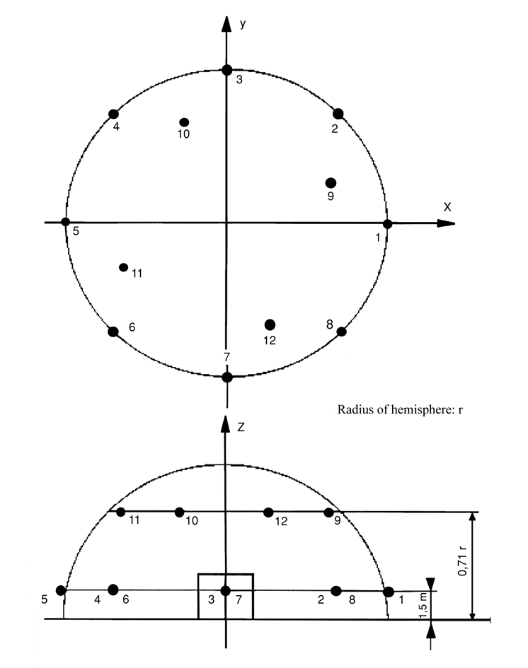
5.Additional microphone positions on the hemispherical measurement surface (EN ISO 3744:1995) U.K.
In addition to clauses 7.2.1 and 7.2.2 of EN ISO 3744:1995 a set of 12 microphones on the hemispherical measurement surface may be used. The location of 12 microphone positions distributed on the surface of a hemisphere of radius r are listed in the form of Cartesian coordinates in the following table. The radius r of the hemisphere shall be equal to or greater than twice the largest dimension of the reference parallelepiped. The reference parallelepiped is defined as the smallest possible rectangular parallelepiped just enclosing the equipment (without attachments) and terminating on the reflecting plane. The radius of the hemisphere shall be rounded to the nearest higher of the following values: 4, 10, 16 m.
The number (12) of microphones may be reduced to six, but the microphone positions 2, 4, 6, 8, 10 and 12 following the requirements of clause 7.4.2 of EN ISO 3744:1995 have to be used in any case.
Generally the arrangement with six microphone positions on a hemispherical measurement surface has to be used. If there are other specifications laid down in a noise test code in this Directive for a specific equipment, these specifications shall be used.
TABLE
Coordinates of the 12 microphone positions
| Number of microphone | x/r | y/r | z |
|---|---|---|---|
| 1 | 1 | 0 | 1,5 m |
| 2 | 0,7 | 0,7 | 1,5 m |
| 3 | 0 | 1 | 1,5 m |
| 4 | - 0,7 | 0,7 | 1,5 m |
| 5 | - 1 | 0 | 1,5 m |
| 6 | - 0,7 | - 0,7 | 1,5 m |
| 7 | 0 | - 1 | 1,5 m |
| 8 | 0,7 | - 0,7 | 1,5 m |
| 9 | 0,65 | 0,27 | 0,71 r |
| 10 | - 0,27 | 0,65 | 0,71 r |
| 11 | - 0,65 | - 0,27 | 0,71 r |
| 12 | 0,27 | - 0,65 | 0,71 r |
6.Environmental correction K 2A U.K.
Equipment shall be measured on a reflecting surface of concrete or non-porous asphalt, then the environmental correction K 2A is set to K 2A = 0. If there are other specifications laid down in a noise test code of this Directive for a specific equipment, these specifications shall be used.
Figure Additional microphone array on the hemisphere (12 microphone positions)U.K.
PART BNOISE TEST CODES FOR SPECIFIC EQUIPMENT
0.EQUIPMENT THAT IS TESTED FREE OF LOADU.K.
Basic noise emission standardU.K.
EN ISO 3744:1995
Test areaU.K.
Reflecting surface of concrete or non-porous asphalt
Environmental correction K 2A U.K.
K 2A = 0
Measurement surface/number of microphone positions/measuring distanceU.K.
(i)
If the largest dimension of the reference parallelepiped does not exceed 8 m:
hemisphere/six microphone positions according to Part A item 5/according to Part A item 5
(ii)
If the largest dimension of the reference parallelepiped exceeds 8 m:
parallelepiped according to ISO 3744:1995 with measurement distance d = 1 m
Operating conditions during testU.K.
Test free of load:U.K.
The noise tests shall be carried out according to Part A item 2.2
Period(s) of observation/determination of resulting sound power level if more than one operating condition is usedU.K.
The period of observation shall at least be 15 seconds
1.AERIAL ACCESS PLATFORMS WITH COMBUSTION ENGINEU.K.
See No 0
2.BRUSH CUTTERSU.K.
Basic noise emission standardU.K.
EN ISO 3744:1995
Test areaU.K.
ISO 10884:1995
Measurement surface/number of microphone positions/measuring distanceU.K.
ISO 10884:1995
Operating conditions during testU.K.
Test under loadU.K.
ISO 10884:1995, point 5.3
Period(s) of observationU.K.
ISO 10884:1995
3.BUILDERS' HOISTS FOR THE TRANSPORT OF GOODSU.K.
See No 0
The geometrical centre of the engine shall be positioned above the centre of the hemisphere; the lift shall move without load and leave the hemisphere — if necessary — in direction of point 1
4.BUILDING SITE BAND SAW MACHINESU.K.
Basic noise emission standardU.K.
EN ISO 3744:1995
Measurement surface/number of microphone positions/measuring distanceU.K.
ISO 7960:1995, Annex J with d = 1 m
Operating conditions during testU.K.
Test under loadU.K.
Corresponding to ISO 7960:1995, Annex J (point J2(b) only)
Period of observationU.K.
Corresponding to ISO 7960:1995, Annex J
5.BUILDING SITE CIRCULAR SAW BENCHESU.K.
Basic noise emission standardU.K.
EN ISO 3744:1995
Measurement surface/number of microphone positions/measuring distanceU.K.
ISO 7960:1995, Annex A, measurement distance d = 1 m
Operating conditions during testU.K.
Test under loadU.K.
ISO 7960:1995, Annex A (point A2(b) only)
Period of observationU.K.
ISO 7960:1995, Annex A
6.CHAIN SAWS, PORTABLEU.K.
Basic noise emission standardU.K.
EN ISO 3744:1995
Test areaU.K.
ISO 9207:1995
Measurement surface/number of microphone positions/measuring distanceU.K.
ISO 9207:1995
Operating conditions during testU.K.
Test under load/Test free of loadU.K.
Full load sawing wood/engine at maximum revolution without load
(a)
combustion-engine driven: ISO 9207:1995 points 6.3 and 6.4
(b)
electric-motor operated: a test corresponding to ISO 9207:1995 point 6.3 and a test with the motor at maximum revolution without load
Period(s) of observation/determination of resulting sound power level if more than one operating condition is usedU.K.
ISO 9207:1995 points 6.3 and 6.4
The resulting sound power level L WA is calculated by:

where L W1 and L W2 are the average sound power levels of the two different modes of operation defined above
7.COMBINED HIGH PRESSURE FLUSHERS AND SUCTION VEHICLESU.K.
If it is possible to operate both items of equipment simultaneously, this shall be done according to Nos 26 and 52. If not, they shall be measured separately and the higher values are to be stated
8.COMPACTION MACHINESU.K.
(i)NON-VIBRATING ROLLERSU.K.
See No 0
(ii)VIBRATING ROLLERS FOR RIDE-ON OPERATORSU.K.
Basic noise emission standardU.K.
EN ISO 3744:1995
Operating conditions during testU.K.
Mounting of equipmentU.K.
The vibrating roller shall be installed on one or more appropriate elastic material(s) such as air-cushion(s). These air-cushions shall be made of a supple material (elastomer or similar) and shall be inflated to a pressure ensuring that the machine is elevated by at least 5 cm; resonance effects shall be avoided. The dimension of the cushion(s) shall be such that the stability of the machine under test is ensured
Test under loadU.K.
The machine shall be tested in a stationary position with the engine at rated speed (stated by the manufacturer) and the moving mechanism(s) disconnected. The compacting mechanism shall be operated using the maximum compaction power corresponding to the combination of the highest frequency and the highest possible amplitude for that frequency as declared by the manufacturer
Period of observationU.K.
The period of observation shall be at least 15 seconds
(iii)VIBRATORY PLATES, VIBRATORY RAMMERS, EXPLOSIVE RAMMERS AND WALK-BEHIND VIBRATING ROLLERSU.K.
Basic noise emission standardU.K.
EN ISO 3744:1995
Test areaU.K.
EN 500-4 rev. 1:1998, Annex C
Operating conditions during testU.K.
Test under loadU.K.
EN 500-4 rev. 1:1998, Annex C
Period of observationU.K.
EN 500-4 rev. 1:1998, Annex C
9.COMPRESSORSU.K.
Basic noise emission standardU.K.
EN ISO 3744:1995
Measurement surface/number of microphone positions/measuring distanceU.K.
hemisphere/six microphone positions according to Part A item 5/according to Part A item 5
or
parallelepiped according to ISO 3744:1995 with measurement distance d = 1 m
Operating conditions during testU.K.
Mounting of equipmentU.K.
The compressors shall be installed on the reflecting plane; skid-mounted compressors shall be placed on a support 0,40 m high, unless otherwise required by the manufacturer's conditions of installation.
Test under loadU.K.
The compressor under test shall have been warmed up and be operating in stable conditions as for continuous operation. It shall be properly serviced and lubricated as specified by the manufacturer
The determination of the sound power level shall be made at full-load or in an operating condition that is reproducible and is representative of the noisiest operation of typical usage of the machine under test, whichever is the noisier
Should the layout of the complete plant be such that certain components, e.g. inter-coolers are mounted away from the compressor, endeavours shall be made to separate the noise generated from such parts when performing the noise test. Separation of the various noise sources may require special equipment for the attenuation of the noise from these sources during the measurement. The noise characteristics and description of the operating conditions of such parts shall be given separately in the test report
During the test the gas exhausted from the compressor shall be piped clear of the test area. Care shall be taken to ensure the noise generated by the gas being exhausted is at least 10 dB lower than the noise to be measured at all measurement locations (e.g. by the fitting of a silencer)
Care shall be taken that air discharge does not introduce any extra noise due to turbulence at the compressor discharge valve
Period of observationU.K.
The period of observation shall be at least 15 seconds
10.CONCRETE-BREAKERS AND PICKS, HAND-HELDU.K.
Basic noise emission standardU.K.
EN ISO 3744:1995
Measurement surface/number of microphone positions/measuring distanceU.K.
Hemisphere/six microphone positions according to Part A item 5 and the following table/according to mass of equipment as given in the following table:
| Mass of equipment m in kg | Radius of hemisphere | z for microphone positions 2, 4, 6 and 8 |
|---|---|---|
| m < 10 | 2 m | 0,75 m |
| m ≥ 10 | 4 m | 1,50 m |
Operating conditions during testU.K.
Mounting of equipmentU.K.
All appliances shall be tested in the vertical position
If the test appliance has got an air exhaust, its axis shall be equidistant from two microphone positions. The noise of the power supply shall not influence the measurement of the noise emission from the tested appliance
Support of the applianceU.K.
The appliance shall be coupled during the test run to a tool embedded in a cube-shaped concrete block placed in a concrete pit, sunk into the ground. An intermediate steel piece may be inserted during tests between the appliance and the support tool. This intermediate piece shall form a stable structure between the appliance and the support tool. Figure 10.1 incorporates these requirements
Block characteristicsU.K.
The block shall be in the shape of a cube 0,60 m ± 2 mm long at the edge and as regular as possible; it shall be made of reinforced concrete and thoroughly vibrated in layers of up to 0,20 m to avoid excessive sedimentation
Quality of the concreteU.K.
The quality of the concrete shall correspond to C 50/60 of ENV 206
The cube shall be reinforced by 8 mm-diameter steel rods without ties, each rod being independent of the other; the design concept is illustrated in Figure 10.2
Supporting toolU.K.
The tool shall be sealed into the block and shall consist of a rammer of no less than 178 mm or no more than 220 mm diameter and a tool chuck component identical to that normally used with the appliance being tested and complying with ISO 1180:1983, but sufficiently long to enable the practical test to be carried out
Suitable treatment shall be carried out to integrate the two components. The tool shall be fixed in the block so that the bottom of the rammer is 0,30 m from the upper face of the block (see Figure 10.2)
The block shall remain mechanically sound, particularly at the point where the supporting tool and the concrete meet. Before and after each test, it shall be established that the tool sealed in the concrete block is integrated with it
Positioning of the cubeU.K.
The cube shall be set in a pit cemented throughout, covered by a screening slab of at least 100 kg/m2, as indicated in Figure 10.3, so that the upper surface of the screening slab is flush with the ground. To avoid any parasitic noise, the block shall be insulated against the bottom and sides of the pit by elastic blocks, the cut-off frequency of which shall not be more than half the striking rate of the appliance tested, expressed as strokes per second
The opening in the screening slab through which the tool chuck component passes shall be as small as possible and sealed by a flexible sound-proof joint
Test under loadU.K.
The appliance tested shall be connected to the supporting tool
The test appliance shall be operated in stable conditions having the same acoustical stability as in normal service
The test appliance shall be operated at the maximum power specified in the instructions supplied to the purchaser
Period of observationU.K.
The period of observation shall at least be 15 seconds


The value of A should be such that the screening slab resting on the elastic joint J is flush with the ground
11.CONCRETE OR MORTAR MIXERSU.K.
Basic noise emission standardU.K.
EN ISO 3744:1995
Operating conditions during testU.K.
Test under loadU.K.
The mixing device (drum) shall be filled to its rated capacity with sand of granulation 0 to 3 mm, the humidity shall be 4 to 10 %
The mixing device shall be operated at least at the rated speed
Period of observationU.K.
The period of observation shall be at least 15 seconds
12.CONSTRUCTION WINCHESU.K.
See No 0
The geometrical centre of the engine shall be positioned above the centre of the hemisphere; the winch shall be connected but no load shall be applied
13.CONVEYING AND SPRAYING MACHINES FOR CONCRETE AND MORTARU.K.
Basic noise emission standardU.K.
EN ISO 3744:1995
Operating conditions during testU.K.
If the machine is equipped with a boom, this is set upright and the pipe shall be lead back to the filler funnel. If this is not the case the machine shall be equipped with a horizontal pipe of at least 30 m leading back to the filler funnel
Test under loadU.K.
(i)
For machines conveying and spraying concrete:
The conveying system and the pipe shall be filled with a medium similar to concrete, the cement being replaced by an admixture, e.g. finest ash. The machine shall operate at its maximum output, the period of one working cycle being not more than 5 seconds (if this period is exceeded, water shall be added to the ‘concrete’ in order to reach this value).
(ii)
For machines conveying and spraying mortar:
The conveying system and the pipe shall be filled with a medium similar to finishing mortar, the cement being replaced by an admixture, e.g. methyl cellulose. The machine shall operate at its maximum output, the period of one working cycle being not more than 5 seconds (if this period is exceeded, water shall be added to the ‘mortar’ in order to reach this value)
Period of observationU.K.
The period of observation shall at least be 15 seconds
14.CONVEYOR BELTSU.K.
See No 0
The geometrical centre of the engine shall be positioned above the centre of the hemisphere; the belt shall move without load and leave the hemisphere, if necessary, in the direction of point 1
15.COOLING EQUIPMENT ON VEHICLESU.K.
Basic noise emission standardU.K.
EN ISO 3744:1995
Operating conditions during testU.K.
Test under loadU.K.
The cooling equipment shall be installed in a real or simulated cargo space and be tested in a stationary position where the height of the cooling equipment shall be representative of the intended installation requirements according to the instructions supplied to the purchaser. The power source of the cooling equipment shall operate at the rate that causes the maximum speed of the cooling compressor and the fan specified in the instructions. If the cooling equipment is intended to be powered by the driving engine of the vehicle the engine shall not be used during the test and the cooling equipment shall be connected to a suitable electrical power source. Removable tractor units shall be removed during the test
Cooling equipment installed in cargo-space refrigeration units which have a choice of different power sources shall be tested separately for each power source. The test result reported shall as a minimum reflect the mode of operation which leads to the maximum noise output
Period of observationU.K.
The period of observation shall at least be 15 seconds
16.DOZERSU.K.
Basic noise emission standardU.K.
EN ISO 3744:1995
Test areaU.K.
ISO 6395:1988
Measurement surface/number of microphone positions/measuring distanceU.K.
ISO 6395:1988.
Operating conditions during testU.K.
Mounting of equipmentU.K.
Crawler dozers shall be tested on the test site corresponding to point 6.3.3 of ISO 6395:1988
Test under loadU.K.
ISO 6395:1988, Annex B
Period(s) of observation and consideration of different operating conditions, if anyU.K.
ISO 6395:1988, Annex B
17.DRILL RIGSU.K.
Basic noise emission standardU.K.
EN ISO 3744:1995
Operating conditions during testU.K.
Test under loadU.K.
EN 791:1995, Annex A
Period of observationU.K.
The period of observation shall at least be 15 seconds
18.DUMPERSU.K.
Basic noise emission standardU.K.
EN ISO 3744:1995
Test areaU.K.
ISO 6395:1988
Measurement surface/number of microphone positions/measuring distanceU.K.
ISO 6395: 1988
Operating conditions during testU.K.
Test under loadU.K.
Equivalent ISO 6395:1998, Annex C, with the following amendment:
C 4.3, second paragraph is replaced by:
‘The engine shall be operated at its maximum governed speed (high idle). The transmission control shall be set to neutral. Bring the bucket to the tipped position (emptying) up to about 75 % of its maximum movement and return it to its travelling position three times. This sequence of events is considered to be a single cycle for the stationary hydraulic mode.
If no engine power is used to tip the bucket, the engine shall be operated at idling speed with the transmission in neutral. The measurement shall be performed without tipping the bucket, the period of observation shall be 15 seconds.’
Period(s) of observation/determination of resulting sound power level if more than one operating condition is usedU.K.
ISO 6395:1988, Annex C
19.EQUIPMENT FOR LOADING AND UNLOADING TANKS OR SILOS ON TRUCKSU.K.
Basic noise emission standardU.K.
EN ISO 3744:1995
Operating conditions during testU.K.
Test under loadU.K.
The equipment shall be tested with the truck in a stationary position. The engine driving the equipment shall operate at the speed that causes the maximum output of the equipment specified in the instructions supplied to the purchaser
Period of observationU.K.
The period of observation shall at least be 15 seconds
20.EXCAVATORSU.K.
Basic noise emission standardU.K.
EN ISO 3744:1995
Test areaU.K.
ISO 6395:1988
Measurement surface/number of microphone positions/measuring distanceU.K.
ISO 6395:1988.
Operating conditions during testU.K.
Test under loadU.K.
ISO 6395:1988, Annex A
Period(s) of observation/determination of resulting sound power level if more than one operating condition is usedU.K.
ISO 6395:1988, Annex A
21.EXCAVATORS-LOADERSU.K.
Basic noise emission standardU.K.
EN ISO 3744:1995
Test areaU.K.
ISO 6395:1988
Measurement surface/number of microphone positions/measuring distanceU.K.
ISO 6395:1988
Operating conditions during testU.K.
Test under loadU.K.
ISO 6395:1988, Annex D
Period(s) of observation/determination of resulting sound power level if more than one operating condition is usedU.K.
ISO 6395:1988, Annex D
22.GLASS RECYCLING CONTAINERSU.K.
Basic noise emission standardU.K.
EN ISO 3744:1995
For the purpose of this noise test code the single-event sound pressure level Lpls as defined in EN ISO 3744:1995 point 3.2.2 is used in measuring the sound pressure level at the microphone positions
Environmental correction K 2A U.K.
Measurement in the open airU.K.
K 2A = 0
Measurements indoorsU.K.
The value of the constant K 2A, determined in accordance with Annex A to EN ISO 3744:1995, shall be ≤ 2,0 dB in which case K 2A shall be disregarded
Operating conditions during testU.K.
The noise measurement shall be carried out during a complete cycle beginning with the empty container and completed when 120 bottles have been thrown into the container
The glass bottles are defined as follows:
capacity: 75 cl
mass: 370 ± 30 g.
The testing operator holds each bottle by its neck and with its bottom towards the filling aperture and then he pushes it gently inside through the filling aperture in the direction of the centre of the container, avoiding if possible the bottle hitting against the walls. Only one filling aperture is used for throwing the bottles and it is the one nearest to microphone position 12
Period(s) of observation/determination of resulting sound power level if more than one operating condition is usedU.K.
The A-weighted single-event sound pressure level is preferably simultaneously measured at the six microphone positions for each bottle thrown into the container
The A-weighted single-event sound power level averaged over the measurement surface is calculated according to EN ISO 3744: 1995, point 8.1
The A-weighted single-event sound pressure level averaged over all 120 throwings of bottles is calculated as the logarithmic mean of the A-weighted single-event sound pressure levels averaged over the measurement surface
23.GRADERSU.K.
Basic noise emission standardU.K.
EN ISO 3744:1995
Test areaU.K.
ISO 6395:1988
Measurement surface/number of microphone positions/measuring distanceU.K.
ISO 6395:1988
Operating conditions during testU.K.
Test under loadU.K.
Corresponding to ISO 6395:1988, Annex B
Period(s) of observation/determination of resulting sound power level if more than one operating condition is usedU.K.
ISO 6395:1988, Annex B
24.GRASS TRIMMERS/GRASS EDGE TRIMMERSU.K.
See No 2
The trimmer shall be positioned by a suitable device in such a way that its cutting device is above the centre of the hemisphere. For grass trimmers, the centre of the cutting device shall be held at a distance of about 50 mm above the surface. In order to accommodate the cutting blades, grass edge trimmers should be positioned as close as possible to the test surface
25.HEDGE TRIMMERSU.K.
Basic noise emission standardU.K.
EN ISO 3744:1995
Test areaU.K.
ISO 11094:1991
In case of dispute, measurements shall be carried out in the open air on the artificial surface (point 4.1.2 of ISO 11094:1991)
Environmental correction K 2A U.K.
Measurement in the open airU.K.
K 2A = 0
Measurements indoorsU.K.
The value of the constant K 2A, determined without the artificial surface and in accordance with Annex A to EN ISO 3744:1995, shall be ≤ 2,0 dB, in which case K 2A shall be disregarded
Measurement surface/number of microphone positions/measuring distanceU.K.
ISO 11094:1991
Operating conditions during testU.K.
Mounting of equipmentU.K.
The hedge trimmer shall be held in the natural manner for normal use either by a person or by a suitable device in such a way that its cutting device is above the centre of the hemisphere
Test under loadU.K.
The hedge clipper shall be operated at its nominal speed with the cutting device working
Period of observationU.K.
The period of observation shall at least be 15 seconds
26.HIGH PRESSURE FLUSHERSU.K.
Basic noise emission standardU.K.
EN ISO 3744:1995
Operating conditions during testU.K.
Test under loadU.K.
The high pressure flusher shall be tested in a stationary position. The engine and auxiliary units operate at the speed provided by the manufacturer for the operation of the working equipment; the high pressure pump(s) is (are) operating at its (their) maximum speed and operating pressure provided by the manufacturer. Using an adapted nozzle the pressure reduction valve shall be just on the point of reacting. The flow noise of the nozzle shall not have any influence on the results of the measurements
Period of observationU.K.
The period of observation shall at least be 30 seconds
27.HIGH PRESSURE WATER JET MACHINESU.K.
Basic noise emission standardU.K.
EN ISO 3744:1995
Measurement surface/number of microphone positions/measuring distanceU.K.
Parallelepiped/according to EN ISO 3744:1995 with measurement distance d = 1 m
Operating conditions during testU.K.
Mounting of equipmentU.K.
The high pressure water jet machine shall be installed on the reflecting plane; skid-mounted machines shall be placed on a support 0,40 m high, unless otherwise required by the manufacturer's conditions of installation
Test under loadU.K.
The high-pressure cleaning machine shall be brought to its steady-state within the range specified by the manufacturer. During testing the nozzle shall be coupled to the high-pressure cleaning machine that causes the highest pressure if used according to the manufacturer's instructions
Period of observationU.K.
The period of observation shall at least be 15 seconds
28.HYDRAULIC HAMMERSU.K.
Basic noise emission standardU.K.
EN ISO 3744:1995
Measurement surface/number of microphone positions/measuring distanceU.K.
Hemisphere/six microphone positions according to Part A, item 5/r = 10 m
Operating conditions during testsU.K.
Mounting of the equipmentU.K.
For the test the hammer is attached to a carrier and a special test block structure shall be used. Figure 28.1 gives the characteristics of this structure and Figure 28.2 shows the position of the carrier
CarrierU.K.
The carrier for the test hammer shall meet the requirements of the test hammer's technical specifications especially in weight range, hydraulic output power, supply oil flow and return line back pressure
MountingU.K.
Mechanical mounting as well as connections (hoses, pipes …) must correspond to specifications given in the hammer's technical data. All significant noise caused by pipes and various mechanical components needed for installation, ought to be eliminated. All component connections have to be well tightened
Hammer stability and static hold forceU.K.
The hammer shall be firmly held down by the carrier in order to give the same stability as that existing under normal operating conditions. The hammer must be operated in an upright position
ToolU.K.
A blunt tool shall be used in the measurements. The length of the tool must meet the requirements given in Figure 28.1 (test block)
Test under loadU.K.
Hydraulic input power and oil flowU.K.
Operating conditions of the hydraulic hammer shall be appropriately adjusted, measured and reported along with the corresponding technical specification values. The hammer under test must be used in such way that 90 % or more of the maximum hydraulic input power and oil flow of the hammer can be reached
Care shall be taken that the total uncertainty of the measurement chains of p s and Q is kept within ± 5 %. This assures the hydraulic input power determination within ± 10 % accuracy. Assuming linear correlation between hydraulic input power and emitted sound power this would mean variation of less than ± 0,4 dB in the determination of the sound power level
Adjustable components having effect on the hammer powerU.K.
Pre-settings of all accumulators, pressure central valves and other possible adjustable components must meet the values given in technical data. If more than one fixed impact rate is optional, measurements have to be made using all settings. Minimum and maximum values are presented
Quantities to be measuredU.K.
| p s | The mean value of the hydraulic supply fine pressure during the hammer's operation including at least 10 blows |
| Q | The mean value of the breaker inlet oil flow measured simultaneously with p s |
| T | The oil temperature must lie between + 40/ + 60 °C during measurements. The temperature of the hydraulic breaker body must have been stabilised to normal operating temperature before starting the measurements |
| P a | The prefill gas pressures of all accumulators must be measured in static situation (breaker not operating) at stable ambient temperature of + 15/ + 25 °C. The measured ambient temperature shall be recorded with the measured accumulator prefill gas pressure |
Parameters to be evaluated from the measured operating parameters:
P IN Hydraulic input power of the breaker P IN = p s · Q
Hydraulic supply line pressure measurement, p s U.K.
p s must be measured as close to the breaker IN-port as possible
p s shall be measured with a pressure gauge (minimum diameter: 100 mm; accuracy class ± 1,0 % FSO)
Breaker inlet oil flow, QU.K.
Q must be measured from the supply pressure line as close to the breaker IN-port as possible
Q must be measured with an electric flowmeter (accuracy class ± 2,5 % of the flow reading)
Measuring point of the oil temperature, TU.K.
T must be measured from the oil tank of the carrier or from the hydraulic line connected to hammer. Measuring point shall be specified in the report
accuracy of the temperature reading must lie within ± 2 °C of the actual value
Period of observation/determination of resulting sound power levelU.K.
The period of observation shall be at least 15 seconds
The measurements are repeated three times, or more if necessary. The final result is calculated as the arithmetic mean of the two highest values that do not differ by more than 1dB


DefinitionsU.K.
| d | Tool diameter (mm) |
| d 1 | Anvil diameter, 1 200 ± 100 mm |
| d 2 | Inner diameter of the anvil support structure, ≤ 1 800 mm |
| d 3 | Diameter of the test block deck, ≤ 2 200 mm |
| d 4 | Diameter of the tool opening in the deck, ≤ 350 mm |
| d 5 | Diameter of the tool seal, ≤ 1 000 mm |
| h 1 | Visible tool length between the lowest part of the housing and tool seal upper surface (mm), h 1 = d ± d/2 |
| h 2 | Tool seal thickness above the deck, ≤ 20 mm (if the tool seal is located below the deck, its thickness is not limited; it may be made of foam rubber) |
| h 3 | Distance between deck upper surface and anvil upper surface, 250 ± 50 mm |
| h 4 | Isolating foam rubber deck seal thickness, ≤ 30 mm |
| h 5 | Anvil thickness, 350 ± 50 mm |
| h 6 | Tool penetration, ≤ 50 mm |
If the quadratic shape of the test block structure is used, the maximum length dimension equals 0,89 × corresponding diameter
The empty space between the deck and the anvil can be filled with elastic foam rubber or other absorption material, density < 220 kg/m3
29.HYDRAULIC POWER PACKSU.K.
Basic noise emission standardU.K.
EN ISO 3744:1995
Operating conditions during testU.K.
Mounting of equipmentU.K.
The hydraulic power pack shall be installed on the reflecting plane; skid-mounted hydraulic power packs shall be placed on a support 0,40 m high, unless otherwise required by the manufacturer's conditions of installation
Test under loadU.K.
During testing, no tools shall be coupled to the hydraulic power pack
The hydraulic power pack shall be brought to its steady state within the range specified by the manufacturer. It shall operate at its nominal speed and its nominal pressure. The nominal speed and pressure are those appearing in the instructions supplied to the purchaser
Period of observationU.K.
The period of observation shall at least be 15 seconds
30.JOINT CUTTERSU.K.
Basic noise emission standardU.K.
EN ISO 3744:1995
Operating conditions during testU.K.
Test under loadU.K.
The joint cutter shall be equipped with the largest possible blade foreseen by the manufacturer in the instructions supplied to the purchaser. The engine shall operate at its maximum speed with the blade idling
Period of observationU.K.
The period of observation shall be at least 15 seconds
31.LANDFILL COMPACTORSU.K.
See No 37
32.LAWNMOWERSU.K.
Basic noise emission standardU.K.
EN ISO 3744:1995
Test areaU.K.
ISO 11094:1991
In case of dispute, measurements shall be carried out in the open air on the artificial surface (point 4.1.2 of ISO 11094:1991)
Environmental correction K 2A U.K.
Measurement in the open airU.K.
K 2A = 0
Measurements indoorsU.K.
The value of the constant K 2A, determined without the artificial surface and in accordance with Annex A to EN ISO 3744:1995 shall be ≤ 2,0 dB, in which case K 2A shall be disregarded
Measurement surface/number of microphone positions/measuring distanceU.K.
ISO 11094:1991
Operating conditions during testU.K.
Mounting of equipmentU.K.
If the wheels of the lawnmower could cause a compression of the artificial surface of more than 1 cm, the wheels shall be placed on supports so that they are level with the artificial surface before compression. If the cutting device cannot be separated from the driving wheels of the lawnmower, the mower shall be tested on supports with the cutting device operating at its maximum speed laid down by the manufacturer. The supports shall be made in such a way that they do not influence the measurement results
Test free of loadU.K.
ISO 11094:1991
Period of observationU.K.
ISO 11094:1991
33.LAWN TRIMMERS/LAWN EDGE TRIMMERSU.K.
See No 32
The trimmer shall be positioned by a suitable device in such a way that its cutting device is above the centre of the hemisphere. For lawn trimmers, the centre of the cutting device shall be held at a distance of about 50 mm above the surface. In order to accommodate the cutting blades, lawn edge trimmers should be positioned as close as possible to the test surface
34.LEAF BLOWERSU.K.
Basic noise emission standardU.K.
EN ISO 3744:1995
Test areaU.K.
ISO 11094:1991
In case of dispute, measurements shall be carried out in the open air on the artificial surface (point 4.1.2 of ISO 11094: 1991)
Environmental correction K 2A U.K.
Measurement in the open airU.K.
K 2A = 0
Measurements indoorsU.K.
The value of the constant K 2A, determined without artificial surface and in accordance with Annex A to EN ISO 3744:1995, shall be ≤ 2,0 dB in which case K 2A shall be disregarded
Measurement surface/number of microphone positions/measuring distanceU.K.
ISO 11094:1991
Operating conditions during testU.K.
Mounting of equipmentU.K.
The leaf blower shall be positioned in the natural manner for normal use in such a way that the outlet of its blowing device is situated (50 ± 25 mm) above the centre of the hemisphere; if the leaf blower is hand-held it shall be held either by a person or by a suitable device
Test under loadU.K.
The leaf blower shall be operated at its nominal speed and the nominal air flow stated by the manufacturer
Period of observationU.K.
The period of observation shall at least be 15 seconds
Note:U.K.
If a leaf blower can be also used as a leaf collector it shall be tested in both configurations, in which case the higher value shall be usedU.K.
35.LEAF COLLECTORSU.K.
Basic noise emission standardU.K.
EN ISO 3744:1995
Test areaU.K.
ISO 11094:1991
In case of dispute, measurements shall be carried out in the open air on the artificial surface (point 4.1.2 of ISO 11094:1991)
Environmental correction K 2A U.K.
Measurement in the open airU.K.
K 2A = 0
Measurements indoorsU.K.
The value of the constant K 2A, determined without artificial surface and in accordance with Annex A to EN ISO 3744:1995, shall be ≤ 2,0 dB in which case K 2A shall be disregarded
Measurement surface/number of microphone positions/measuring distanceU.K.
ISO 11094:1991
Operating conditions during testU.K.
Mounting of equipmentU.K.
The leaf collector shall be positioned in the natural manner for normal use in such a way that the inlet of the collecting device is situated (50 ± 25) mm above the centre of the hemisphere; if the leaf collector is hand-held it shall be held either by a person or by a suitable device
Test under loadU.K.
The leaf collector shall be operated at its nominal speed with the nominal air flow in the collectiong device stated by the manufacturer
Period of observationU.K.
The period of observation shall be at least 15 seconds
Note:U.K.
If a leaf collector can be also used as a leaf blower it shall be tested in both configurations, in which case the higher value shall be usedU.K.
36.LIFT TRUCKSU.K.
Basic noise emission standardU.K.
EN ISO 3744:1995
Operating conditions during testU.K.
Safety requirements and the manufacturer's information shall be observed
Lifting conditionU.K.
With the truck stationary the load (non-sound absorbent material, e.g. steel or concrete; at least 70 % of the actual capacity stated in the manufacturer's instruction) shall be lifted, from the lowered position, at maximum speed to the standardised lift height applicable to that type of industrial truck in accordance with the relevant European Standard in the series ‘Safety of Industrial Trucks’. If the actual maximum lift height is less, it may be used in individual measurements. The lift height shall be listed in the test report
Drive conditionU.K.
Drive the truck, without load, at full acceleration from standstill over a distance of three times its length to reach line A-A (line connecting microphone positions 4 and 6), continue driving the truck at maximum acceleration to line B-B (line connecting microphone positions 2 and 8). When the rear of the truck has crossed line B-B, the accelerator may be released
If the truck has a multi-gear transmission, select the gear that ensures the highest possible speed over the measurement distance
Period(s) of observation/determination of resulting sound power level if more than one operating condition is usedU.K.
The periods of observation are:
for lifting condition: the whole lift cycle;
for drive condition: the time period starting when the truck's centre crosses the line A-A and ends when its centre reaches the line B-B
The resulting sound power level for all types of lift trucks, however, is calculated by

where subscript ‘a’ indicates ‘lifting mode’ and subscript ‘c’ indicates ‘driving mode’
37.LOADERSU.K.
Basic noise emission standardU.K.
EN ISO 3744:1995
Test areaU.K.
ISO 6395:1988
Measurement surface/number of microphone positions/measuring distanceU.K.
ISO 6395:1988
Operating conditions during testU.K.
Mounting of equipmentU.K.
Crawler loaders shall be tested on the test site corresponding to point 6.3.3 of ISO 6395:1988
Test under loadU.K.
ISO 6395:1988, Annex C
Period(s) of observation/determination of resulting sound power level if more than one operating condition is usedU.K.
ISO 6395:1988, Annex C
38.MOBILE CRANESU.K.
Basic noise emission standardU.K.
EN ISO 3744:1995
Operating conditions during testU.K.
Mounting of equipmentU.K.
If the crane is equipped with outriggers, they shall be fully extended and the crane shall be levelled on its pads in mid position of possible support height
Test under loadU.K.
The mobile crane to be tested shall be presented in its standard version as described by the manufacturer. The engine power considered for determination noise limit is the nominal power of the engine used for crane motion. The crane shall be equipped with its maximum permitted counterweight mounted on the slewing structure
Before carrying out any measurement, the engine and the hydraulic system of the mobile crane shall be brought to their normal working temperature following the instruction of the manufacturer and all relevant safety-related procedures given in the instruction handbook shall be carried out
If the mobile crane is equipped with several engines, the engine used for the crane's function shall be run. The carrier engine shall be turned off
If the engine of the mobile crane is fitted with a ventilator, it shall run during the test. If the ventilator can be operated at several speeds, the test shall be carried out with the ventilator running at the highest speed
The mobile crane shall be measured under the following three ((a) to (c)) or four ((a) to (d)) conditions:
For all working conditions the following shall apply:
engine speed at ¾ of maximum speed specified for crane operation mode with a tolerance of ± 2 %
acceleration and deceleration at the maximum value without dangerous movements of the load or the hook block
motions at maximum possible speed as given in the instruction manual under the conditions given
(a)
Hoisting
The mobile crane shall be loaded with a load which creates 50 % of the maximum rope force. The test consists of hoisting of the load and the immediately following lowering to the starting position. The length of the boom shall be chosen so that the full test lasts 15 to 20 seconds
(b)
Slewing
With the boom adjusted to an angle of 40° to 50° to the horizontal and without load the upper carriage shall be slewed 90° to the left immediately followed by slewing back to the starting position. The jib shall be at its minimum length. The observation period shall be the time needed to carry out the working cycle
(c)
Derricking
The test starts with raising the short jib from the lowest working position immediately followed by the lowering of the jib to its original position. The movement shall be executed without load. The duration of the test shall be at least 20 seconds
(d)
Telescoping (if applicable)
With the jib adjusted to an angle of 40° to 50° to the horizontal without load and the jib fully retracted, the telescoping cylinder for the first section only shall be extended together with the first section to its full length and immediately retracted together with the first section
Period(s) of observation/determination of resulting sound power level if more than one operating condition is usedU.K.
The resulting sound power level is calculated by:


where
L WAa is the sound power level for the hoisting cycle
L WAb is the sound power level for the slewing cycle
L WAc is the sound power level for the derricking cycle
L WAd is the sound power level for the telescoping cycle (if applicable)
39.MOBILE WASTE CONTAINERSU.K.
Basic noise emission standardU.K.
EN ISO 3744:1995
Test areaU.K.
Reflecting surface of concrete or non-porous asphalt
Laboratory room which provides a free field over a reflecting plane
Environmental correction K 2A U.K.
Measurement in the open airU.K.
K 2A = 0
Measurement indoorsU.K.
The value of the constant K 2A, determined in accordance with Annex A to EN ISO 3744:1995, shall be ≤ 2,0 dB, in which case K 2A shall be disregarded
Measurement surface/number of microphone positions/measuring distanceU.K.
Hemisphere/six microphone positions according to Part A item 5/r = 3 m
Operating conditions during testU.K.
All the measurements shall be carried out with an empty container
Test No 1: Free shutting down of the lid along the container bodyU.K.
To minimise his influence on the measurements, the operator shall stand at the back side of the container (hinge side). The lid shall be released by its middle, to prevent warping during its fall
The measurement is carried out during the following cycle, repeated 20 times:
initially, the lid is raised vertically
the lid is released forward, if possible without giving an impulse, with the operator at the back of the container, unmoving until the lid is shut
after complete shutting, the lid is raised to its initial position
Note:U.K.
If necessary the operator can move temporarily to raise the lid.U.K.
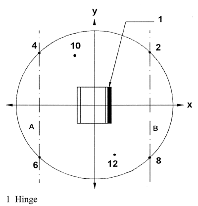
Test No 2: Complete opening of the lidU.K.
To minimise his influence on the measurements, the operator shall stand at the back side of the container (hinge side) for the four-wheel containers, or on the right side of the container (between microphone position 10 and microphone position 12) for the two-wheel containers. The lid shall be released by its middle or as near as possible to its middle
To prevent any moving of the container, wheels shall be locked during the test. For the two-wheel containers, and to prevent any bounce of the container, the operator can maintain it by placing his hand on the top rim
The measurement is carried out during the following cycle:
initially, the lid is opened horizontally
the lid is released without giving an impulse
after complete opening, and before a possible rebond, the lid is raised to its initial position
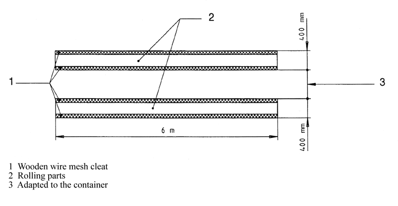
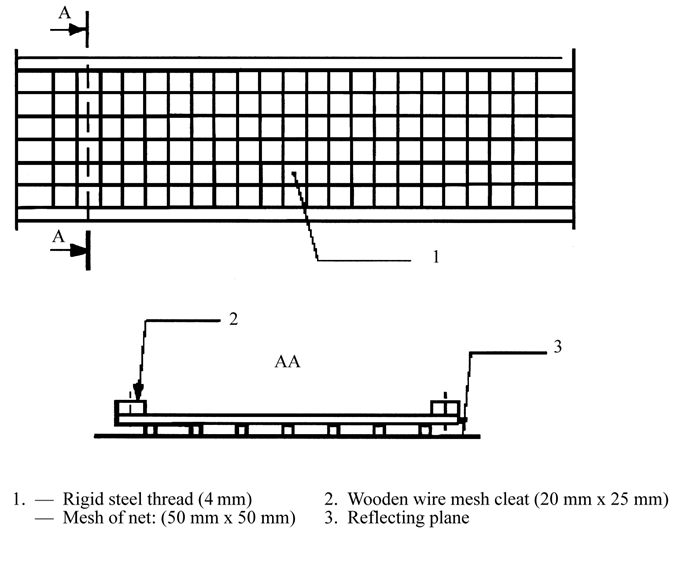
Test No 3: Rolling of the container over an artificial irregular trackU.K.
For this test, an artificial test track, simulating irregular ground is used. This test track consists of two parallel strips of steel mesh (6 m long and 400 mm wide), fastened in the reflecting plane approximately every 20 cm. The distance between the two strips is adapted according to the type of container, in order to allow the wheels to roll all over the whole length of the track. The mounting conditions shall ensure a flat surface. If necessary, the track is fastened on the ground with resilient material to avoid emission of parasitic noise
Note:U.K.
Every strip can be composed of several 400 mm wide elements fitted togetherU.K.
An example of adequate track is given in Figures 39.1 and 39.2
The operator is situated at the lid hinge side
The measurement is carried out while the operator draws the container along the artificial track, with a constant speed of approximately 1 m/s, between points A and B (4,24 m distance — see Figure 39.3) when the wheel axle, for a 2-wheel container, or the first wheel axle for a 4-wheel container, reaches point A or point B. This procedure is repeated three times in each direction
During the test, for a 2-wheel container, the angle between the container and the track shall be 45°. For a 4-wheel container, the operator shall ensure an appropriate contact of all the wheels with the track.
Period(s) of observation/determination of resulting sound power level if more than one operating condition is usedU.K.
Test Nos 1 and 2: Free shutting down of the lid along the container body and complete opening of the lidU.K.
If possible, the measurements are carried out simultaneously at the six microphone positions. Otherwise, the sound levels measured at each microphone position will be classified in increasing order and the sound power levels are calculated by associating the values at each microphone position according to their row
The A-weighted single-event sound pressure level is measured for each of the 20 shuttings and the 20 openings of the lid at each measurement point. The sound power levels L WAshutting and L WAopening are calculated from the quadratic mean of the five highest values among those obtained
Test No 3: Rolling the container over an artificial irregular trackU.K.
The period of observation T shall be equal to the duration necessary to cover the distance between point A and point B on the track.
The sound power level L WArolling is equal to the mean of six values differing by less than 2 dB. If this criterion is not fulfilled with six measurements, the cycle is repeated as far as necessary
The resulting sound power level is calculated by:

40.MOTOR HOESU.K.
See No 32
The tool shall be disconnected during measurement
41.PAVER-FINISHERSU.K.
Basic noise emission standardU.K.
EN ISO 3744:1995
Operating conditions during testU.K.
Test under loadU.K.
| The engine of the machine shall operate at the nominal speed indicated by the manufacturer. All working units shall be activated and operate at the following speeds: | |
| conveying system | at least 10 % of maximum value |
| spreading system | at least 40 % of maximum value |
| tamper (speed, stroke) | at least 50 % of maximum value |
| vibrators (speed, unbalance moment) | at least 50 % of maximum value |
| pressure bars (frequency, pressure) | at least 50 % of maximum value |
Period of observationU.K.
The period of observation shall at least be 15 seconds
42.PILING EQUIPMENTU.K.
Basic noise emission standardU.K.
EN ISO 3744:1995
Test areaU.K.
ISO 6395:1988
Operating conditions during testU.K.
Test under loadU.K.
The piling equipment is installed at the top of a pile which has sufficient resistance in the ground to allow the equipment to work at a steady speed. In the case of impact hammers, the cap must be supplied with a new, wooden filling. The head of the pile is 0,50 m above the test area
Period of observationU.K.
The period of observation shall at least be 15 seconds
43.PIPELAYERSU.K.
See No 0
44.PISTE CATERPILLARSU.K.
See No 0
45.POWER GENERATORSU.K.
Basic noise emission standardU.K.
EN ISO 3744:1995
Environmental correction K2A U.K.
Measurement in the open airU.K.
K 2A = 0
Measurement indoorsU.K.
The value of the constant K 2A, determined without artificial surface and in accordance with Annex A to EN ISO 3744:1995, shall be ≤ 2,0 dB, in which case K 2A shall be disregarded
Measurement surface/number of microphone positions/measuring distanceU.K.
Hemisphere/6 microphone positions according to Part A item 5/according to Part A item 5. If l > 2 m: a parallelepiped according to EN ISO 3744:1995 may be used with measuring distance d = 1 m.
Operating conditions during testU.K.
Mounting of equipmentU.K.
The power generators shall be installed on the reflecting plane; skid-mounted power generators shall be placed on a support 0,40 m high, unless otherwise required by the manufacturer's conditions of installation
Test under loadU.K.
ISO 8528-10:1998, point 9
Period of observationU.K.
The period of observation shall at least be 15 seconds
46.POWER SWEEPERSU.K.
Basic noise emission standardU.K.
EN ISO 3744:1995
Operating conditions during testU.K.
Test under loadU.K.
The power sweeper shall be tested in a stationary position. The engine and auxiliary units operate at the speed provided by the manufacturer for the operation of the working equipment; the broom operates at its highest speed, it is not in contact with the ground; the suction system shall work at its maximum suction power with the distance between ground and mouth of the suction system not exceeding 25 mm
Period of observationU.K.
The period of observation shall at least be 15 seconds
47.REFUSE COLLECTION VEHICLESU.K.
Basic noise emission standardU.K.
EN ISO 3744:1995
Operating conditions during testU.K.
Test under loadU.K.
The refuse collection vehicle shall be tested in a stationary position for the following operating conditions.
1.
The engine is running at maximum speed provided by the manufacturer. The equipment shall not be running. This test is not carried out for vehicles with electrical supply only
2.
The compaction system is running
The refuse collection vehicle and the hopper receiving the waste are empty
If the engine speed is automatically accelerated when the compaction system is running, this value shall be measured. If the measured value is lower than the speed provided by the manufacturer by more than 5 % the test is carried out with the engine accelerated by the cab accelerator, to ensure the engine speed provided by the manufacturer
If the engine speed for the compaction system is not provided by the manufacturer or if the vehicle is not provided with an automatic accelerator, then the engine speed, issued by the cab accelerator shall be 1 200 rpm
3.
The lifting device is running up and down, without load and without container. The engine speed is obtained and controlled as for the compaction system running (point 2)
4.
Material is falling into the refuse collection vehicle
Materials are emptied in bulk with the lifting device into the hopper (initially empty). A two-wheeled container with a 240 l capacity, complying with EN 840-1:1997 shall be used for this operation. If the lifting device is not able to pick up such a container, a container with a capacity close to 240 l shall be used. The material shall consist of 30 tubes of PVC, each with a 0,4 kg approximate mass and with the following dimensions:
length: 150 mm ± 0,5 mm
nominal external diameter: 90 mm + 0,3/- 0 mm
nominal depth: 6,7 mm + 0,9/- 0 mm
Period(s) of observation/determination of resulting sound power level if more than one operating condition is usedU.K.
The period of observation shall be:
1.
at least 15 seconds. The resulting sound power level shall be L WA1
2.
at least three complete cycles, if the compaction system is running automatically. If the compaction system is not running automatically, but cycle by cycle, measurements are carried out at least during three cycles. The resulting sound power level (L WA2) shall be the root mean square value of the three (or more) measurements
3.
at least three continuous complete work-cycles, including the entirety of lifting device up and lifting device down. The resulting sound power level (L WA3) shall be the root mean square value of the three (or more) measurements
4.
at least three complete work-cycles, each including the falling of 30 tubes into the hopper. Each cycle shall not exceed 5 seconds. For these measurements L pAeq,T is replaced by L pA,1s. The resulting sound power level (L WA4) shall be the root mean square value of the three (or more) measurements.
The resulting sound power level is calculated by:

Note:U.K.
In the case of a refuse collection vehicle only electrically supplied, the coefficient associated to L WA1 is assumed to be equal to 0.U.K.
48.ROAD MILLING MACHINESU.K.
Basic noise emission standardU.K.
EN ISO 3744:1995
Operating conditions during testU.K.
Mounting of equipmentU.K.
The longitudinal axis of the road milling machine shall be parallel to the y-axis
Test under loadU.K.
The road milling machine shall be brought to its steady state within the range specified in the instructions supplied to the purchaser. The engine and all attachments shall be running at their respective rated speeds in the idling mode
Period of observationU.K.
The period of observation shall at least be 15 seconds
49.SCARIFIERSU.K.
Basic noise emission standardU.K.
EN ISO 3744:1995
Test areaU.K.
ISO 11094:1991
In case of dispute, measurements shall be carried out in the open air on the artificial surface (Point 4.1.2 of ISO 11094:1991)
Environmental correction K2A U.K.
Measurement in the open airU.K.
K 2A = 0
Measurements indoorsU.K.
The value of the constant K 2A, determined without artificial surface and in accordance with Annex A to EN ISO 3744:1995, shall be ≤ 2,0 dB, in which case K 2A shall be disregarded
Measurement surface/number of microphone positions/measuring distanceU.K.
ISO 11094:1991
Operating conditions during testU.K.
Test under loadU.K.
The scarifier shall be operated with the engine at its nominal speed and its working device idling (operating, but not ripping)
Period of observationU.K.
The period of observation shall at least be 15 seconds
50.SHREDDERS/CHIPPERSU.K.
Basic noise emission standardU.K.
EN ISO 3744:1995
Test areaU.K.
ISO 11094:1991
Environmental correction K2A U.K.
Measurement in the open airU.K.
K 2A = 0
Measurements indoorsU.K.
The value of the constant K 2A, determined without artificial surface and in accordance with Annex A to EN ISO 3744:1995, shall be ≤ 2,0 dB, in which case K 2A shall be disregarded.
Measurement surface/number of microphone positions/measuring distanceU.K.
ISO 11094:1991
Operating conditions during testU.K.
Test under loadU.K.
The shredder/chipper shall be tested chipping one or more pieces of wood
The work-cycle consists of chipping a round piece of wood (dry pine or plywood) of at least 1,5 m length, that is sharpened at one end and has a diameter approximately equal to the maximum that the shredder/chipper is designed to accept specified in the instructions supplied to the purchaser
Period of observation/determination of resulting sound power levelU.K.
The period of observation shall end when there is no more material in the chipping area, but it shall not exceed 20 seconds. If both operation conditions are possible, the higher sound power level has to be given
51.SNOW REMOVING MACHINES WITH ROTATING TOOLSU.K.
Basic noise emission standardU.K.
EN ISO 3744:1995
Operating conditions during testU.K.
Test under loadU.K.
The snow blower shall be tested in a stationary position. The snow blower shall, according to the manufacturer's recommendations, operate with the working equipment at its maximum speed and the engine at the corresponding speed
Period of observationU.K.
The period of observation shall at least be 15 seconds
52.SUCTION VEHICLESU.K.
Basic noise emission standardU.K.
EN ISO 3744:1995
Operating conditions during testU.K.
Test under loadU.K.
The suction vehicle shall be tested in a stationary position. The engine and auxiliary units operate at the speed provided by the manufacturer for the operation of the working equipment; the vacuum pump(s) is (are) operating at its (their) maximum speed provided by the manufacturer. The suction equipment is operated in such a way that the internal pressure is equal to atmospheric pressure (0 % vacuum). The flow noise of the suction nozzle shall not have any influence on the results of the measurements
Period of observationU.K.
The period of observation shall at least be 15 seconds
53.TOWER CRANESU.K.
Basic noise emission standardU.K.
EN ISO 3744:1995
Measurement surface/number of microphone positions/measuring distanceU.K.
Measurements at ground-levelU.K.
Hemisphere/6 microphone positions according to Part A paragraph 5/according to Part A paragraph 5.
Measurements carried out at jib-heightU.K.
Where the lifting mechanism is located at the jib-height, the measurement surface shall be a sphere of 4 m radius, the centre of which shall coincide with the geometrical centre of the winch
Where the measurement is carried out with the lifting mechanism on the jib stay of the crane, the area of measurement surface is a sphere; S is equal to 200 m2
The microphone positions shall be as follows (see figure 53.1):
Four microphone positions on a horizontal plane passing through the geometric centre of the mechanism (H = h/2)
with L = 2,80 m
and d = 2,80 - l/2
L = half-distance between two consecutive microphone positions
l = length of mechanism (along axis of jib)
b = width of mechanism
h = height of mechanism
d = distance between microphone support and mechanism in direction of jib
The other two microphone positions shall be located at the points of intersection of the sphere and the vertical line passing through the geometric centre of the mechanism
Operating conditions during testU.K.
Mounting of equipmentU.K.
Measurement of lifting mechanismU.K.
The lifting mechanism during the test shall be mounted in one of the following ways. The position shall be described in the test report
(a)
Lifting mechanism at ground level
The mounted crane shall be placed on a flat reflecting surface of concrete or non-porous asphalt
(b)
Lifting mechanism on the jib stay
The lifting mechanism shall be at least 12 m above the ground
(c)
Lifting mechanism fixed to the ground
The lifting mechanism shall be fixed to a flat reflecting surface of concrete or non-porous asphalt
Measurement of the energy generatorU.K.
Where the energy generator is attached to the crane, whether or not it is linked to the lifting mechanism, the crane shall be mounted on a flat reflecting surface of concrete or non-porous asphalt
Where the lifting mechanism is situated on the jib stay, the noise measurement may be carried out with the mechanism either mounted on the jib stay or fixed to the ground
Where the energy source powering the crane is independent from it (electrical power generator or mains, or hydraulic or pneumatic power source), only the noise level of the mechanism winch shall be measured
Where the energy generator is attached to the crane, the energy generator and the lifting mechanism shall be measured separately if they are not combined. Where these two devices are combined, the measurement shall refer to the whole assembly
During the test the lifting mechanism and the energy generator shall be installed and used in accordance with the manufacturer's instructions
Test free of loadU.K.
The energy generator incorporated in the crane shall operate at the full power rating indicated by the manufacturer
The lifting mechanism shall operate free of load, with its drum turning at the rotation speed corresponding to the maximum hook-displacement speed, in the raising and lowering modes. This speed shall be specified by the manufacturer. The greater of the two sound power levels (raising or lowering) shall be used for the results of the test
Test under loadU.K.
The energy generator incorporated in the crane shall operate at the full power rating indicated by the manufacturer. The lifting mechanism shall operate with a cable tension at the drum corresponding to the maximum load (for the minimum radius) with the hook moving at the maximum speed. The load and speed figures shall be specified by the manufacturer. The speed shall be checked during the test
Period(s) of observation/determination of resulting sound power level if more than one operating condition is usedU.K.
For the measurement of the sound pressure level of the lifting mechanism, the measuring period shall be (t r+ t f ) seconds:
t r
being the period in seconds prior to activation of the brake, with the lifting mechanism operating in the manner specified above. For the purpose of the test t r = 3 seconds
t f
being the period in seconds between the moment when the brake is activated and that when the hook comes to a complete standstill
If an integrator is used, the integration period shall be equal to (t r + t f) seconds
The root mean square value at a microphone position i shall be given by:

L ri
being the sound pressure level at microphone position i during period t r
L fi
being the sound pressure level at microphone position i during breaking period t f
Figure 53.1
Arrangement of microphone positions where the lifting mechanism is located on the jib stay

54.TRENCHERSU.K.
See No 0
55.TRUCK MIXERSU.K.
Basic noise emission standardU.K.
EN ISO 3744:1995
Operating conditions during testU.K.
Test under loadU.K.
The truck mixer shall be tested in a stationary position. The drum is filled with concrete of medium consistency (propagation measure 42 to 47 cm) complying to the rated capacity. The engine driving the drum shall operate at the speed that causes the maximum speed of the drum specified in the instructions supplied to the purchaser
Period of observationU.K.
The period of observation shall at least be 15 seconds
56.WATER PUMP UNITSU.K.
Basic noise emission standardU.K.
EN ISO 3744:1995
Measurement surface/number of microphone positions/measuring distanceU.K.
Parallelepiped/according to EN ISO 3744:1995 with measurement distance d = 1 m
Operating conditions during testU.K.
Mounting of equipmentU.K.
The water pump unit shall be installed on the reflecting plane; skid-mounted water pump units shall be placed on a support 0,40 m high, unless otherwise required by the manufacturer's conditions of installation
Test under loadU.K.
The engine must operate at the point of best efficiency given in the manufacturer's instructions
Period of observationU.K.
The period of observation shall at least be 15 seconds
57.WELDING GENERATORSU.K.
Basic noise emission standardU.K.
EN ISO 3744:1995
Environmental correction K2A U.K.
Measurement in the open airU.K.
K 2A = 0
Measurement indoorsU.K.
The value of the constant K 2A, determined in accordance with Annex A to EN ISO 3744:1995, shall be ≤ 2,0 dB, in which case K 2A shall be disregarded
Measurement surface/number of microphone positions/measuring distanceU.K.
Hemisphere/6 microphone positions according to Part A item 5/according to Part A item 5
If l > 2 m: a parallelepiped according to EN ISO 3744:1995 may be used with measuring distance d = 1 m
Operating conditions during testU.K.
Mounting of equipmentU.K.
The welding generators shall be installed on the reflecting plane; skid-mounted welding generators shall be placed on a support 0,40 m high, unless otherwise required by the manufacturer's conditions of installation
Test under loadU.K.
ISO 8528-10:1998, point 9
Period of observationU.K.
The period of observation shall at least be 15 seconds
(1)
Net power means the power in ‘EC kW’ obtained on the test bench at the end of the crankshaft, or its equivalent, measured in accordance with the EC method of measuring the power of internal combustion engines for road vehicles, except that the power of the engine cooling fan is excluded.
Options/Help
Print Options
PrintThe Whole Directive
PrintThis Annex only
You have chosen to open the Whole Directive
The Whole Directive you have selected contains over 200 provisions and might take some time to download. You may also experience some issues with your browser, such as an alert box that a script is taking a long time to run.
Would you like to continue?
You have chosen to open Schedules only
The Schedules you have selected contains over 200 provisions and might take some time to download. You may also experience some issues with your browser, such as an alert box that a script is taking a long time to run.
Would you like to continue?
Legislation is available in different versions:
Latest Available (revised):The latest available updated version of the legislation incorporating changes made by subsequent legislation and applied by our editorial team. Changes we have not yet applied to the text, can be found in the ‘Changes to Legislation’ area.
Original (As adopted by EU): The original version of the legislation as it stood when it was first adopted in the EU. No changes have been applied to the text.
See additional information alongside the content
Geographical Extent: Indicates the geographical area that this provision applies to. For further information see ‘Frequently Asked Questions’.
Show Timeline of Changes: See how this legislation has or could change over time. Turning this feature on will show extra navigation options to go to these specific points in time. Return to the latest available version by using the controls above in the What Version box.
Opening Options
Different options to open legislation in order to view more content on screen at once
More Resources
Access essential accompanying documents and information for this legislation item from this tab. Dependent on the legislation item being viewed this may include:
- the original print PDF of the as adopted version that was used for the EU Official Journal
- lists of changes made by and/or affecting this legislation item
- all formats of all associated documents
- correction slips
- links to related legislation and further information resources
Timeline of Changes
This timeline shows the different versions taken from EUR-Lex before exit day and during the implementation period as well as any subsequent versions created after the implementation period as a result of changes made by UK legislation.
The dates for the EU versions are taken from the document dates on EUR-Lex and may not always coincide with when the changes came into force for the document.
For any versions created after the implementation period as a result of changes made by UK legislation the date will coincide with the earliest date on which the change (e.g an insertion, a repeal or a substitution) that was applied came into force. For further information see our guide to revised legislation on Understanding Legislation.
More Resources
Use this menu to access essential accompanying documents and information for this legislation item. Dependent on the legislation item being viewed this may include:
- the original print PDF of the as adopted version that was used for the print copy
- correction slips
Click 'View More' or select 'More Resources' tab for additional information including:
- lists of changes made by and/or affecting this legislation item
- confers power and blanket amendment details
- all formats of all associated documents
- links to related legislation and further information resources
 All content is available under the Open Government Licence v3.0 except where otherwise stated. This site additionally contains content derived from EUR-Lex, reused under the terms of the Commission Decision 2011/833/EU on the reuse of documents from the EU institutions. For more information see the EUR-Lex public statement on re-use.