- Latest available (Revised)
- Original (As adopted by EU)
Commission Regulation (EU) 2018/1832Show full title
Commission Regulation (EU) 2018/1832 of 5 November 2018 amending Directive 2007/46/EC of the European Parliament and of the Council, Commission Regulation (EC) No 692/2008 and Commission Regulation (EU) 2017/1151 for the purpose of improving the emission type approval tests and procedures for light passenger and commercial vehicles, including those for in-service conformity and real-driving emissions and introducing devices for monitoring the consumption of fuel and electric energy (Text with EEA relevance)
You are here:
- Regulations originating from the EU
- 2018 No. 1832
- Whole Regulation
- Previous
- Next

What Version
Advanced Features
- Show Geographical Extent(e.g. England, Wales, Scotland and Northern Ireland)
- Show Timeline of Changes
More Resources
Revised version PDFs
- Revised 27/11/20185.04 MB
Legislation originating from the EU
When the UK left the EU, legislation.gov.uk published EU legislation that had been published by the EU up to IP completion day (31 December 2020 11.00 p.m.). On legislation.gov.uk, these items of legislation are kept up-to-date with any amendments made by the UK since then.


This item of legislation originated from the EU
Legislation.gov.uk publishes the UK version. EUR-Lex publishes the EU version. The EU Exit Web Archive holds a snapshot of EUR-Lex’s version from IP completion day (31 December 2020 11.00 p.m.).
Changes over time for: Commission Regulation (EU) 2018/1832
Changes to legislation:
This version of this Regulation was derived from EUR-Lex on IP completion day (31 December 2020 11:00 p.m.). It has not been amended by the UK since then. Find out more about legislation originating from the EU as published on legislation.gov.uk.
Changes to Legislation
Revised legislation carried on this site may not be fully up to date. At the current time any known changes or effects made by subsequent legislation have been applied to the text of the legislation you are viewing by the editorial team. Please see ‘Frequently Asked Questions’ for details regarding the timescales for which new effects are identified and recorded on this site.
Commission Regulation (EU) 2018/1832
of 5 November 2018
amending Directive 2007/46/EC of the European Parliament and of the Council, Commission Regulation (EC) No 692/2008 and Commission Regulation (EU) 2017/1151 for the purpose of improving the emission type approval tests and procedures for light passenger and commercial vehicles, including those for in-service conformity and real-driving emissions and introducing devices for monitoring the consumption of fuel and electric energy
(Text with EEA relevance)
THE EUROPEAN COMMISSION,
Having regard to the Treaty on the Functioning of the European Union,
Having regard to Regulation (EC) No 715/2007 of the European Parliament and of the Council of 20 June 2007 on type approval of motor vehicles with respect to emissions from light passenger and commercial vehicles (Euro 5 and Euro 6) and on access to vehicle repair and maintenance information(1), and in particular Articles 5(3) and 14(3) thereof,
Having regard to Directive 2007/46/EC of the European Parliament and of the Council of 5 September 2007 establishing a framework for the approval of motor vehicles and their trailers, and of systems, components and separate technical units intended for such vehicles (Framework Directive)(2), and in particular Article 39(2) thereof,
Whereas:
(1) Regulation (EC) No 715/2007 is a separate act under the type-approval procedure laid down by Directive 2007/46/EC. It requires new light passenger and commercial vehicles to comply with certain emission limits and lays down additional requirements on access to vehicle repair and maintenance information. The specific technical provisions necessary to implement that Regulation are contained in Commission Regulation (EU) 2017/1151(3), which replaces and repeals Commission Regulation (EC) No 692/2008(4).
(2) Some of the effects of Commission Regulation (EC) No 692/2008 remain until it is repealed as from 1 January 2022. However, it is necessary to clarify that such effects include the possibility to request extensions of existing type-approvals granted under this Regulation.
(3) By Regulation (EU) 2017/1151, a new regulatory test procedure implementing the Worldwide Harmonised Light Vehicles Test Procedure (WLTP) was introduced into Union legislation. The WLTP contains stricter and more detailed conditions for the execution of the emissions tests at type approval.
(4) In addition, by Commission Regulations (EU) 2016/427(5), (EU) 2016/646(6) and (EU) 2017/1154(7) a new methodology for testing vehicle emissions in real-driving conditions, the RDE test procedure, was introduced.
(5) In order for the WLTP test to be possible, some margin of tolerance is necessary. However, the test tolerance should not be exploited to obtain results different from those associated with the execution of the test at set-point conditions. Therefore, in order to provide a level playing field among different vehicle manufacturers and to ensure that the measured CO2 and fuel consumption values are more in line with real life, a method to normalise the impact of specific test tolerances on CO2 and fuel consumption test results should be introduced.
(6) The fuel and/or electric energy consumption values resulting from the regulatory laboratory test procedures should be complemented by information on the vehicles' average real-world consumption when used on the road. Such information, once anonymised, collected and aggregated, is essential for assessing that the regulatory test procedures adequately reflect the average real world CO2 emissions as well as the fuel and/or electric energy consumed. Moreover, the availability at the vehicle of instantaneous fuel consumption information should facilitate on-road testing.
(7) To ensure a timely assessment of the representativeness of the new regulatory test procedures, in particular for vehicles with large market shares, the scope of the new requirements for on-board fuel consumption monitoring should be in a first instance limited to conventional and hybrid vehicles running on liquid fuels and to plug-in hybrid vehicles, as these are to-date the only powertrains covered by corresponding technical standards.
(8) The quantity of fuel and/or electric energy used is already being determined and stored on board of most new vehicles; however, the devices presently used to monitor this information are not subject to standardised requirements. In order to ensure that the data provided by these devices are accessible and may serve as a harmonised basis for a comparison between different vehicle categories and manufacturers, basic type-approval requirements with regard to the devices should be laid down.
(9) Regulation (EU) 2016/646 introduced the requirement for the manufacturers to declare the use of auxiliary emission strategies. In addition, Regulation (EU) 2017/1154 increased the supervision of emission strategies by the type approval authorities. However, the application of those requirements has highlighted the need to harmonise the application of the rules on auxiliary emission strategies by the different type approval authorities. Therefore it is appropriate to lay down a common format for the extended documentation package and a common methodology for the assessment of auxiliary emission strategies.
(10) The decision to allow access, if requested, to the manufacturer's extended documentation package should be left to the national authorities and therefore the confidentiality clause linked to this document should be deleted from Regulation (EU) 2017/1151. This deletion should be without prejudice to the uniform application of the legislation throughout the Union, as well as the possibility for all parties to access all relevant information for conducting RDE testing.
(11) After the introduction of the RDE tests at the stage of type approval, it is now necessary to update the rules on in-service conformity checks in order to ensure that the real driving emissions are also effectively limited during the normal life of the vehicles under normal conditions of use.
(12) The application of the new RDE during in-service conformity checks will require more resources for the performance of the in-service conformity testing of a vehicle and the evaluation of its results. In order to balance the need to perform effective in-service conformity tests with the increased testing burden, the maximum number of vehicles in a statistical sample and the pass and fail criteria for the sample applicable to all in-service conformity testing should be adapted.
(13) In-service conformity checks currently cover only pollutant emissions measured through the Type 1 test. However, in order to ensure that the requirements of Regulation (EC) No 715/2007 are met, they should be extended to tailpipe and evaporative emissions. Therefore, Type 4 and Type 6 tests should be introduced for the purposes of in-service conformity tests. Due to the cost and complexity of such tests, they should remain optional.
(14) A review of the current in-service conformity tests, performed by the manufacturers, revealed that very few fails were reported to type approval authorities although recall campaigns and other voluntary actions related to emissions were implemented by the manufacturers. Therefore, it is necessary to introduce more transparency and control in the in-service conformity checks.
(15) In order to control the in-service conformity process more effectively, type approval authorities should be responsible for performing tests and checks on a percentage of the approved vehicle types each year.
(16) In order to facilitate the information flows generated by in-service conformity testing, as well as to assist type-approval authorities in the decision making process, an electronic platform should be developed by the Commission.
(17) In order to improve the vehicle selection process for the testing by type-approval authorities, information is needed that could identify potential problems and vehicle types with high emissions. Remote sensing, simplified on-board emissions monitoring systems (SEMS) and testing with portable emission measurement systems (PEMS) should be recognised as valid tools for providing information to the type-approval authorities that can guide the selection of vehicles to test.
(18) Ensuring the quality of the in-service conformity tests is essential. It is therefore necessary to lay down the rules on the accreditation of testing laboratories.
(19) In order to allow testing, all relevant information needs to be publicly accessible. In addition, some of the information needed for the performance of in-service conformity checks should be easily available and should therefore be indicated in the certificate of conformity.
(20) In order to increase the transparency of the in-service conformity process, type approval authorities should be required to publish an annual report with the results of their in-service conformity checks.
(21) The methodologies prescribed in order to ensure that only trips made under normal conditions be considered valid RDE tests led to too many invalid tests and should therefore be reviewed and simplified.
(22) A review of the methodologies for the evaluation of the pollutant emissions of a valid trip showed that the results of the two methods currently allowed are not consistent. A new simple and transparent methodology should therefore be laid down. The evaluation factors used in the new methodology should be kept under constant assessment by the Commission in order to reflect the actual state of the technology.
(23) The use of plug-in hybrids, which are used partly in electric mode and partly with the internal combustion engine, should be duly taken into account for the purposes of RDE testing and therefore the calculated RDE emissions should reflect that advantage.
(24) A new evaporative emissions test procedure has been developed at the level of the United Nations Economic Commission for Europe (UN/ECE) which takes into account the technological progress in the control of evaporative emissions from petrol (gasoline) vehicles, adapts that procedure to the WLTP test procedure and introduces new provisions for sealed tanks. It is therefore appropriate to update the current Union rules on evaporative emissions tests to reflect the changes at the level of the UN/ECE.
(25) Also under the auspices of the UN/ECE, the WLTP test procedure has been further improved and complemented with a series of new elements, including alternative ways to measure the road load parameters of a vehicle, more clear provisions for bi-fuel vehicles, improvements of the CO2 interpolation method, updates related to dual-axis dynamometer requirements and tyre rolling resistances. Those new developments should now be incorporated into Union legislation.
(26) The practical experience with the application of the WLTP since its mandatory introduction for new vehicle types in the Union on 1 September 2017 has shown that this procedure should be further adapted to the Union type-approval system, in particular as regards the information to be included in the relevant documentation.
(27) The changes in the type-approval documentation resulting from the amendments in this Regulation need to be reflected also in the certificate of conformity and the whole vehicle type-approval documentation in Directive 2007/46/EC.
(28) It is therefore appropriate to amend Regulation (EU) 2017/1151, Regulation (EC) No 692/2008 and Directive 2007/46/EC accordingly.
(29) The measures provided for in this Regulation are in accordance with the opinion of the Technical Committee — Motor Vehicles,
HAS ADOPTED THIS REGULATION:
Article 1U.K.Amendments to Regulation (EU) 2017/1151
Regulation (EU) 2017/1151 is amended as follows:
(1)
Article 2 is amended as follows:
(a)
point 1(b) is replaced by the following:
‘(b)fall in a single “CO2 interpolation range” within the meaning of point 2.3.2 of Sub-Annex 6 to Annex XXI;’;
(b)
point 6 is replaced by the following:
‘(6)
“periodically regenerating system” means an exhaust emissions control device (e.g. catalytic converter, particulate trap) that requires a periodic regeneration process;’;
(c)
points 11 and 12 are replaced by the following:
‘(11)
“bi-fuel vehicle” means a vehicle with two separate fuel storage systems that is designed to run primarily on only one fuel at a time;
(12)
“bi-fuel gas vehicle” means a bi-fuel vehicle where the two fuels are petrol (petrol mode) and either LPG, NG/biomethane, or hydrogen;’;
(d)
the following point 33 is inserted:
‘(33)
“pure ICE vehicle” means a vehicle where all of the propulsion energy converters are internal combustion engines;’;
(e)
point 38 is replaced by the following:
‘(38)
“rated engine power” (Prated) means the maximum net power of the engine or motor in kW measured in accordance with the requirements of Annex XX;’;
(f)
points 45 to 48 are replaced by the following:
‘(45)
“Fuel tank system” means the devices which allow storing the fuel, comprising the fuel tank, the fuel filler, the filler cap and the fuel pump when it is fitted in or on the fuel tank;
(46)
“permeability factor” (PF) means the factor determined on the basis of hydrocarbon losses over a period of time and used to determine the final evaporative emissions;
(47)
“monolayer non-metal tank” means a fuel tank constructed with a single layer of non-metal material including fluorinated/sulfonated materials;
(48)
“multilayer tank” means a fuel tank constructed with at least two different layered materials, one of which is a hydrocarbon barrier material;’;
(2)
Article 3 is amended as follows:
(1)
paragraph 1 is replaced by the following:
‘1.In order to receive an EC type-approval with regard to emissions and vehicle repair and maintenance information, the manufacturer shall demonstrate that the vehicles comply with the requirements of this Regulation when tested in accordance with the test procedures specified in Annexes IIIA to VIII, XI, XIV, XVI, XX, XXI and XXII. The manufacturer shall also ensure that the reference fuels comply with the specifications set out in Annex IX.’;
(2)
paragraph 7 is replaced by the following:
‘7.For the Type 1 test set out in Annex XXI, vehicles that are fuelled with LPG or NG/biomethane shall be tested in the Type 1 test for variation in the composition of LPG or NG/biomethane, as set out in Annex 12 to UN/ECE Regulation No 83 for pollutant emissions, with the fuel used for the measurement of the net power in accordance with Annex XX to this Regulation.
Vehicles that can be fuelled both with petrol or LPG or NG/biomethane shall be tested on both the fuels, tests on LPG or NG/biomethane being performed for variation in the composition of LPG or NG/biomethane, as set out in Annex 12 to UN/ECE Regulation No 83, and with the fuel used for the measurement of the net power in accordance with Annex XX to this Regulation.’;
(3)
the following Article 4a is inserted:
‘Article 4aRequirements for type-approval regarding devices for monitoring the consumption of fuel and/or electric energy
The manufacturer shall ensure that the following vehicles of categories M1 and N1 are equipped with a device for determining, storing and making available data on the quantity of fuel and/or electric energy used for the operation of the vehicle:
(1)
pure ICE and Not-Off-Vehicle Charging Hybrid Electric vehicles (NOVC-HEVs) powered exclusively by mineral diesel, biodiesel, petrol, ethanol or any combination of these fuels;
(2)
Off-Vehicle Charging Hybrid Electric Vehicles (OVC-HEVs) powered by electricity and any of the fuels mentioned in point 1.
The device for monitoring the consumption of fuel and/or electric energy shall comply with the requirements laid down in Annex XXII.’;
(4)
Article 5 is amended as follows:
(a)
paragraph 11 is amended as follows:
(a)
the second subparagraph is replaced by the following:
‘The extended documentation package shall be identified and dated by the approval authority and kept by that authority for at least 10 years after the approval is granted.’;
(b)
the following third to sixth subparagraphs are added:
‘At the request of the manufacturer, the approval authority shall conduct a preliminary assessment of the AES for new vehicle types. In that case, the relevant documentation shall be provided to the type approval authority between 2 and 12 months before the start of the type-approval process.
The approval authority shall make a preliminary assessment on the basis of the extended documentation package, as described in point (b) of Appendix 3a to Annex I, provided by the manufacturer. The approval authority shall make the assessment in accordance with the methodology described in Appendix 3b of Annex I. The approval authority may deviate from that methodology in exceptional and duly justified cases.
The preliminary assessment of the AES for new vehicle types shall remain valid for the purposes of type approval for a period of 18 months. That period may be extended by a further 12 months if the manufacturer provides to the approval authority proof that no new technologies have become accessible in the market that would change the preliminary assessment of the AES.
A list of AES which were deemed non-acceptable by Type Approval Authorities shall be compiled yearly by the Type-Approval Authorities Expert Group (TAAEG) and made available to the public by the Commission.’;
(b)
The following paragraph 12 is inserted:
‘12.The manufacturer shall also provide the type approval authority which granted the emission type-approval under this Regulation (“granting approval authority”) with a package on Testing Transparency containing the necessary information in order to allow the performance of testing in accordance with point 5.9 of Part B of Annex II.’;
(5)
Article 9 is amended as follows:
(a)
paragraphs 2 to 6 are replaced by the following:
‘2.The in-service conformity checks shall be appropriate for confirming that tailpipe and evaporative emissions are effectively limited during the normal life of vehicles under normal conditions of use.
3.In-service conformity shall be checked on properly maintained and used vehicles, in accordance with Appendix 1 of Annex II, between 15 000 km or 6 months whichever occurs later and 100 000 km or 5 years whichever occurs sooner. In service conformity for evaporative emissions shall be checked on properly maintained and used vehicles, in accordance with Appendix 1 of Annex II, between 30 000 km or 12 months whichever occurs later and 100 000 km or 5 years whichever occurs sooner.
The requirements for in-service conformity checks are applicable until 5 years after the last Certificate of Conformity or individual approval certificate is issued for vehicles of that in-service conformity family.
4.In-service conformity checks shall not be mandatory if the annual sales of the in-service conformity family are less than 5 000 vehicles in the Union for the previous year. For such families, the manufacturer shall provide the approval authority with a report of any emissions related warranty, repair claim and OBD fault as set out in point 4.1 of Annex II. Such in-service conformity families may still be selected to be tested in accordance with Annex II.
5.The manufacturer and the granting type approval authority shall perform in-service conformity checks in accordance with Annex II.
6.The granting approval authority shall take the decision on whether a family failed the provisions of in-service conformity, following a compliance assessment and approve the plan of remedial measures presented by the manufacturer in accordance with Annex II.’;
(b)
the following paragraphs 7 and 8 are added:
‘7.If a type approval authority has established that an in-service conformity family fails the in-service conformity check, it shall notify without delay the granting type approval authority, in accordance with Article 30(3) of Directive 2007/46/EC.
Following that notification and subject to the provisions of Article 30(6) of Directive 2007/46/EC, the granting approval authority shall inform the manufacturer that an in-service conformity family fails the in-service conformity checks and that the procedures described in points 6 and 7 of Annex II shall be followed.
If the granting approval authority establishes that no agreement can be reached with a type approval authority that has established that an in-service conformity family fails the in-service conformity check, the procedure pursuant to Article 30(6) of Directive 2007/46/EC shall be initiated.
8.In addition to points 1 to 7, the following shall apply to vehicles type approved according to Part B of Annex II.
(a)Vehicles submitted to multi-stage type-approval, as defined in Article 3(7) of Directive 2007/46/EC, shall be checked for in service conformity in accordance with the rules for multistage approval set out in point 5.10.6 of Part B of Annex II to this Regulation.
(b)Armoured vehicles, hearses and wheelchair accessible vehicles, as defined in points 5.2 and 5.5 of Part A of Annex II to Directive 2007/46/EC respectively, shall not be subject to the provisions of this Article. All other special purpose vehicles as defined in point 5 of Part A of Annex II to Directive 2007/46/EC, shall be checked for in service conformity in accordance with the rules for multistage type-approvals set out in Part B of Annex II to this Regulation.’;
(6)
Article 15 is amended as follows:
(a)
in paragraph 2, the second subparagraph is replaced by the following:
‘With effect from 1 September 2019, national authorities shall refuse, on grounds relating to emissions or fuel consumption, to grant EC type approval or national type approval, in respect to new vehicle types which do not comply with Annex VI. At the request of the manufacturer, until 31 August 2019 the evaporative emissions test procedure set out in Annex 7 to UNECE Regulation 83 or the evaporative emissions test procedure set out in in Annex VI of Regulation (EC) No 692/2008 may still be used for the purposes of type-approval under this Regulation.’;
(b)
in paragraph 3 the following subparagraph is added:
‘With the exception of vehicles approved for evaporative emissions under the procedure laid down in Annex VI of Regulation (EC) No 692/2008, with effect from 1 September 2019, national authorities shall prohibit the registration, sale or entry into service of new vehicles that do not comply with Annex VI of this Regulation.’;
(c)
in paragraph 4, points (d) and (e) are deleted;
(d)
paragraph 5 is amended as follows:
(i)
point (b) is replaced by the following:
‘(b)With respect to vehicles of a WLTP interpolation family which fulfil the extension rules specified in point 3.1.4 of Annex I of Regulation (EC) No 692/2008, procedures performed in accordance with Section 3.13 of Annex III to Regulation (EC) No 692/2008 until 3 years after the dates given in Article 10(4) of Regulation (EC) No 715/2007 shall be accepted by the approval authority for the purposes of fulfilling the requirements of Appendix 1 to Sub-Annex 6 to Annex XXI of this Regulation.;’
(ii)
the following is added in point (c):
‘For the purposes of this point, the possibility to use test results from procedures performed and completed in accordance with Regulation (EC) No 692/2008 shall only be applicable to those vehicles of a WLTP interpolation family which fulfil the extension rules specified in point 3.3.1 of Annex I of Regulation (EC) No 692/2008’
(e)
the following paragraphs 8 to 11 are added
‘8.Part B of Annex II shall apply to categories M1, M2 and category N1 class I based on types approved from 1 January 2019, and for category N1 class II and III and category N2 based on types approved from 1 September 2019. It shall also apply to all vehicles registered from 1 September 2019 for categories M1, M2 and category N1 class I, and to all vehicles registered from 1 September 2020 for category N1 class II and III and category N2. In all other cases Part A of Annex II shall apply.
9.With effect from 1 January 2020 in the case of vehicles as referred to in Article 4a of categories M1 and N1, class I, and from 1 January 2021 in the case of vehicles as referred to in Article 4a of category N1 vehicles, classes II and III, national authorities shall refuse, on grounds relating to emissions or fuel consumption, to grant EC type approval or national type approval in respect of new vehicle types which do not meet the requirements laid down in Article 4a.
With effect from 1 January 2021, in the case vehicles as referred to in Article 4a of categories M1 and N1, class I, and from 1 January 2022 in the case of vehicles as referred to in Article 4a of category N1 vehicles, classes II and III, national authorities shall prohibit the registration, sale or entry into service of new vehicles that do not comply with that Article.
10.With effect from 1 September 2019 national authorities shall prohibit the registration, sale or entry into service of new vehicles that do not comply with the requirements set out in Annex IX of the Directive 2007/46/EC as amended by Commission Regulation (EU) 2018/1832(8).
For all vehicles registered between 1 January and 31 August 2019 under new type approvals granted in the same period and where the information listed in Annex IX of the Directive 2007/46/EC as amended by Regulation (EU) 2018/1832 is not yet included in the Certificate of Conformity, the manufacturer shall make this information available free-of-charge within 5 working days of the request by an accredited lab or technical service for the purposes of testing under Annex II.
11.The requirements of Article 4a shall not apply to type approvals granted to small volume manufacturers.’;
(7)
Article 18bis is deleted;
(8)
Annex I is amended as set out in Annex I to this Regulation;
(9)
Annex II is amended as set out in Annex II to this Regulation;
(10)
Annex IIIA is amended as set out in Annex III to this Regulation;
(11)
in Annex V, point 2.3 is replaced by the following:
‘2.3.The road load coefficients to be used shall be those for vehicle low (VL). If VL does not exist, then the VH road load shall be used. VL and VH are defined in point 4.2.1.1.2 of Sub-Annex 4 to Annex XXI. Alternatively, the manufacturer may choose to use road loads that have been determined in accordance with the provisions of Appendix 7 to Annex 4a of UN/ECE Regulation No 83 for a vehicle included in the interpolation family.’;
(12)
Annex VI is replaced by the text in Annex IV to this Regulation;
(13)
Annex VII is amended as follows:
(1)
in point 2.2, in the table, in the legend, the deterioration factor designation ‘P’ is replaced by ‘PN’;
(2)
point 3.10 is replaced by the following
‘3.10.The road load coefficients to be used shall be those for vehicle low (VL). If VL does not exist or the total load of vehicle (VH) at 80 km/h is higher than the total load of VL at 80 km/h + 5 %, then the VH road load shall be used. VL and VH are defined in point 4.2.1.1.2 of Sub-Annex 4 to Annex XXI.’;
(14)
in Annex VIII, point 3.3 is replaced by the following:
‘3.3.The road load coefficients to be used shall be those for vehicle low (VL). If VL does not exist then the VH road load shall be used. VL and VH are defined in point 4.2.1.1.2 of Sub-Annex 4 to Annex XXI. Alternatively the manufacturer may choose to use road loads that have been determined in accordance with the provisions of Appendix 7 of Annex 4a of UN/ECE Regulation No 83 for a vehicle included in the interpolation family. In both cases, the dynamometer shall be adjusted to simulate the operation of a vehicle on the road at – 7 °C. Such adjustment may be based on a determination of the road load force profile at – 7 °C. Alternatively, the driving resistance determined may be adjusted for a 10 % decrease of the coast-down time. The technical service may approve the use of other methods for determining the driving resistance.’;
(15)
Annex IX is amended as set out in Annex V to this Regulation;
(16)
Annex XI is replaced by the text in Annex VI to this Regulation;
(17)
Annex XII is amended as set out in Annex VII to this Regulation;
(18)
in Annex XIV, in Appendix 1, the words ‘Annex I, Section 2.3.1 and 2.3.5 of Implementing Regulation (EU) 2017/1151’ are replaced by the words ‘Annex I, Section 2.3.1 and 2.3.4 of Regulation (EU) 2017/1151’;
(19)
Annex XVI is replaced by the text in Annex VIII to this Regulation;
(20)
Annex XXI is amended as set out in Annex IX to this Regulation;
(21)
Annex XXII, as set out in Annex X to this Regulation, is added.
Article 2U.K.Amendment to Regulation (EC) No 692/2008
Regulation (EC) No 692/2008 is amended as follows:
(1)
in the first subparagraph of Article 16a of Regulation (EC) No 692/2008, the following point (d) is added:
‘(d)extensions to type-approvals granted under this Regulation, until new requirements become applicable for new vehicles’;
(2)
in Annex 1, Appendix 3 the following point 3.2.12.2.5.7 is added:
‘3.2.12.2.5.7.Permeability factor (1): …’;
(3)
in Annex XII, point 4.4 is deleted.
Article 3U.K.Amendments to Directive 2007/46/EC
Annexes I, III, VIII, IX and XI to Directive 2007/46/EC are amended as set out in Annex XI to this Regulation.
Article 4U.K.Entry into force
This Regulation shall enter into force on the twentieth day following that of its publication in the Official Journal of the European Union.
It shall apply from 1 January 2019.
This Regulation shall be binding in its entirety and directly applicable in all Member States.
ANNEX IU.K.
Annex I to Regulation (EU) 2017/1151 is amended as follows:
(1)
the following point 1.1.3. is inserted:
‘1.1.3.For LPG or NG, the fuel to be used shall be the one selected by the manufacturer for the measurement of the net power in accordance with Annex XX to this Regulation. The selected fuel shall be specified in the information document set out in Appendix 3 of Annex I to this Regulation.’;
(2)
points 2.3.1., 2.3.2. and 2.3.3. are replaced by the following:
‘2.3.1.Any vehicle with an emission control computer shall include features to deter modification, except as authorised by the manufacturer. The manufacturer shall authorise modifications if those modifications are necessary for the diagnosis, servicing, inspection, retrofitting or repair of the vehicle. Any reprogrammable computer codes or operating parameters shall be resistant to tampering and afford a level of protection at least equivalent to that afforded by the provisions of the standard ISO 15031-7:2013. Any removable calibration memory chips shall be potted, encased in a sealed container or protected by electronic algorithms and shall not be changeable without the use of specialised tools and procedures. Only features directly associated with emissions calibration or prevention of vehicle theft may be so protected.
2.3.2.Computer-coded engine operating parameters shall not be changeable without the use of specialised tools and procedures (e.g. soldered or potted computer components or sealed (or soldered) enclosures).
2.3.3.At the request of the manufacturer, the approval authority may grant exemptions to the requirements in points 2.3.1. and 2.3.2. for those vehicles that are unlikely to require protection. The criteria that the approval authority shall evaluate in considering an exemption shall include, but are not limited to, the current availability of performance chips, the high-performance capability of the vehicle and the projected sales volume of the vehicle.’;
(3)
the following points 2.3.4., 2.3.5. and 2.3.6. are inserted:
‘2.3.4.Manufacturers using programmable computer code systems shall take the necessary measures to deter unauthorised reprogramming. Such measures shall include enhanced tamper protection strategies and write-protect features requiring electronic access to an off-site computer maintained by the manufacturer, to which independent operators shall also have access using the protection afforded in point 2.3.1. and point 2.2. of Annex XIV. Methods giving an adequate level of tamper protection shall be approved by the approval authority.
2.3.5.In the case of mechanical fuel-injection pumps fitted to compression-ignition engines, manufacturers shall take adequate steps to protect the maximum fuel delivery setting from tampering while a vehicle is in service.
2.3.6.Manufacturers shall effectively deter reprogramming of the odometer readings, in the board network, in any powertrain controller as well as in the transmitting unit for remote data exchange if applicable. Manufacturers shall include systematic tamper-protection strategies and write-protect features to protect the integrity of the odometer reading. Methods giving an adequate level of tamper protection shall be approved by the approval authority.’;
(4)
point 2.4.1. is replaced by the following:
‘2.4.1.Figure I.2.4 illustrates the application of the tests for type-approval of a vehicle. The specific test procedures are described in Annexes II, IIIA, IV, V, VI, VII, VIII, XI, XVI, XX, XXI and XXII.
Figure I.2.4 Application of test requirements for type-approval and extensions
| a Specific test procedures for hydrogen and flex fuel biodiesel vehicles will be defined at a later stage. | |||||||||||
| b Particulate mass and particle number limits and respective measurement procedures shall apply only to vehicles with direct injection engines | |||||||||||
| c When a bi-fuel vehicle is combined with a flex fuel vehicle, both test requirements are applicable. | |||||||||||
| d Only NOx emissions shall be determined when the vehicle is running on hydrogen. | |||||||||||
| e The particle number RDE test only applies to vehicles for which Euro 6 PN emission limits are defined in Table 2 of Annex I to Regulation (EC) No 715/2007.’ | |||||||||||
| Vehicle category | Vehicles with positive ignition engines including hybridsa b | Vehicles with compression ignition engines including hybrids | Pure electric vehicles | Hydrogen fuel cell vehicles | |||||||
|---|---|---|---|---|---|---|---|---|---|---|---|
| Mono fuel | Bi-fuelc | Flex-fuelc | |||||||||
| Reference fuel | Petrol (E10) | LPG | NG/Biomethane | Hydrogen (ICE) | Petrol (E10) | Petrol (E10) | Petrol (E10) | Petrol (E10) | Diesel (B7) | — | Hydrogen (Fuel Cell) |
| LPG | NG/Biomethane | Hydrogen (ICE)d | Ethanol (E85) | ||||||||
| Gaseous pollutants (Type 1 test) | Yes | Yes | Yes | Yesd | Yes (both fuels) | Yes (both fuels) | Yes (both fuels) | Yes (both fuels) | Yes | — | — |
| PM (Type 1 test) | Yes | — | — | — | Yes (petrol only) | Yes (petrol only) | Yes (petrol only) | Yes (both fuels) | Yes | — | — |
| PN | Yes | — | — | — | Yes (petrol only) | Yes (petrol only) | Yes (petrol only) | Yes (both fuels) | Yes | — | — |
| Gaseous pollutants, RDE (Type 1A test) | Yes | Yes | Yes | Yesd | Yes (both fuels) | Yes (both fuels) | Yes (both fuels) | Yes (both fuels) | Yes | — | — |
| PN, RDE (Type 1A test)e | Yes | — | — | — | Yes (petrol only) | Yes (petrol only) | Yes (petrol only) | Yes (both fuels) | Yes | — | — |
| ATCT (14 °C test) | Yes | Yes | Yes | Yesd | Yes (both fuels) | Yes (both fuels) | Yes (both fuels) | Yes (both fuels) | Yes | — | — |
| Idle emissions (Type 2 test) | Yes | Yes | Yes | — | Yes (both fuels) | Yes (both fuels) | Yes (petrol only) | Yes (both fuels) | — | — | — |
| Crankcase emissions (Type 3 test) | Yes | Yes | Yes | — | Yes (petrol only) | Yes (petrol only) | Yes (petrol only) | Yes (petrol only) | — | — | — |
| Evaporative emissions (Type 4 test) | Yes | — | — | — | Yes (petrol only) | Yes (petrol only) | Yes (petrol only) | Yes (petrol only) | — | — | — |
| Durability (Type 5 test) | Yes | Yes | Yes | Yes | Yes (petrol only) | Yes (petrol only) | Yes (petrol only) | Yes (petrol only) | Yes | — | — |
| Low temperature emissions (Type 6 test) | Yes | — | — | — | Yes (petrol only) | Yes (petrol only) | Yes (petrol only) | Yes (both fuels) | — | — | — |
| In-service conformity | Yes | Yes | Yes | Yes | Yes (as at type approval) | Yes (as at type approval) | Yes (as at type approval) | Yes (both fuels) | Yes | — | — |
| On-board diagnostics | Yes | Yes | Yes | Yes | Yes | Yes | Yes | Yes | Yes | — | — |
| CO2 emissions, fuel consumption, electric energy consumption and electric range | Yes | Yes | Yes | Yes | Yes (both fuels) | Yes (both fuels) | Yes (both fuels) | Yes (both fuels) | Yes | Yes | Yes |
| Smoke opacity | — | — | — | — | — | — | — | — | Yes | — | — |
| Engine power | Yes | Yes | Yes | Yes | Yes | Yes | Yes | Yes | Yes | Yes | Yes |
(5)
point 3.1.1. is replaced by the following:
‘3.1.1.The type-approval shall be extended to vehicles if they conform to the criteria of Article 2 (1) or if they conform to Article 2 (1) (a) and (c) and fulfil all the following criteria:
(a)
the CO2 emission of the tested vehicle resulting from step 9 of Table A7/1 of Sub-Annex 7 to Annex XXI is less than or equal to the CO2 emission obtained from the interpolation line corresponding to the cycle energy demand of the tested vehicle;
(b)
the new interpolation range does not exceed the maximum range as set out in point 2.3.2.2. of Sub-Annex 6 to Annex XXI;
(c)
the pollutant emissions respect the limits set out in Table 2 of Annex I to Regulation (EC) No 715/2007.’;
(6)
the following point 3.1.1.1. is inserted:
‘3.1.1.1.The type-approval shall not be extended to create an interpolation family if it has been granted only in relation to Vehicle High.’;
(7)
in point 3.1.2. the first paragraph below the title is replaced by the following:
‘For Ki tests undertaken under Appendix 1 to Sub-Annex 6 to Annex XXI (WLTP), the type-approval shall be extended to vehicles if they conform to the criteria of paragraph 5.9. of Annex XXI.’
(8)
Point 3.2.inclusive of all its sub-points is replaced by the following:
‘3.2. Extensions for evaporative emissions (type 4 test)
3.2.1.For tests performed in accordance with Annex 6 to UN/ECE Regulation No 83 [1 day NEDC] or the Annex to Regulation (EC) No 2017/1221 [2 days NEDC] the type-approval shall be extended to vehicles equipped with a control system for evaporative emissions which meet the following conditions:
3.2.1.1.
The basic principle of fuel/air metering (e.g. single point injection) is the same.
3.2.1.2.
The shape of the fuel tank is identical and the material of the fuel tank and liquid fuel hoses are technically equivalent.
3.2.1.3.
The worst-case vehicle with regard to the cross-section and approximate hose length shall be tested. Whether non-identical vapour/liquid separators are acceptable is decided by the technical service responsible for the type-approval tests.
3.2.1.4.
The fuel tank volume is within a range of ± 10 %.
3.2.1.5.
The setting of the fuel tank relief valve is identical.
3.2.1.6.
The method of storage of the fuel vapour is identical, i.e. trap form and volume, storage medium, air cleaner (if used for evaporative emission control), etc.
3.2.1.7.
The method of purging of the stored vapour is identical (e.g. air flow, start point or purge volume over the preconditioning cycle).
3.2.1.8.
The method of sealing and venting of the fuel metering system is identical.
3.2.2.For tests performed according Annex VI [2 days WLTP] the type-approval shall be extended to vehicles equipped with a control system for evaporative emissions which meet the requirements of point 5.5.1. of Annex VI.
3.2.3.The type-approval shall be extended to vehicles with:
3.2.3.1.
different engine sizes;
3.2.3.2.
different engine powers;
3.2.3.3.
automatic and manual gearboxes;
3.2.3.4.
two and four wheel transmissions;
3.2.3.5.
different body styles; and
3.2.3.6.
different wheel and tyre sizes.’;
(9)
point 4.1.2. is replaced by the following:
‘4.1.2.The manufacturer shall check the conformity of production by testing the emissions of pollutants (given in Table 2 of Annex I to Regulation (EC) No 715/2007), the emission of CO2 (along with the measurement of electric energy consumption, EC and, where applicable, the monitoring of the OBFCM device accuracy), the crankcase emissions, evaporative emissions and the OBD in accordance with the test procedures described in Annexes V, VI, XI, XXI and XXII. The verification shall therefore include the tests of types 1, 3, 4 and the test for OBD, as described in section 2.4.
The Type Approval Authority shall keep record for a period of at least 5 years of all the documentation related to the conformity of production test results and shall make it available to the Commission upon request.
The specific procedures for conformity of production are set out in Sections 4.2 to 4.7 and Appendixes 1 and 2.’;
(10)
point 4.1.3. is replaced by the following:
‘4.1.3.For the purposes of the manufacturer's conformity of production check, the family means the conformity of production (COP) family for tests of Type 1, including the monitoring of the OBFCM device accuracy, and Type 3, includes for the Type 4 test the extensions described in point 3.2 and the OBD family with the extensions described in point 3.4 for the OBD tests.’;
(11)
the following points 4.1.3.1, 4.1.3.1.1. and 4.1.3.1.2. are inserted:
‘4.1.3.1.COP family criteria
4.1.3.1.1.For Category M vehicles and for Category N1 class I and class II vehicles, the COP family shall be identical to the interpolation family, as described in paragraph 5.6. of Annex XXI.
4.1.3.1.2For Category N1 Class III and Category N2 vehicles, only vehicles that are identical with respect to the following vehicle/powertrain/transmission characteristics may be part of the same COP family:
(a)
Type of internal combustion engine: fuel type (or types in the case of flex-fuel or bi-fuel vehicles), combustion process, engine displacement, full-load characteristics, engine technology, and charging system, and also other engine subsystems or characteristics that have a non-negligible influence on CO2 mass emission under WLTP conditions;
(b)
Operation strategy of all CO2 mass emission influencing components within the powertrain;
(c)
Transmission type (e.g. manual, automatic, CVT) and transmission model (e.g. torque rating, number of gears, number of clutches, etc.);
(d)
Number of powered axles.’;
(12)
point 4.1.4. is replaced by the following:
‘4.1.4.The frequency for product verification performed by the manufacturer shall be based on a risk assessment methodology consistent with the international standard ISO 31000:2018 — Risk Management — Principles and guidelines and at least for Type 1 with a minimum frequency per COP family of one verification per 5 000 vehicles produced or once per year, whichever comes first.’;
(13)
in point 4.1.5., the third paragraph is replaced by the following:
‘If the approval authority is not satisfied with the auditing procedure of the manufacturer, physical test shall directly be carried out on production vehicles as described in points 4.2 to 4.7.’
(14)
in point 4.1.6., in the first paragraph, the second sentence is replaced by the following:
‘The approval authority shall conduct these physical emission tests and OBD tests on production vehicles as described in points 4.2 to 4.7.’
(15)
points 4.2.1. and 4.2.2. are replaced by the following:
‘4.2.1.The Type 1 test shall be carried out on production vehicles of a valid member of the COP family as described in point 4.1.3.1. The test results shall be the values after all corrections according to this Regulation are applied. The limit values against which to check conformity for pollutants are set out in Table 2 of Annex I to Regulation (EC) No 715/2007. As regards CO2 emissions, the limit value shall be the value determined by the manufacturer for the selected vehicle in accordance with the interpolation methodology set out in Sub-Annex 7 of Annex XXI. The interpolation calculation shall be verified by the approval authority.
4.2.2.A sample of three vehicles shall be selected at random in the COP family. After selection by the approval authority, the manufacturer shall not undertake any adjustment to the vehicles selected.’;
(16)
point 4.2.2.1. is deleted;
(17)
in point 4.2.3., the second and third paragraphs are replaced by the following;
‘4.2.3.The statistical method for calculating the test criteria is described in Appendix 1.
The production of a COP family shall be deemed to not conform when a fail decision is reached for one or more of the pollutants and CO2 values, in accordance with the test criteria in Appendix 1.
The production of a COP family shall be deemed to conform once a pass decision is reached for all the pollutants and CO2 values in accordance with the test criteria in Appendix 1.’;
(18)
point 4.2.4. is replaced by the following;
‘4.2.4.At the request of the manufacturer and with the acceptance of the approval authority, tests may be carried out on a vehicle of the COP family with a maximum of 15 000 km in order to establish measured evolution coefficients EvC for pollutants/CO2 for each COP family. The running-in procedure shall be conducted by the manufacturer, who shall not to make any adjustments to these vehicles.’;
(19)
in point 4.2.4.1. (c), the introductory part is replaced by the following;
‘(c)the other vehicles in the COP family shall not be run in, but their zero km emissions/EC/CO2 shall be multiplied by the evolution coefficient of the first run-in vehicle. In this case, the values to be taken for testing as in Appendix 1 shall be:’;
(20)
point 4.4.3.3. is replaced by the following:
‘4.4.3.3.The value determined in accordance with point 4.4.3.2. shall be compared to the value determined in accordance with point 2.4. of Appendix 2.’;
(21)
Appendix 1 is amended as follows:
(a)
point 1. is replaced by the following:
‘1.This Appendix describes the procedure to be used to verify the production conformity requirements for the Type 1 test for pollutants/CO2, including conformity requirements for PEVs and OVC-HEVs, and to monitor the OBFCM device accuracy.’;
(b)
in point 2., the first paragraph is replaced by the following:
‘Measurements of the pollutants specified in Table 2 of Annex I to Regulation (EC) No 715/2007, and the emission of CO2 shall be carried out on a minimum number of 3 vehicles, and consecutively increase until a pass or fail decision is reached. The OBFCM device accuracy shall be determined for each of the N tests.’
(c)
in point 3.(iii), after the introductory part, the text
‘A × L – VAR/L ≤ Xtests < A × L – ((N – 3)/13) × VAR/L’
is replaced by the following:
‘A × L – VAR/L ≤ Xtests ≤ A × L – ((N – 3)/13) × VAR/L’
(d)
in point 4.(iii), after the introductory part, the text
‘A – VAR ≤ Xtests < A – ((N – 3)/13) × VAR’
is replaced by the following:
‘A – VAR ≤ Xtests ≤ A – ((N – 3)/13) × VAR’
(e)
in point 4., the last paragraph is deleted.
(f)
the following point 5. is added:
‘5.For vehicles referred to in Article 4a, the accuracy of the OBFCM device shall be calculated as follows:
xi,OBFCM
=
accuracy of the OBFCM device determined for each single test i in accordance with the formulae point 4.2 of Annex XXII.
The Type Approval authority shall keep a record of the determined accuracies for each COP family tested.’;
(23)
Appendix 2 is amended as follows:
(a)
in point 1.2., the words ‘paragraph 1.1.2.3. of Sub-Annex 6 of Annex XXI’ are replaced by the words ‘paragraph 1.2.3. of Sub-Annex 6 to Annex XXI’
(b)
in point 2.3., the words ‘paragraph 4.1.1. of Annex XXI’ are replaced by the words ‘paragraph 4.1.1. of Sub-Annex 8 to Annex XXI’
(c)
in point 2.4., the words ‘paragraph 1.1.2.3. of Sub-Annex 6 to Annex XXI’ are replaced by the words ‘paragraph 1.2.3. of Sub-Annex 6 to Annex XXI’;
(24)
Appendix 3 is amended as follows:
(a)
the following points 0.2.2.1. to 0.2.3.9. are inserted:
‘0.2.2.1.Allowed Parameter Values for multistage type approval to use the base vehicle emission values (insert range if applicable):
Final Vehicle mass in running order (in kg): …
Frontal area for final vehicle (in cm2): …
Rolling resistance (kg/t): …
Cross-sectional area of air entrance of the front grille (in cm2): …
0.2.3.Identifiers:
0.2.3.1.interpolation family's identifier: …
0.2.3.2.ATCT family's identifier: …
0.2.3.3.PEMS family's identifier: …
0.2.3.4.Roadload family's identifier
0.2.3.4.1.Roadload family of VH: …
0.2.3.4.2.Roadload family of VL: …
0.2.3.4.3.Roadload families applicable in the interpolation family: …
0.2.3.5.Roadload Matrix family's identifier: …
0.2.3.6.Periodic regeneration family's identifier: …
0.2.3.7.Evaporative test family's identifier: …
0.2.3.8.OBD family's identifier: …
0.2.3.9.other family's identifier: …’;
(b)
point 2.6.(b) is deleted.
(c)
the following point 2.6.3. is inserted:
‘2.6.3.Rotational mass: 3 % of the sum of mass in running order and 25 kg or value, per axle (kg): …’;
(d)
point 3.2.2.1. is replaced by the following:
‘3.2.2.1.Diesel/Petrol/LPG/NG or Biomethane/Ethanol (E 85)/Biodiesel/Hydrogen (1), (6)’;
(e)
point 3.2.12.2.5.5. is replaced by the following:
‘3.2.12.2.5.5.Schematic drawing of the fuel tank (petrol and ethanol engines only): …’;
(f)
the following points 3.2.12.2.5.5.1. to 3.2.12.2.5.5.5. are inserted:
‘3.2.12.2.5.5.1.Fuel tank system capacity, material and construction: …
3.2.12.2.5.5.2.Description of vapour hose material, fuel line material and connection technique of the fuel system: …
3.2.12.2.5.5.3.Sealed tank system: yes/no
3.2.12.2.5.5.4.Description of fuel tank relief valve setting (air ingestion and relief): …
3.2.12.2.5.5.5.Description of the purge control system: …’;
(g)
point 3.2.12.2.5.6. is replaced by the following:
‘3.2.12.2.5.6.Description and schematic of the heat shield between tank and exhaust system: …’;
(j)
point 3.2.19.4.1. is deleted;
(m)
the following points 3.2.20.2.5., 3.2.20.2.5.1., 3.2.20.2.5.2., 3.2.20.2.5.3. and 3.2.20.2.6. are inserted:
‘3.2.20.2.5.Worst case approach vehicle cool down: yes/no (1)
3.2.20.2.5.1.(not worst case approach) Minimum soaking time, tsoak_ATCT (hours): …
3.2.20.2.5.2.(not worst case approach) Location of the engine temperature measurement: …
3.2.20.2.6.Single interpolation family within the ATCT family approach: yes/no (1)’;
(n)
the following point 3.3. is inserted:
‘3.3.Electric machine
3.3.1.Type (winding, excitation): …
3.3.1.1.Maximum hourly output: … kW
(manufacturer's declared value)
3.3.1.1.1.Maximum net power (a) … kW
(manufacturer's declared value)
3.3.1.1.2.Maximum 30 minutes power (a) … kW
(manufacturer's declared value)
3.3.1.2.Operating voltage:… V
3.3.2.REESS
3.3.2.1.Number of cells: …
3.3.2.2.Mass: … kg
3.3.2.3.Capacity: … Ah (Amp-hours)
3.3.2.4.Position: …’;
(o)
points 3.5.7.1. and 3.5.7.1.1. are replaced by the following:
‘3.5.7.1.Test vehicle parameters
| a Representative vehicle is tested for the road load matrix family. | |||||
| Vehicle | Vehicle Low (VL)if existing | Vehicle High(VH) | VMif existing | V representative (only for road load matrix familya) | Default values |
|---|---|---|---|---|---|
| Vehicle bodywork type | — | ||||
| Road load method used (measurement or calculation by road load family) | — | — | |||
| Road load information: | |||||
| Tyres make and type, if measurement | — | ||||
| Tyre dimensions (front/rear), if measurement | — | ||||
| Tyre rolling resistance (front/rear) (kg/t) | |||||
| Tyre pressure (front/rear) (kPa), if measurement | |||||
| Delta CD × A of vehicle L compared to vehicle H (IP_H minus IP_L) | — | — | — | ||
| Delta CD × A compared to road load family vehicle L (IP_H/L minus RL_L), if calculation by road load family | — | — | |||
| Vehicle test mass (kg) | |||||
| Road load coefficients | |||||
| f0 (N) | |||||
| f1 (N/(km/h)) | |||||
| f2 (N/(km/h)2) | |||||
| Frontal area m2 (0,000 m2) | — | — | — | ||
| Cycle Energy Demand (J) | |||||
3.5.7.1.1.Fuel used for the Type 1 test and selected for the measurement of the net power in accordance with Annex XX to this Regulation (for LPG or NG vehicles only): …’;
(p)
points 3.5.7.1.1.1. to 3.5.7.1.3.2.3. are deleted;
(q)
points 3.5.7.2.1. to 3.5.7.2.1.2.0. are replaced by the following:
‘3.5.7.2.1.CO2 mass emission for pure ICE vehicles and NOVC-HEVs
3.5.7.2.1.0.Minimum and maximum CO2 values within the interpolation family
3.5.7.2.1.1.Vehicle high: … g/km
3.5.7.2.1.1.0.Vehicle high (NEDC): … g/km
3.5.7.2.1.2.Vehicle low (if applicable): … g/km
3.5.7.2.1.2.0.Vehicle low (if applicable) (NEDC): … g/km
3.5.7.2.1.3.Vehicle M (if applicable): … g/km
3.5.7.2.1.3.0.Vehicle M (if applicable) (NEDC): … g/km’;
(r)
points 3.5.7.2.2. to 3.5.7.2.2.3.0. are replaced by the following:
‘3.5.7.2.2.Charge-Sustaining CO2 mass emission for OVC-HEVs
3.5.7.2.2.1.Charge Sustaining CO2 mass emission vehicle high: g/km
3.5.7.2.2.1.0.Combined CO2 mass emission vehicle high (NEDC Condition B): g/km
3.5.7.2.2.2.Charge Sustaining CO2 mass emission vehicle low (if applicable): g/km
3.5.7.2.2.2.0.Combined CO2 mass emission vehicle low (if applicable) (NEDC Condition B): g/km
3.5.7.2.2.3.Charge Sustaining CO2 mass emission vehicle M (if applicable): g/km
3.5.7.2.2.3.0.Combined CO2 mass emission vehicle M (if applicable) (NEDC Condition B): g/km’;
(s)
points 3.5.7.2.3. to 3.5.7.2.3.3.0. are replaced with the following:
‘3.5.7.2.3.Charge Depleting CO2 mass emission and weighted CO2 mass emission for OVC-HEVs
3.5.7.2.3.1.Charge Depleting CO2 mass emission of Vehicle high: … g/km
3.5.7.2.3.1.0.Charge Depleting CO2 mass emission of Vehicle high (NEDC Condition A): … g/km
3.5.7.2.3.2.Charge Depleting CO2 mass emission of Vehicle low (if applicable): … g/km
3.5.7.2.3.2.0.Charge Depleting CO2 mass emission of Vehicle low (if applicable) (NEDC Condition A): … g/km
3.5.7.2.3.3.Charge Depleting CO2 mass emission of Vehicle M (if applicable): … g/km
3.5.7.2.3.3.0.Charge Depleting CO2 mass emission of Vehicle M (if applicable) (NEDC Condition A): … g/km’;
(t)
the following point 3.5.7.2.3.4. is added:
‘3.5.7.2.3.4.Minimum and maximum weighted CO2 values within the OVC interpolation family’;
(u)
point 3.5.7.4.3. is deleted;
(v)
point 3.5.8.3. is replaced by the following:
‘3.5.8.3.Emissions data related to the use of eco-innovations (repeat the table for each reference fuel tested) (w1)
| Total NEDC CO2 emissions saving (g/km)(w5) | |||||||
| Total WLTP CO2 emissions saving (g/km)(w5)’ | |||||||
| Decision approving the eco-innovation (w2) | Code of the eco-innovation (w3) | 1. CO2 emissions of the baseline vehicle (g/km) | 2. CO2 emissions of the eco-innovation vehicle (g/km) | 3. CO2 emissions of the baseline vehicle under type 1 test-cycle (w4) | 4. CO2 emissions of the eco-innovation vehicle under type 1 test-cycle | 5. Usage factor (UF), i.e. temporal share of technology usage in normal operation conditions | CO2 emissions savings ((1 – 2) – (3 – 4))*5 |
|---|---|---|---|---|---|---|---|
| xxxx/201x | |||||||
(x)
points 4.5.1.1., 4.5.1.2. and 4.5.1.3. are deleted;
(y)
in point 4.6., the word ‘Reverse’ at the bottom of the first column of the table, is deleted;
(z)
the following points 4.6.1. to 4.6.1.7.1. are inserted:
‘4.6.1.Gearshift
4.6.1.1.Gear 1 excluded: yes/no (1)
4.6.1.2.n_95_high for each gear: … min– 1
4.6.1.3.nmin_drive
4.6.1.3.1.1st gear: … min– 1
4.6.1.3.2.1st gear to 2nd: … min– 1
4.6.1.3.3.2nd gear to standstill: … min– 1
4.6.1.3.4.2nd gear: … min– 1
4.6.1.3.5.3rd gear and beyond: … min– 1
4.6.1.4.n_min_drive_set for acceleration/constant speed phases (n_min_drive_up): … min– 1
4.6.1.5.n_min_drive_set for deceleration phases (nmin_drive_down):
4.6.1.6.initial period of time
4.6.1.6.1.t_start_phase: … s
4.6.1.6.2.n_min_drive_start: … min– 1
4.6.1.6.3.n_min_drive_up_start: … min– 1
4.6.1.7.use of ASM: yes/no (1)
4.6.1.7.1.ASM values: …’;
(ab)
points 9.10.3. and 9.10.3.1 are deleted;
(ac)
the following points 12.8. to 12.8.3.2. are inserted:
‘12.8.Devices or systems with driver selectable modes which influence CO2 emissions and/or criteria emissions and do not have a predominant mode: yes/no (1)
12.8.1.Charge sustaining test (if applicable) (state for each device or system)
12.8.1.1.Best case mode: …
12.8.1.2.Worst case mode: …
12.8.2.Charge depleting test (if applicable) (state for each device or system)
12.8.2.1.Best case mode: …
12.8.2.2.Worst case mode: …
12.8.3.Type 1 test (if applicable) (state for each device or system)
12.8.3.1.Best case mode: …
12.8.3.2.Worst case mode: …’;
(ad)
in Appendix 3 the ‘Appendix to information document’ is deleted;
(23)
Appendix 3a is amended as follows:
(a)
point (d) is replaced by the following:
‘(d)detailed technical reasoning of any AES including a risk assessment estimating the risk with the AES and without it, and information on the following:
(i)
why any of the exception clauses from the defeat device prohibition in Article 5(2) of Regulation (EC) No 715/2007 apply;
(ii)
hardware element(s) that need to be protected by the AES, where applicable;
(iii)
proof of sudden and irreparable engine damage that cannot be prevented by regular maintenance and would occur in the absence of the AES, where applicable;
(iv)
a reasoned explanation on why there is a need to use an AES upon engine start, where applicable;’;
(b)
the following second and third paragraphs are added:
‘The extended documentation package shall be limited to 100 pages and shall include all the main elements to allow the type approval authority to assess the AES. The package may be complemented with annexes and other attached documents, containing additional and complementary elements, if necessary. The manufacturer shall send a new version of the extended documentation package to the type approval authority every time changes are introduced to the AES. The new version shall be limited to the changes and their effect. The new version of the AES shall be evaluated and approved by the type approval authority.
The extended documentation package shall be structured as follows:
Extended Documentation Package for AES Application No. YYY/OEM in accordance with Regulation (EU) 2017/1151
(24)
The following Appendix 3b is inserted:
‘Appendix 3bU.K. Methodology for the assessment of AES
The assessment of the AES by the type-approval authority shall include at least the following verifications:
(1)
The increase of emissions induced by the AES shall be kept at the lowest possible level:
(a)
The increase of total emissions when using an AES shall be kept at the lowest possible level throughout the normal use and life of the vehicles;
(b)
Whenever a technology or design that would allow for improved emission control is available on the market at the time of the AES preliminary assessment it shall be used with no unjustified modulation
(2)
When used to justify an AES, the risk of sudden and irreparable damage to the “propulsion energy converter and the drivetrain”, as defined in Mutual Resolution No. 2 (M.R.2) of the 1958 and 1998 Agreements of UNECE containing Vehicle Propulsion System Definitions(9), shall be appropriately demonstrated and documented, including the following information:
(a)
Proof of catastrophic (i.e. sudden and irreparable) engine damage shall be provided by the manufacturer, along with a risk assessment which includes an evaluation of the likelihood of the risk occurring and severity of the possible consequences, including results of tests carried out to this effect;
(b)
When a technology or design is available on the market at the time of the AES application that eliminates or reduces that risk, it shall be used to the largest extent technically possible (i.e. with no unjustified modulation);
(c)
Durability and the long-term protection of the engine or components of the emission control system from wear and malfunctioning shall not be considered an acceptable reason to grant an exemption from the defeat device prohibition.
(3)
An adequate technical description shall document why it is necessary to use an AES for the safe operation of the vehicle:
(a)
Proof of an increased risk to the safe operation of the vehicle should be provided by the manufacturer along with a risk assessment which includes an evaluation of the likelihood of the risk occurring and severity of the possible consequences, including results of tests carried out to this effect;
(b)
When a different technology or design is available on the market at the time of the AES application that would allow for lowering the safety risk, it shall be used to the largest extent technically possible (i.e. with no unjustified modulation).
(4)
An adequate technical description shall document why it is necessary to use an AES during engine start:
(a)
Proof of the need to use an AES during engine start shall be provided by the manufacturer along with a risk assessment which includes an evaluation of the likelihood of the risk occurring and severity of the possible consequences, including results of tests carried out to this effect;
(b)
Where a different technology or design is available on the market at the time of the AES application that would allow for improved emission control upon engine start, it shall be used to the largest extent technically possible.’
(25)
Appendix 4 is amended as follows:
(a)
in the model of EC type-approval certificate, in Section I, the following point 0.4.2. is inserted:
‘0.4.2.base vehicle (5a) (1): yes/no (1)’;
(b)
the Addendum to EC-type-approval certificate is amended as follows:
(i)
point 0. is replaced by the following:
‘0.Interpolation family identifier as defined in paragraph 5.0 of Annex XXI of Regulation (EU) 2017/1151.
0.1.Identifier: …
0.2.Base vehicle identifier (5a) (1): …’;
(ii)
points 1.1., 1.2. and 1.3. are replaced by the following:
‘1.1.Mass of the vehicle in running order:
VL (1): …
VH: …
1.2.Maximum mass:
VL (1): …
VH: …
1.3.Reference mass:
VL (1): …
VH: …’;
(iii)
point 2.1. is replaced by the following:
‘2.1.Tailpipe emissions test results
Emissions classification: …
Type 1 test results, where applicable
Type approval number if not parent vehicle (1): …
Test 1
| Type 1 Result | CO(mg/km) | THC(mg/km) | NMHC(mg/km) | NOx(mg/km) | THC + NOx(mg/km) | PM(mg/km) | PN(#.1011/km) |
|---|---|---|---|---|---|---|---|
| Measured (8) (9) | |||||||
| Ki × (8) (10) | (11) | ||||||
| Ki + (8) (10) | (11) | ||||||
| Mean value calculated with Ki (M × Ki or M + Ki) (9) | (12) | ||||||
| DF (+) (8) (10) | |||||||
| DF (×) (8) (10) | |||||||
| Final mean value calculated with Ki and DF (13) | |||||||
| Limit value |
Test 2 (if applicable)
Repeat Test 1 table with the second test results.
Test 3 (if applicable)
Repeat Test 1 table with the third test results.
Repeat Test 1, test 2 (if applicable) and test 3 (if applicable) for Vehicle Low (if applicable), and VM (if applicable)
ATCT test
| CO2 Emission (g/km) | Combined |
|---|---|
| ATCT (14 °C) MCO2,Treg | |
| Type 1 (23 °C) MCO2,23° | |
| Family correction factor (FCF) |
Difference between engine coolant end temperature and average soak area temperature of the last 3 hours ΔT_ATCT (°C) for the reference vehicle: …
The minimum soaking time tsoak_ATCT (s): …
Location of temperature sensor: …
ATCT family identifier: …
Type 2: (including data required for roadworthiness testing):
| Test | CO value(% vol) | Lambda (1) | Engine speed(min– 1) | Engine oil temperature(°C) |
|---|---|---|---|---|
| Low idle test | N/A | |||
| High idle test |
Type 3: …
Type 4: … g/test;
test procedure in accordance with: Annex 6 to UN/ECE Regulation No 83 [1 day NEDC] / the Annex to Regulation (EC) 2017/1221 [2 days NEDC] / Annex VI to Regulation (EU) 2017/1151 [2 days WLTP] (1).
Type 5:
Durability test: whole vehicle test/bench ageing test/none (1)
Deterioration factor DF: calculated/assigned (1)
Specify the values: …
Applicable Type 1 cycle (Sub-Annex 4 to Annex XXI of Regulation (EU) 2017/1151 or UN/ECE Regulation No 83) (14): …
| Type 6 | CO (g/km) | THC (g/km) |
|---|---|---|
| Measured value | ||
| Limit value’ |
(iv)
point 2.5.1. is replaced by the following:
‘2.5.1.Pure ICE vehicle and Not Externally Chargeable (NOVC) Hybrid Electric Vehicle’;
(v)
the following point 2.5.1.0. is inserted:
‘2.5.1.0.Minimum and maximum CO2 values within the interpolation family’;
(vi)
points 2.5.1.1.3. and 2.5.1.1.4. are replaced by the following:
‘2.5.1.1.3.CO2 mass emissions (provide values for each reference fuel tested, for the phases: the measured values, for the combined see points 1.2.3.8. and 1.2.3.9. of Sub-Annex 6 to Annex XXI of Regulation (EU) 2017/1151)
| CO2 Emission (g/km) | Test | Low | Medium | High | Extra High | Combined |
|---|---|---|---|---|---|---|
| MCO2,p,5 / MCO2,c,5 | 1 | |||||
| 2 | ||||||
| 3 | ||||||
| average | ||||||
| Final MCO2,p,H / MCO2,c,H | ||||||
2.5.1.1.4.Fuel consumption (provide values for each reference fuel tested, for the phases: the measured values for the combined see paragraphs 1.2.3.8 and 1.2.3.9 of Sub-Annex 6 to Annex XXI)
| Fuel consumption (l/100 km) or m3/100 km or kg/100 km (1) | Low | Medium | High | Extra High | Combined |
|---|---|---|---|---|---|
| Final values FCp,H/FCc,H’ |
(vii)
points 2.5.1.2. to 2.5.1.3. are replaced by the following:
‘2.5.1.2.Vehicle Low (if applicable)
2.5.1.2.1.Cycle Energy Demand: … J
2.5.1.2.2.Road load coefficients
2.5.1.2.2.1.f0, N: …
2.5.1.2.2.2.f1, N/(km/h): …
2.5.1.2.2.3.f2, N/(km/h) (2): …
2.5.1.2.3.CO2 mass emissions (provide values for each reference fuel tested, for the phases: the measured values for the combined see points 1.2.3.8. and.1.2.3.9. of Sub-Annex 6 to Annex XXI)
| CO2 Emission (g/km) | Test | Low | Medium | High | Extra High | Combined |
|---|---|---|---|---|---|---|
| MCO2,p,5/MCO2,c,5 | 1 | |||||
| 2 | ||||||
| 3 | ||||||
| average | ||||||
| Final MCO2,p,L/MCO2,c,L | ||||||
2.5.1.2.4.Fuel consumption (provide values for each reference fuel tested, for the phases: the measured values for the combined see points 1.2.3.8 and 1.2.3.9 of Sub-Annex 6 to Annex XXI)
| Fuel consumption (l/100 km) or m3/100 km or kg/100 km (1) | Low | Medium | High | Extra High | Combined |
|---|---|---|---|---|---|
| Final values FCp,L/FCc,L |
2.5.1.3.vehicle M for NOVC-HEV (if applicable)’;
(viii)
the following points 2.5.1.3.1. to 2.5.1.3.4. are inserted:
‘2.5.1.3.1.Cycle Energy Demand: … J
2.5.1.3.2.Road load coefficients
2.5.1.3.2.1.f0, N: …
2.5.1.3.2.2.f1, N/(km/h): …
2.5.1.3.2.3.f2, N/(km/h) (2): …
2.5.1.3.3.CO2 mass emissions (provide values for each reference fuel tested, for the phases: the measured values for the combined see paragraphs 1.2.3.8. and 1.2.3.9. of Sub-Annex 6 to Annex XXI)
| CO2 Emission (g/km) | Test | Low | Medium | High | Extra High | Combined |
|---|---|---|---|---|---|---|
| MCO2,p,5/MCO2,c,5 | 1 | |||||
| 2 | ||||||
| 3 | ||||||
| average | ||||||
| Final MCO2,p,L/MCO2,c,L | ||||||
2.5.1.3.4.Fuel consumption (provide values for each reference fuel tested, for the phases: the measured values for the combined see paragraphs 1.2.3.8. and 1.2.3.9. of Sub-Annex 6 to Annex XXI)
| Fuel consumption (l/100 km) or m3/100 km or kg/100 km (1) | Low | Medium | High | Extra High | Combined |
|---|---|---|---|---|---|
| Final values FCp,L / FCc,L’ |
(ix)
point 2.5.1.3.1. is deleted;
(x)
the following points 2.5.1.4. and 2.5.1.4.1. are inserted:
‘2.5.1.4.For vehicles powered by an internal combustion engine which are equipped with periodically regenerating systems as defined in point 6 of Article 2 of this Regulation, the test results shall be adjusted by the Ki factor as specified in Appendix 1 to Sub-Annex 6 of Annex XXI.
2.5.1.4.1.Information about regeneration strategy for CO2 emissions and fuel consumption
D — number of operating cycles between 2 cycles where regenerative phases occur: …
d — number of operating cycles required for regeneration: …
Applicable Type 1 cycle (Sub-Annex 4 to Annex XXI of Regulation (EU) 2017/1151, or UN/ECE Regulation 83) (14): …
| Combined | |
|---|---|
| Ki (additive / multiplicative) (1) Values for CO2 and fuel consumption (10) |
Repeat 2.5.1. in case of base vehicle’;
(xi)
points 2.5.2.1. to 2.5.2.1.2. are replaced by the following:
‘2.5.2.1.Electric energy consumption
2.5.2.1.1.Vehicle High
2.5.2.1.1.1.Cycle Energy Demand: … J
2.5.2.1.1.2.Road load coefficients
2.5.2.1.1.2.1.f0, N: …
2.5.2.1.1.2.2.f1, N/(km/h): …
2.5.2.1.1.2.3.f2, N/(km/h) (2): …
| EC (Wh/km) | Test | City | Combined |
|---|---|---|---|
| Calculated EC | 1 | ||
| 2 | |||
| 3 | |||
| average | |||
| Declared value | — | ||
2.5.2.1.1.3.Total time out of tolerance for the conduct of the cycle: … sec
2.5.2.1.2.Vehicle Low (if applicable)
2.5.2.1.2.1.Cycle Energy Demand: … J
2.5.2.1.2.2.Road load coefficients
2.5.2.1.2.2.1.f0, N: …
2.5.2.1.2.2.2.f1, N/(km/h): …
2.5.2.1.2.2.3.f2, N/(km/h) (2): …
| EC (Wh/km) | Test | City | Combined |
|---|---|---|---|
| Calculated EC | 1 | ||
| 2 | |||
| 3 | |||
| average | |||
| Declared value | — | ||
2.5.2.1.2.3.Total time out of tolerance for the conduct of the cycle: … sec’;
(xii)
point 2.5.2.2. is replaced by the following:
‘2.5.2.2.Pure Electric Range
2.5.2.2.1.Vehicle High
| PER (km) | Test | City | Combined |
|---|---|---|---|
| Measured Pure Electric Range | 1 | ||
| 2 | |||
| 3 | |||
| average | |||
| Declared value | — | ||
2.5.2.2.2.Vehicle Low (if applicable)
| PER (km) | Test | City | Combined |
|---|---|---|---|
| Measured Pure Electric Range | 1 | ||
| 2 | |||
| 3 | |||
| average | |||
| Declared value | —’ | ||
(xiii)
points 2.5.3.1. to 2.5.3.2. are replaced by the following:
‘2.5.3.1.CO2 mass emission charge sustaining
2.5.3.1.1.Vehicle High
2.5.3.1.1.1.Cycle Energy Demand: … J
2.5.3.1.1.2.Road load coefficients
2.5.3.1.1.2.1.f0, N: …
2.5.3.1.1.2.2.f1, N/(km/h): …
2.5.3.1.1.2.3.f2, N/(km/h) (2): …
| CO2 Emission (g/km) | Test | Low | Medium | High | Extra High | Combined |
|---|---|---|---|---|---|---|
| MCO2,p,5/MCO2,c,5 | 1 | |||||
| 2 | ||||||
| 3 | ||||||
| Average | ||||||
| Final MCO2,p,H/MCO2,c,H | ||||||
2.5.3.1.2.Vehicle Low (if applicable)
2.5.3.1.2.1.Cycle Energy Demand: … J
2.5.3.1.2.2.Road load coefficients
2.5.3.1.2.2.1.f0, N: …
2.5.3.1.2.2.2.f1, N/(km/h): …
2.5.3.1.2.2.3.f2, N/(km/h) (2): …
| CO2 Emission (g/km) | Test | Low | Medium | High | Extra High | Combined |
|---|---|---|---|---|---|---|
| MCO2,p,5/MCO2,c,5 | 1 | |||||
| 2 | ||||||
| 3 | ||||||
| Average | ||||||
| Final MCO2,p,L/MCO2,c,L | ||||||
2.5.3.1.3.Vehicle M (if applicable)
2.5.3.1.3.1.Cycle Energy Demand: … J
2.5.3.1.3.2.Road load coefficients
2.5.3.1.3.2.1.f0, N: …
2.5.3.1.3.2.2.f1, N/(km/h): …
2.5.3.1.3.2.3.f2, N/(km/h) (2): …
| CO2 Emission (g/km) | Test | Low | Medium | High | Extra High | Combined |
|---|---|---|---|---|---|---|
| MCO2,p,5/MCO2,c,5 | 1 | |||||
| 2 | ||||||
| 3 | ||||||
| Average | ||||||
| MCO2,p,M/MCO2,c,M | ||||||
2.5.3.2.CO2 mass emission charge depleting
Vehicle High
| CO2 Emission (g/km) | Test | Combined |
|---|---|---|
| MCO2,CD | 1 | |
| 2 | ||
| 3 | ||
| Average | ||
| Final MCO2,CD,H | ||
Vehicle Low (if applicable)
| CO2 Emission (g/km) | Test | Combined |
|---|---|---|
| MCO2,CD | 1 | |
| 2 | ||
| 3 | ||
| Average | ||
| Final MCO2,CD,L | ||
Vehicle M (if applicable)
| CO2 Emission (g/km) | Test | Combined |
|---|---|---|
| MCO2,CD | 1 | |
| 2 | ||
| 3 | ||
| Average | ||
| Final MCO2,CD,M’ | ||
(xiv)
in point 2.5.3.3., the following point 2.5.3.3.1. is added:
‘2.5.3.3.1.Minimum and maximum CO2 values within the interpolation family’;
(xv)
point 2.5.3.5. is replaced with the following:
‘2.5.3.5.Fuel consumption Charge Depleting
Vehicle High
| Fuel consumption (l/100km) | Combined |
|---|---|
| Final values FCCD,H |
Vehicle Low (if applicable)
| Fuel consumption (l/100km) | Combined |
|---|---|
| Final values FCCD,L |
Vehicle M (if applicable)
| Fuel consumption (l/100km) | Combined |
|---|---|
| Final values FCCD,M’ |
(xvi)
point 2.5.3.7.1. is replaced by the following:
‘2.5.3.7.1.All Electric Range AER
| AER (km) | Test | City | Combined |
|---|---|---|---|
| AER values | 1 | ||
| 2 | |||
| 3 | |||
| Average | |||
| Final values AER’ | |||
(xvii)
point 2.5.3.7.4. is replaced by the following:
‘2.5.3.7.4.Charge Depleting Cycle Range RCDC
| RCDC (km) | Test | Combined |
|---|---|---|
| RCDC values | 1 | |
| 2 | ||
| 3 | ||
| Average | ||
| Final values RCDC’ | ||
(xviii)
points 2.5.3.8.2. and 2.5.3.8.3. are replaced by the following:
‘2.5.3.8.2.UF-weighted charge-depleting electric consumption ECAC,CD (combined)
| ECAC,CD (Wh/km) | Test | Combined |
|---|---|---|
| ECAC,CD values | 1 | |
| 2 | ||
| 3 | ||
| Average | ||
| Final values ECAC,CD | ||
2.5.3.8.3.UF-weighted electric consumption ECAC, weighted (combined)
| ECAC,weighted (Wh/km) | Test | Combined |
|---|---|---|
| ECAC,weighted values | 1 | |
| 2 | ||
| 3 | ||
| Average | ||
| Final values ECAC,weighted | ||
Repeat 2.5.3. in case of base vehicle’;
(xix)
the following point 2.5.4. is inserted:
‘2.5.4.Fuel cell vehicles (FCV)
| Fuel Consumption (kg/100 km) | Combined |
|---|---|
| Final values FCc |
Repeat 2.5.4. in case of base vehicle’;
(c)
the Appendix to the Addendum to Type-Approval Certificate is amended as follows:
(i)
The headline of point 1 is replaced by the following:
‘1.CO2 emissions determined in accordance with point 3.2. of Annex I to Implementing Regulations (EU) 2017/1152 and (EU) 2017/1153’;
(ii)
point 2.1.1.is replaced by the following:
‘2.1.1.CO2 mass emissions (for each reference fuel tested) for pure ICE and NOVC-HEV
| CO2 Emission (g/km) | Urban | Extra Urban | Combined |
|---|---|---|---|
| MCO2,NEDC_H,test’ |
(iii)
the following points 2.1.2. and 2.1.2.1 are inserted:
‘2.1.2.OVC test results
2.1.2.1.CO2 mass emissions for OVC-HEV
| CO2 Emission (g/km) | Combined |
|---|---|
| MCO2,NEDC_H,test,condition A | |
| MCO2,NEDC_H,test,condition B | |
| MCO2,NEDC_H,test,weighted’ |
(iv)
point 2.2.1. is replaced by the following:
‘2.2.1.CO2 mass emissions (for each reference fuel tested) for pure ICE and NOVC-HEV
| CO2 Emission (g/km) | Urban | Extra Urban | Combined |
|---|---|---|---|
| MCO2,NEDC_L,test’ |
(v)
the following points 2.2.2. and 2.2.2.1. are inserted:
‘2.2.2.OVC test results
2.2.2.1.CO2 mass emissions for OVC-HEV
| CO2 Emission (g/km) | Combined |
|---|---|
| MCO2,NEDC_L,test,condition A | |
| MCO2,NEDC_L,test,condition B | |
| MCO2,NEDC_L,test,weighted’ |
(vi)
point 3 is replaced by the following:
‘3.Deviation and verification factors (determined in accordance with point 3.2.8 of Implementing Regulation (EU) 2017/1152 and (EU) 2017/1153).
| Deviation factor (if applicable) | |
| Verification factor (if applicable) | ‘1’ or ‘0’ |
| Hash identifier code of the complete correlation file (point 3.1.1.2 of Annex I to Implementing Regulations (EU) 2017/1152 and (EU) 2017/1153’ |
(vii)
the following points 4. to 4.2.3. are inserted:
‘4.Final NEDC CO2 and fuel consumption values
4.1.Final NEDC values (for each reference fuel tested) for pure ICE and NOVC-HEV
| Urban | Extra Urban | Combined | ||
|---|---|---|---|---|
| CO2 Emission (g/km) | MCO2,NEDC_L, final | |||
| MCO2,NEDC_H, final | ||||
| Fuel Consumption (l/100km) | FCNEDC_L, final | |||
| FCNEDC_H, final |
4.2.final NEDC values (for each reference fuel tested) for OVC-HEV
4.2.1.CO2 Emission (g/km): see points 2.1.2.1. and 2.2.2.1.
4.2.2.Electric energy consumption (Wh/km): see points 2.1.2.2. and 2.2.2.2.
4.2.3.Fuel consumption (l/100 km)
| Fuel consumption (l/100 km) | Combined |
|---|---|
| FCNEDC_L,test,condition A | |
| FCNEDC_L,test,condition B | |
| FCNEDC_L,test,weighted’ |
(26)
Appendix 6 is amended as follows:
(a)
Table 1 is amended as follows:
(i)
the lines AG to AL are replaced by the following:
| ‘AG | Euro 6d-TEMP | Euro 6-2 | M, N1 class I | PI, CI | 1.9.2017 (1) | 31.8.2019 | |
| BG | Euro 6d-TEMP-EVAP | Euro 6-2 | M, N1 class I | PI, CI | 31.8.2019 | ||
| CG | Euro 6d-TEMP-ISC | Euro 6-2 | M, N1 class I | PI, CI | 1.1.2019 | 31.8.2019 | |
| DG | Euro 6d-TEMP-EVAP-ISC | Euro 6-2 | M, N1 class I | PI, CI | 1.9.2019 | 1.9.2019 | 31.12.2020 |
| AH | Euro 6d-TEMP | Euro 6-2 | N1 class II | PI, CI | 1.9.2018 (1) | 31.8.2019 | |
| [X1BH | Euro 6d-TEMP-EVAP | Euro 6-2 | N1 class II | PI, CI | 31.8.2020] | ||
| CH | Euro 6d-TEMP-EVAP-ISC | Euro 6-2 | N1 class II | PI, CI | 1.9.2019 | 1.9.2020 | 31.12.2021 |
| AI | Euro 6d-TEMP | Euro 6-2 | N1 class III, N2 | PI, CI | 1.9.2018 (1) | 31.8.2019 | |
| [X1BI | Euro 6d-TEMP-EVAP | Euro 6-2 | N1 class III, N2 | PI, CI | 31.8.2020] | ||
| CI | Euro 6d-TEMP-EVAP-ISC | Euro 6-2 | N1 class III, N2 | PI, CI | 1.9.2019 | 1.9.2020 | 31.12.2021 |
| AJ | Euro 6d | Euro 6-2 | M, N1 class I | PI, CI | 31.8.2019 | ||
| AK | Euro 6d | Euro 6-2 | N1 class II | PI, CI | 31.8.2020 | ||
| AL | Euro 6d | Euro 6-2 | N1 class III, N2 | PI, CI | 31.8.2020 | ||
| AM | Euro 6d-ISC | Euro 6-2 | M, N1 class I | PI, CI | 31.12.2020 | ||
| AN | Euro 6d-ISC | Euro 6-2 | N1 class II | PI, CI | 31.12.2021 | ||
| AO | Euro 6d-ISC | Euro 6-2 | N1 class III, N2 | PI, CI | 31.12.2021 | ||
| AP | Euro 6d-ISC-FCM | Euro 6-2 | M, N1 class I | PI, CI | 1.1.2020 | 1.1.2021 | |
| AQ | Euro 6d-ISC-FCM | Euro 6-2 | N1 class II | PI, CI | 1.1.2021 | 1.1.2022 | |
| AR | Euro 6d-ISC-FCM | Euro 6-2 | N1 class III, N2 | PI, CI | 1.1.2021 | 1.1.2022’ |
(b)
after table 1, the following text is inserted after the key regarding EURO 6d-TEMP:
‘Euro 6d-TEMP-ISC emissions standard = RDE testing against temporary conformity factors, full Euro 6 tailpipe emission requirements (including PN RDE) and new ISC procedure;
Euro 6d-TEMP-EVAP-ISC' emissions standard = RDE NOx testing against temporary conformity factors, full Euro 6 tailpipe emission requirements (including PN RDE), 48H evaporative emissions test procedure and new ISC procedure;’
(c)
after table 1, the following text is inserted after the key regarding EURO 6d:
‘Euro 6d-ISC' RDE testing against final conformity factors, full Euro 6 tailpipe emission requirements, 48H evaporative emissions test procedure and new ISC procedure.
Euro 6d-ISC-FCM' RDE testing against final conformity factors, full Euro 6 tailpipe emission requirements, 48H evaporative emissions test procedure, devices for monitoring the consumption of fuel and/or electric energy and new ISC procedure.’
(27)
Appendices 8a to 8c are replaced by the following:
‘Appendix 8aU.K. Test Reports
A Test Report is the report issued by the technical service responsible for conducting the tests according this regulation.
PART IU.K.
The following information, if applicable, is the minimum data required for the Type 1 test.
REPORT number
| APPLICANT | |||
| Manufacturer | |||
| SUBJECT | … | ||
| Roadload family identifier(s) | : | ||
| Interpolation family identifier(s) | : | ||
| Object submitted to tests | |||
| Make | : | ||
| IP identifier | : | ||
| CONCLUSION | The object submitted to tests complies with the requirements mentioned in the subject. | ||
| PLACE, | DD/MM/YYYY |
General notes:
If there are several options (references), the one tested should be described in the test report
If there are not, a single reference to the information document at the start of the test report may be sufficient.
Every Technical Service is free to include some additional information
(a)
Specific to positive ignition engine
(b)
Specific to compression ignition engine
1.DESCRIPTION OF TESTED VEHICLE(S): HIGH, LOW AND M (IF APPLICABLE)
1.1. General
| Vehicle numbers | : | Prototype number and VIN |
|---|---|---|
| Category | : | |
| Bodywork | : | |
| Drive wheels | : |
1.1.1. Powertrain Architecture
| Powertrain architecture | : | pure ICE, hybrid, electric or fuel cell |
1.1.2. INTERNAL COMBUSTION ENGINE (if applicable)
For more than one ICE, please repeat the point
| Make | : | ||||||
| Type | : | ||||||
| Working principle | : | two/four stroke | |||||
| Cylinders number and arrangement | : | ||||||
| Engine capacity (cm3) | : | ||||||
| Engine idling speed (min– 1) | : | + | |||||
| High engine idling speed (min– 1) (a) | : | + | |||||
| Rated engine power | : | kW | at | rpm | |||
| Maximum net torque | : | Nm | at | rpm | |||
| Engine lubricant | : | make and type | |||||
| Cooling system | : | Type: air/water/oil | |||||
| Insulation | : | material, amount, location, volume and weight | |||||
1.1.3. TEST FUEL for Type 1 test (if applicable)
For more than one test fuel, please repeat the point
| Make | : | |
| Type | : | Petrol E10 - Diesel B7 – LPG – NG - … |
| Density at 15 °C | : | |
| Sulphur content | : | Only for Diesel B7 and Petrol E10 |
| : | ||
| Batch number | : | |
| Willans factors (for ICE) for CO2 emission (gCO2/MJ) | : |
1.1.4. FUEL FEED SYSTEM (if applicable)
For more than one fuel feed system, please repeat the point
| Direct injection | : | yes/no or description |
| Vehicle fuel type | : | Monofuel / bifuel / flex fuel |
| Control unit | ||
| Part reference | : | same as information document |
| Software tested | : | read via scantool, for example |
| Air flowmeter | : | |
| Throttle body | : | |
| Pressure sensor | : | |
| Injection pump | : | |
| Injector(s) | : | |
1.1.5. INTAKE SYSTEM (if applicable)
For more than one intake system, please repeat the point
| Pressure charger | : | Yes/no make & type (1) |
| Intercooler | : | yes/no type (air/air – air/water) (1) |
| Air filter (element) (1) | : | make & type |
| Intake silencer (1) | : | make & type |
1.1.6. EXHAUST SYSTEM AND ANTI-EVAPORATIVE SYSTEM (if applicable)
For more than one, please repeat the point
| First catalytic converter | : | make & reference (1) principle: three way / oxidising / NOx trap / NOx storage system / Selective Catalyst Reduction… |
| Second catalytic converter | : | make & reference (1) principle: three way/oxidising / NOx trap / NOx storage system / Selective Catalyst Reduction… |
| Particulate trap | : | with/without/not applicable catalysed: yes/no make & reference (1) |
| Reference and position of oxygen sensor(s) | : | before catalyst/after catalyst |
| Air injection | : | with/without/not applicable |
| Water injection | : | with/without/not applicable |
| EGR | : | with/without/not applicable cooled/non-cooled HP/LP |
| Evaporative emission control system | : | with/without/not applicable |
| Reference and position of NOx sensor(s) | : | Before/after |
| General description (1) | : |
1.1.7. HEAT STORAGE DEVICE (if applicable)
For more than one Heat Storage System, please repeat the point
| Heat storage device | : | yes/no |
| Heat capacity (enthalpy stored J) | : | |
| Time for heat release (s) | : |
1.1.8. TRANSMISSION (if applicable)
For more than one Transmission, please repeat the point
| a for OVC-HEV, specify for charge sutaining and for charge depleting operating conditions. | ||
| Gearbox | : | manual / automatic / continuous variation |
| Gear shifting procedure | ||
| Predominant modea | : | yes/no normal / drive / eco/… |
| Best case mode for CO2 emissions and fuel consumption (if applicable) | : | |
| Worst case mode for CO2 emissions and fuel consumption (if applicable) | : | |
| Highest electric energy consumption mode (if applicable) | : | |
| Control unit | : | |
| Gearbox lubricant | : | make and type |
| Tyres | ||
| Make | : | |
| Type | : | |
| Dimensions front/rear | : | |
| Dynamic circumference (m) | : | |
| Tyre pressure (kPa) | : | |
Transmission ratios (R.T.), primary ratios (R.P.) and (vehicle speed (km/h)) / (engine speed (1 000 (min– 1)) (V1000) for each of the gearbox ratios (R.B.).
| R.B. | R.P. | R.T. | V1000 |
| 1st | 1/1 | ||
| 2nd | 1/1 | ||
| 3rd | 1/1 | ||
| 4th | 1/1 | ||
| 5th | 1/1 | ||
| … | |||
1.1.9. ELECTRIC MACHINE (if applicable)
For more than one Electric Machine, please repeat the point
| Make | : | |
| Type | : | |
| Peak Power (kW) | : |
1.1.10. TRACTION REESS (if applicable)
For more than one Traction REESS, please repeat the point
| Make | : | |
| Type | : | |
| Capacity (Ah) | : | |
| Nominal Voltage (V) | : |
1.1.11. FUEL CELL (if applicable)
For more than one Fuel Cell, please repeat the point
| Make | : | |
| Type | : | |
| Maximum Power (kW) | : | |
| Nominal Voltage (V) | : |
1.1.12. POWER ELECTRONICS (if applicable)
Can be more than one PE (propulsion converter, low voltage system or charger)
| Make | : | |
| Type | : | |
| Power (kW) | : |
1.2. Vehicle high description
1.2.1. MASS
| Test mass of VH (kg) | : |
1.2.2. ROAD LOAD PARAMETERS
| f0 (N) | : | |
| f1 (N/(km/h)) | : | |
| f2 (N/(km/h)2) | : | |
| Cycle energy demand (J) | : | |
| Road load test report reference | : | |
| Road load family's identifier | : |
1.2.3. CYCLE SELECTION PARAMETERS
| Cycle (without downscaling) | : | Class 1 / 2 / 3a / 3b |
| Ratio of rated power to mass in running order (PMR)(W/kg) | : | (if applicable) |
| Capped speed process used during measurement | : | yes/no |
| Maximum speed of the vehicle (km/h) | : | |
| Downscaling (if applicable) | : | yes/no |
| Downscaling factor fdsc | : | |
| Cycle distance (m) | : | |
| Constant speed (in the case of the shortened test procedure) | : | if applicable |
1.2.4. GEAR SHIFT POINT (IF APPLICABLE)
| Version of Gear Shift calculation | (indicate the applicable amendment to Regulation (EU)_2017/1151) | |
| Gear shifting | : | Average gear for v ≥ 1 km/h, rounded to four places of decimal |
| nmin drive | ||
| 1st gear | : | …min– 1 |
| 1st gear to 2nd | : | …min– 1 |
| 2nd gear to standstill | : | …min– 1 |
| 2nd gear | : | …min– 1 |
| 3rd gear and beyond | : | …min– 1 |
| Gear 1 excluded | : | yes/no |
| n_95_high for each gear | : | …min– 1 |
| n_min_drive_set for acceleration/constant speed phases (n_min_drive_up) | : | …min– 1 |
| n_min_drive_set for deceleration phases (nmin_drive_down) | : | …min– 1 |
| t_start_phase | : | …s |
| n_min_drive_start | : | …min– 1 |
| N_min_drive_up_start | : | …min– 1 |
| use of ASM | : | yes/no |
| ASM values | : | |
1.3. Vehicle low description (if applicable)
1.3.1. MASS
| Test mass of VL(kg) | : |
1.3.2. ROAD LOAD PARAMETERS
| f0 (N) | : | |
| f1 (N/(km/h)) | : | |
| f2 (N/(km/h)2) | : | |
| Cycle energy demand (J) | : | |
| Δ(CD × Af)LH (m2) | : | |
| Road load test report reference | : | |
| Road load family's identifier | : |
1.3.3. CYCLE SELECTION PARAMETERS
| Cycle (without downscaling) | : | Class 1 / 2 / 3a / 3b |
| Ratio of rated power to mass in running order (PMR)(W/kg) | : | (if applicable) |
| Capped speed process used during measurement | : | yes/no |
| Maximum speed of the vehicle | : | |
| Downscaling (if applicable) | : | yes/no |
| Downscaling factor fdsc | : | |
| Cycle distance (m) | : | |
| Constant speed (in the case of the shortened test procedure) | : | if applicable |
1.3.4. GEAR SHIFT POINT (IF APPLICABLE)
| Gear shifting | : | Average gear for v ≥ 1 km/h, rounded to four places of decimal |
1.4. Vehicle M description (if applicable)
1.4.1. MASS
| Test mass of VL(kg) | : |
1.4.2. ROAD LOAD PARAMETERS
| f0 (N) | : | |
| f1 (N/(km/h)) | : | |
| f2 (N/(km/h)2) | : | |
| Cycle energy demand (J) | : | |
| Δ(CD × Af)LH (m2) | : | |
| Road load test report reference | : | |
| Road load family's identifier | : |
1.4.3. CYCLE SELECTION PARAMETERS
| Cycle (without downscaling) | : | Class 1 / 2 / 3a / 3b |
| Ratio of rated power to mass in running order (PMR)(W/kg) | : | (if applicable) |
| Capped speed process used during measurement | : | yes/no |
| Maximum speed of the vehicle | : | |
| Downscaling (if applicable) | : | yes/no |
| Downscaling factor fdsc | : | |
| Cycle distance (m) | : | |
| Constant speed (in the case of the shortened test procedure) | : | if applicable |
1.4.4. GEAR SHIFT POINT (IF APPLICABLE)
| Gear shifting | : | Average gear for v ≥ 1 km/h, rounded to four places of decimal |
2.TEST RESULTS
2.1. Type 1 test
| Method of chassis dyno setting | : | Fixed run / iterative / alternative with its own warmup cycle |
| Dynamometer in 2WD/4WD operation | : | 2WD/4WD |
| For 2WD operation, was the non-powered axle rotating | : | yes/no/not applicable |
| Dynamometer operation mode | yes/no | |
| Coastdown mode | : | yes/no |
| Additional preconditioning | : | yes/no description |
| Deterioration factors | : | assigned / tested |
2.1.1. Vehicle high
| Date of tests | : | (day/month/year) | ||
| Place of the test | : | Chassis dyno, location, country | ||
| Height of the lower edge above ground of cooling fan (cm) | : | |||
| Lateral position of fan centre (if modified as request by the manufacturer) | : | in the vehicle centre-line/… | ||
| Distance from the front of the vehicle (cm) | : | |||
| IWR: Inertial Work Rating (%) | : | x,x | ||
| RMSSE: Root Mean Squared Speed Error (km/h) | : | x,xx | ||
| Description of the accepted deviation of the driving cycle | : | PEV before break off criteria or Fully operated acceleration pedal | ||
2.1.1.1.Pollutant emissions (if applicable)
2.1.1.1.1.Pollutant emissions of vehicles with at least one combustion engine, of NOVC-HEVs and of OVC-HEVs in case of a charge-sustaining Type 1 test
For each driver selectable mode tested the points below shall be repeated (predominant mode or best case mode and worst case, mode if applicable)
Test 1
| Pollutants | CO | THC (a) | NMHC (a) | NOx | THC + NOx (b) | Particulate Matter | Particle Number |
|---|---|---|---|---|---|---|---|
| (mg/km) | (mg/km) | (mg/km) | (mg/km) | (mg/km) | (mg/km) | (#.1011/km) | |
| Measured values | |||||||
| Regeneration factors (Ki)(2) Additive | |||||||
| Regeneration factors (Ki)(2) Multiplicative | |||||||
| Deterioration factors (DF) additive | |||||||
| Deterioration factors (DF) multiplicative | |||||||
| Final values | |||||||
| Limit values |
| a Indicate as applicable | ||
(2) See Ki family report(s) | : | |
| Type 1/I performed for Ki determination | : | Annex XXI, Sub-Annex 4 or UN/ECE Regulation No 83a |
| Regeneration family's identifier | : | |
Test 2 if applicable: for CO2 reason (dCO2 1) / for pollutants reason (90 % of the limits) / for both
Record test results in accordance with the table of Test 1
Test 3 if applicable: for CO2 reason (dCO2 2)
Record test results in accordance with the table of Test 1
2.1.1.1.2.Pollutant emissions of OVC-HEVs in case of a charge-depleting Type 1 test
Test 1
Pollutant emission limits have to be fulfilled and the following point has to be repeated for each driven test cycle.
| Pollutants | CO | THC (a) | NMHC (a) | NOx | THC + NOx (b) | Particulate Matter | Particle Number |
|---|---|---|---|---|---|---|---|
| (mg/km) | (mg/km) | (mg/km) | (mg/km) | (mg/km) | (mg/km) | (#.1011/km) | |
| Measured single cycle values | |||||||
| Limit single cycle values |
Test 2 (if applicable): for CO2 reason (dCO2 1) / for pollutants reason (90 % of the limits) / for both
Record test results in accordance with the table of Test 1
Test 3 (if applicable): for CO2 reason (dCO2 2)
Record test results in accordance with the table of Test 1
2.1.1.1.3.UF-WEIGHTED POLLUTANT EMISSIONS OF OVC-HEVS
| Pollutants | CO | THC (a) | NMHC (a) | NOx | THC + NOx (b) | Particulate Matter | Particle Number |
|---|---|---|---|---|---|---|---|
| (mg/km) | (mg/km) | (mg/km) | (mg/km) | (mg/km) | (mg/km) | (#.1011/km) | |
| Calculated values |
2.1.1.2.CO2 emission (if applicable)
2.1.1.2.1.CO2 emission of vehicles with at least one combustion engine, of NOVC-HEV and of OVC-HEV in the case of a charge-sustaining Type 1 test
For each driver selectable mode tested the points below have to be repeated (predominant mode or best case mode and worst case, mode if applicable)
Test 1
| CO2 emission | Low | Medium | High | Extra High | Combined |
|---|---|---|---|---|---|
| Measured value MCO2,p,1 | — | ||||
| Speed and distance corrected value MCO2,p,1b / MCO2,c,2 | |||||
| RCB correction coefficient: (5) | |||||
| MCO2,p,3 / MCO2,c,3 | |||||
| Regeneration factors (Ki) Additive | |||||
| Regeneration factors (Ki) Multiplicative | |||||
| MCO2,c,4 | — | ||||
| AFKi = MCO2,c,3 / MCO2,c,4 | — | ||||
| MCO2,p,4 / MCO2,c,4 | — | ||||
| ATCT correction (FCF) (4) | |||||
| Temporary values MCO2,p,5 / MCO2,c,5 | |||||
| Declared value | — | — | — | — | |
| dCO2 1 * declared value | — | — | — | — | |
Test 2 (if applicable)
Record test results in accordance with the table of Test 1
Test 3 (if applicable)
Record test results in accordance with the table of Test 1
Conclusion
| CO2 emission (g/km) | Low | Medium | High | Extra High | Combined |
|---|---|---|---|---|---|
| Averaging MCO2,p,6 / MCO2,c,6 | |||||
| Alignment MCO2,p,7 / MCO2,c,7 | |||||
| Final values MCO2,p,H / MCO2,c,H |
Information for Conformity of Production for OVC-HEV
| Combined | |
|---|---|
| CO2 emission (g/km) MCO2,CS,COP | |
| AFCO2,CS |
2.1.1.2.2.CO2 mass emission of OVC-HEVs in case of a charge-depleting Type 1 test
Test 1
| CO2 mass emission (g/km) | Combined |
|---|---|
| Calculated value MCO2,CD | |
| Declared value | |
| dCO2 1 |
Test 2 (if applicable)
Record test results in accordance with the table of Test 1
Test 3 (if applicable)
Record test results in accordance with the table of Test 1
Conclusion
| CO2 mass emission (g/km) | Combined |
|---|---|
| Averaging MCO2,CD | |
| Final value MCO2,CD |
2.1.1.2.4.UF-WEIGHTED CO2 mass emission of OVC-HEVs
| CO2 mass emission (g/km) | Combined |
|---|---|
| Calculated value MCO2,weighted |
2.1.1.3FUEL CONSUMPTION (IF APPLICABLE)
2.1.1.3.1.Fuel consumption of vehicles with only a combustion engine, of NOVC-HEVs and of OVC-HEVs in case of a charge-sustaining Type 1 test
For each driver selectable mode tested the points below has to be repeated (predominant mode or best case mode and worst case, mode if applicable)
| a Calculated from aligned CO2 values | |||||
| Fuel consumption (l/100 km) | Low | Medium | High | Extra High | Combined |
|---|---|---|---|---|---|
| Final values FCp,H / FCc,H a | |||||
A- On-board Fuel and/or Energy Consumption Monitoring for vehicles referred to in Article 4a
a.Data accessibility
The parameters listed in point 3 of Annex XXII are accessible: yes/not applicable
b.Accuracy (if applicable)
| a in accordance with Annex XXII | ||
| Fuel_ConsumedWLTP (litres)a | Vehicle HIGH - Test 1 | x,xxx |
| Vehicle HIGH - Test 2 (if applicable) | x,xxx | |
| Vehicle HIGH - Test 3 (if applicable) | x,xxx | |
| Vehicle LOW - Test 1 (if applicable) | x,xxx | |
| Vehicle LOW Test 2 (if applicable) | x,xxx | |
| Vehicle LOW - Test 3 (if applicable) | x,xxx | |
| Total | x,xxx | |
| Fuel_ConsumedOBFCM (litres)a | Vehicle HIGH - Test 1 | x,xx |
| Vehicle HIGH - Test 2 (if applicable) | x,xx | |
| Vehicle HIGH - Test 3 (if applicable) | x,xx | |
| Vehicle LOW - Test 1 (if applicable) | x,xx | |
| Vehicle LOW Test 2 (if applicable) | x,xx | |
| Vehicle LOW - Test 3 (if applicable) | x,xx | |
| Total | x,xx | |
| Accuracya | x,xxx | |
2.1.1.3.2.Fuel consumption of OVC-HEVs in case of a charge-depleting Type 1 test
Test 1:
| Fuel consumption (l/100 km) | Combined |
|---|---|
| Calculated value FCCD |
Test 2 (if applicable)
Record test results in accordance with the table of Test 1
Test 3 (if applicable)
Record test results in accordance with the table of Test 1
Conclusion
| Fuel consumption (l/100km) | Combined |
|---|---|
| Averaging FCCD | |
| Final value FCCD |
2.1.1.3.3.UF-Weighted Fuel consumption of OVC-HEVs
| Fuel consumption (l/100 km) | Combined |
|---|---|
| Calculated value FCweighted |
2.1.1.3.4.Fuel consumption of vehicles of NOVC-FCHVs in case of a charge-sustaining Type 1 test
For each driver selectable mode tested the points below has to be repeated (predominant mode or best case mode and worst case, mode if applicable)
| Fuel consumption (kg/100 km) | Combined |
|---|---|
| Measured values | |
| RCB correction coefficient | |
| Final values FCc |
2.1.1.4.RANGES (IF APPLICABLE)
2.1.1.4.1.Ranges for OVC-HEVs (if applicable)
2.1.1.4.1.1.All electric range
Test 1
| AER (km) | City | Combined |
|---|---|---|
| Measured/Calculated values AER | ||
| Declared value | — |
Test 2 (if applicable)
Record test results in accordance with the table of Test 1
Test 3 (if applicable)
Record test results in accordance with the table of Test 1
Conclusion
| AER (km) | City | Combined |
|---|---|---|
| Averaging AER (if applicable) | ||
| Final values AER |
2.1.1.4.1.2.Equivalent All electric Range
| EAER (km) | Low | Medium | High | Extra High | City | Combined |
|---|---|---|---|---|---|---|
| Final values EAER |
2.1.1.4.1.3.Actual Charge-Depleting Range
| RCDA (km) | Combined |
|---|---|
| Final value RCDA |
2.1.1.4.1.4.Charge-Depleting Cycle Range
Test 1
| RCDC (km) | Combined |
|---|---|
| Final value RCDC | |
| Index Number of the transition cycle | |
| REEC of confirmation-cycle (%) |
Test 2 (if applicable)
Record test results in accordance with the table of Test 1
Test 3 (if applicable)
Record test results in accordance with the table of Test 1
2.1.1.4.2.Ranges for PEVs - Pure electric range (if applicable)
Test 1
| PER (km) | Low | Medium | High | Extra High | City | Combined |
|---|---|---|---|---|---|---|
| Calculated values PER | ||||||
| Declared value | — | — | — | — | — |
Test 2 (if applicable)
Record test results in accordance with the table of Test 1
Test 3 (if applicable)
Record test results in accordance with the table of Test 1
Conclusion
| PER (km) | City | Combined |
|---|---|---|
| Averaging PER | ||
| Final values PER |
2.1.1.5.ELECTRIC CONSUMPTION (IF APPLICABLE)
2.1.1.5.1.Electric consumption of OVC-HEVs (if applicable)
2.1.1.5.1.1.Electric consumption (EC)
| EC (Wh/km) | Low | Medium | High | Extra High | City | Combined |
|---|---|---|---|---|---|---|
| Final values EC |
2.1.1.5.1.2.UF-weighted charge-depleting electric consumption
Test 1
| ECAC,CD (Wh/km) | Combined |
|---|---|
| Calculated value ECAC,CD |
Test 2 (if applicable)
Record test results in accordance with the table of Test 1
Test 3 (if applicable)
Record test results in accordance with the table of Test 1
Conclusion (if applicable)
| ECAC,CD (Wh/km) | Combined |
|---|---|
| Averaging ECAC,CD | |
| Final value |
2.1.1.5.1.3.UF-weighted electric consumption
Test 1
| ECAC,weighted (Wh) | Combined |
|---|---|
| Calculated value ECAC,weighted |
Test 2 (if applicable)
Record test results in accordance with the table of Test 1
Test 3 (if applicable)
Record test results in accordance with the table of Test 1
Conclusion (if applicable)
| ECAC,weighted (Wh/km) | Combined |
|---|---|
| Averaging ECAC,weighted | |
| Final value |
2.1.1.5.1.4.Information for COP
| Combined | |
|---|---|
| Electric consumption (Wh/km) ECDC,CD,COP | |
| AFEC,AC,CD |
2.1.1.5.2.Electric consumption of PEVs (if applicable)
Test 1
| EC (Wh/km) | City | Combined |
|---|---|---|
| Calculated values EC | ||
| Declared value | — |
Test 2 (if applicable)
Record test results in accordance with the table of Test 1
Test 3 (if applicable)
Record test results in accordance with the table of Test 1
| EC (Wh/km) | Low | Medium | High | Extra High | City | Combined |
|---|---|---|---|---|---|---|
| Averaging EC | ||||||
| Final values EC |
Information for COP
| Combined | |
|---|---|
| Electric Consumption (Wh/km) ECDC,COP | |
| AFEC |
2.1.2. VEHICLE LOW (IF APPLICABLE)
Repeat § 2.1.1.
2.1.3. VEHICLE M (IF APPLICABLE)
Repeat § 2.1.1.
2.1.4. FINAL CRITERIA EMISSIONS VALUES (IF APPLICABLE)
| a for each pollutant within all test results of VH, VL (if applicable) and VM (if applicable) | |||||||
| Pollutants | CO | THC (a) | NMHC (a) | NOx | THC + NOx (b) | PM | PN |
|---|---|---|---|---|---|---|---|
| (mg/km) | (mg/km) | (mg/km) | (mg/km) | (mg/km) | (mg/km) | (#.1011/km) | |
| Highest valuesa | |||||||
2.2. Type 2 (a) test
Included the emissions data required for roadworthiness testing
| a Delete where not applicable (there are cases where nothing needs to be deleted when more than one entry is applicable) | ||||
| Test | CO ( % vol) | Lambdaa | Engine speed (min– 1) | Oil temperature (°C) |
|---|---|---|---|---|
| Idle | — | |||
| High idle | ||||
2.3. Type 3 (a) test
Emission of crankcase gases into the atmosphere: none
2.4. Type 4 (a) test
| Family's identifier | : | |
| See report(s) | : |
2.5. Type 5 test
| a Indicate as applicable | ||
| Family's identifier | : | |
| See durability family report(s) | : | |
| Type 1/I cycle for criteria emissions testing | : | Annex XXI, Sub-Annex 4 or UN/ECE Regulation No 83a |
2.6. RDE test
| RDE family number | : | MSxxxx |
| See family report(s) | : |
2.7. Type 6 (a) test
| Family's identifier | ||
| Date of tests | : | (day/month/year) |
| Place of tests | : | |
| Method of setting of the chassis dyno | : | coast down (road load reference) |
| Inertia mass (kg) | : | |
| If deviation from the vehicle of Type 1 test | : | |
| Tyres | : | |
| Make | : | |
| Type | : | |
| Dimensions front/rear | : | |
| Dynamic circumference (m) | : | |
| Tyre pressure (kPa) | : |
| Pollutants | CO(g/km) | HC(g/km) | |
|---|---|---|---|
| Test | 1 | ||
| 2 | |||
| 3 | |||
| Average | |||
| Limit | |||
2.8. On board diagnostic system
| Family's identifier | : | |
| See family report(s) | : |
2.9. Smoke opacity (b) test
2.9.1. STEADY SPEEDS TEST
| See family report(s) | : |
2.9.2. FREE ACCELERATION TEST
| Measured absorption value (m– 1) | : | |
| Corrected absorption value (m– 1) | : |
2.10. Engine power
| See report(s) or approval number | : |
2.11. Temperature information related to vehicle high (VH)
| a if “yes” then the six last lines are not applicable | ||
| Worst case approach vehicle cool down | : | yes/noa |
| ATCT family composed of a single Interpolation family | : | yes/noa |
| Engine coolant temperature at the end of soaking time (°C) | : | |
| Average soak area temperature over the 3 last hours (°C) | : | |
| Difference between engine coolant end temperature and average soak area temperature of the last 3 hours ΔT_ATCT (°C) | : | |
| The minimum soaking time tsoak_ATCT (s) | : | |
| Location of temperature sensor | : | |
| Measured engine temperature | : | oil/coolant |
Annexes to the test report (not applicable to ATCT test and PEV)
1.All the input data for the correlation tool, listed in point 2.4 of Annex I to Regulations (EU) 2017/1152 and (EU) 2017/1153 (Correlation Regulations);
and
Reference of input file: …
2.Complete correlation file referred to in point 3.1.1.2. of Annex I to Implementing Regulations (EU) 2017/1152 and (EU) 2017/1153:
3.Pure ICE and NOVC-HEV
| Results NEDC Correlation | vehicle High | vehicle Low | ||
|---|---|---|---|---|
| NEDC CO2 declared value | xxx,xx | xxx,xx | ||
| CO2-result CO2MPAS (including Ki) | xxx,xx | xxx,xx | ||
| CO2-result double-test or dice-test (including Ki) | xxx,xx | xxx,xx | ||
| Hash number | ||||
| Dice decision | ||||
| Deviation factor (value or not applicable) | ||||
| Verification factor (0/1/not applicable) | ||||
| Declared value confirmed by (CO2MPAS / double-test) | ||||
| CO2-result CO2MPAS (excluding Ki) | urban | |||
| extra urban | ||||
| combined | ||||
| Physical measurement results | ||||
| Date of test (s) | Test 1 | dd/mm/yyyy | dd/mm/yyyy | |
| Test 2 | ||||
| Test 3 | ||||
| CO2 emissions combined | Test 1 | urban | xxx,xxx | xxx,xxx |
| extra urban | xxx,xxx | xxx,xxx | ||
| combined | xxx,xxx | xxx,xxx | ||
| Test 2 | urban | |||
| extra urban | ||||
| combined | ||||
| Test 3 | urban | |||
| extra urban | ||||
| combined | ||||
| Ki CO2 | 1,xxxx | |||
| CO2 emissions combined including Ki | Average | combined | ||
| Comparison with the declared value (declared-average)/declared % | ||||
| Road Load values for testing | ||||
| f0 (N) | x,x | x,x | ||
| f1 (N/(km/h)) | x,xxx | x,xxx | ||
| f2 (N/(km/h)2) | x,xxxxx | x,xxxxx | ||
| inertia class (kg) | ||||
| Final results | ||||
| NEDC CO2 [g/km] | urban | xxx,xx | xxx,xx | |
| extra urban | xxx,xx | xxx,xx | ||
| combined | xxx,xx | xxx,xx | ||
| NEDC FC [l/100km] | urban | x,xxx | x,xxx | |
| extra urban | x,xxx | x,xxx | ||
| combined | x,xxx | x,xxx | ||
4.OVC-HEV test results
4.1.Vehicle High
4.1.1.CO2 mass emissions for OVC-HEV
| CO2 Emission (g/km) | Combined(including Ki) |
|---|---|
| Ki CO2 | 1,xxxx |
| MCO2,NEDC_H,test,condition A | |
| MCO2,NEDC_H,test,condition B | |
| MCO2,NEDC_H,test,weighted |
4.1.2.Electric energy consumption for OVC-HEV
| Electric energy consumption (Wh/km) | Combined |
|---|---|
| ECNEDC_H,test,condition A | |
| ECNEDC_H,test,condition B | |
| ECNEDC_H,test,weighted |
4.1.3.Fuel consumption (l/100 km)
| Fuel consumption (l/100 km) | Combined |
|---|---|
| FCNEDC_L,test,condition A | |
| FCNEDC_L,test,condition B | |
| FCNEDC_L,test,weighted |
4.2.Vehicle Low (if applicable)
4.2.1.CO2 mass emissions for OVC-HEV
| CO2 Emission (g/km) | Combined(including Ki) |
|---|---|
| Ki CO2 | 1,xxxx |
| MCO2,NEDC_L,test,condition A | |
| MCO2,NEDC_L,test,condition B | |
| MCO2,NEDC_L,test,weighted |
4.2.2.Electric energy consumption for OVC-HEV
| Electric energy consumption (Wh/km) | Combined |
|---|---|
| ECNEDC_L,test,condition A | |
| ECNEDC_L,test,condition B | |
| ECNEDC_L,test,weighted |
4.2.3.Fuel consumption (l/100 km)
| Fuel consumption(l/100 km) | Combined |
|---|---|
| FCNEDC_L,test,condition A | |
| FCNEDC_L,test,condition B | |
| FCNEDC_L,test,weighted |
PART IIU.K.
The following information, if applicable, is the minimum data required for the ATCT test.
Report number
| APPLICANT | ||||
| Manufacturer | ||||
| SUBJECT | … | |||
| Roadload family identifier(s) | : | |||
| Interpolation family identifier(s) | : | |||
| ATCT identifier(s) | : | |||
| Object submitted to tests | ||||
| Make | : | |||
| IP identifier | : | |||
| CONCLUSION | The object submitted to tests complies with the requirements mentioned in the subject. | |||
| PLACE, | DD/MM/YYYY |
General notes:
If there are several options (references), the one tested should be described in the test report
If there are not, a single reference to the information document at the start of the test report may be sufficient.
Every Technical Service is free to include some additional information
(a)
Specific to positive ignition engine
(b)
Specific to compression ignition engine
1. DESCRIPTION OF TESTED VEHICLE
1.1.GENERAL
| Vehicle numbers | : | Prototype number and VIN |
| Category | : | |
| Number of seats including the driver | : | |
| Bodywork | : | |
| Drive wheels | : |
1.1.1.Powertrain Architecture
| Powertrain architecture | : | pure ICE, hybrid, electric or fuel cell |
1.1.2.INTERNAL COMBUSTION ENGINE (if applicable)
For more than one ICE, please repeat the point
| Make | : | ||||||
| Type | : | ||||||
| Working principle | : | two/four stroke | |||||
| Cylinders number and arrangement | : | … | |||||
| Engine capacity (cm3) | : | ||||||
| Engine idling speed (min– 1) | : | ± | |||||
| High engine idling speed (min– 1) (a) | : | ± | |||||
| Rated engine power | : | kW | At | rpm | |||
| Maximum net torque | : | Nm | At | rpm | |||
| Engine lubricant | : | make and type | |||||
| Cooling system | : | Type: air/water/oil | |||||
| Insulation | : | material, amount, location, volume and weight | |||||
1.1.3.TEST FUEL for type 1 test (if applicable)
For more than one test fuel, please repeat the point
| Make | : | |
| Type | : | Petrol E10 - Diesel B7 – LPG – NG - … |
| Density at 15 °C | : | |
| Sulphur content | : | Only for Diesel B7 and Petrol E10 |
| Annex IX | : | |
| Batch number | : | |
| Willans factors (for ICE) for CO2 emission (gCO2/MJ) | : |
1.1.4.FUEL FEED SYSTEM (if applicable)
For more than one fuel feed system, please repeat the point
| Direct injection | : | yes/no or description |
| Vehicle fuel type | : | Monofuel / bifuel / flex fuel |
| Control unit | ||
| Part reference | : | same as information document |
| Software tested | : | read via scantool, for example |
| Air flowmeter | : | |
| Throttle body | : | |
| Pressure sensor | : | |
| Injection pump | : | |
| Injector(s) | : | |
1.1.5.INTAKE SYSTEM (if applicable)
For more than one intake system, please repeat the point
| Pressure charger | : | Yes/no make & type (1) |
| Intercooler | : | yes/no type (air/air – air/water) (1) |
| Air filter (element) (1) | : | make & type |
| Intake silencer (1) | : | make & type |
1.1.6.EXHAUST SYSTEM AND ANTI-EVAPORATIVE SYSTEM (if applicable)
For more than one, please repeat the point
| First catalytic converter | : | make & reference (1) principle: three way / oxidising / NOx trap / Nox storage system / Selective Catalyst Reduction… |
| Second catalytic converter | : | make & reference (1) principle: three way / oxidising / NOx trap / Nox storage system / Selective Catalyst Reduction… |
| Particulate trap | : | with/without/not applicable catalysed: yes/no make & reference (1) |
| Reference and position of oxygen sensor(s) | : | before catalyst / after catalyst |
| Air injection | : | with/without/not applicable |
| EGR | : | with/without/not applicable cooled/non-cooled HP/LP |
| Evaporative emission control system | : | with/without/not applicable |
| Reference and position of NOx sensor(s) | : | Before/ after |
| General description (1) | : |
1.1.7.HEAT STORAGE DEVICE (if applicable)
For more than one Heat Storage System, please repeat the point
| Heat storage device | : | yes/no |
| Heat capacity (enthalpy stored J) | : | |
| Time for heat release (s) | : |
1.1.8.TRANSMISSION (if applicable)
For more than one Transmission, please repeat the point
| Gearbox | : | manual / automatic / continuous variation |
| Gear shifting procedure | ||
| Predominant mode | : | yes/no normal / drive / eco/… |
| Best case mode for CO2 emissions and fuel consumption (if applicable) | : | |
| Worst case mode for CO2 emissions and fuel consumption (if applicable) | : | |
| Control unit | : | |
| Gearbox lubricant | : | make and type |
| Tyres | ||
| Make | : | |
| Type | : | |
| Dimensions front/rear | : | |
| Dynamic circumference (m) | : | |
| Tyre pressure (kPa) | : | |
Transmission ratios (R.T.), primary ratios (R.P.) and (vehicle speed (km/h)) / (engine speed (1 000 (min– 1)) (V1000) for each of the gearbox ratios (R.B.).
| R.B. | R.P. | R.T. | V1000 |
|---|---|---|---|
| 1st | 1/1 | ||
| 2nd | 1/1 | ||
| 3rd | 1/1 | ||
| 4th | 1/1 | ||
| 5th | 1/1 | ||
| … | |||
1.1.9.ELECTRIC MACHINE (if applicable)
For more than one electric machine, please repeat the point
| Make | : | |
| Type | : | |
| Peak Power (kW) | : |
1.1.10.TRACTION REESS (if applicable)
For more than one traction REESS, please repeat the point
| Make | : | |
| Type | : | |
| Capacity (Ah) | : | |
| Nominal Voltage (V) | : |
1.1.11.POWER ELECTRONICS (if applicable)
Can be more than one PE (propulsion converter, low voltage system or charger)
| Make | : | |
| Type | : | |
| Power (kW) | : |
1.2.VEHICLE DESCRIPTION
1.2.1.MASS
| Test mass of VH (kg) | : |
1.2.2.ROAD LOAD PARAMETERS
| f0 (N) | : | |
| f1 (N/(km/h)) | : | |
| f2 (N/(km/h)2) | : | |
| f2_TReg (N/(km/h)2) | : | |
| Cycle energy demand (J) | : | |
| Road load test report reference | : | |
| Road load family's identifier | : |
1.2.3.CYCLE SELECTION PARAMETERS
| Cycle (without downscaling) | : | Class 1 / 2 / 3a / 3b |
| Ratio of rated power to mass in running order (PMR)(W/kg) | : | (if applicable) |
| Capped speed process used during measurement | : | yes/no |
| Maximum speed of the vehicle (km/h) | : | |
| Downscaling (if applicable) | : | yes/no |
| Downscaling factor fdsc | : | |
| Cycle distance (m) | : | |
| Constant speed (in the case of the shortened test procedure) | : | if applicable |
1.2.4.GEAR SHIFT POINT (IF APPLICABLE)
| Version of Gear Shift calculation | (indicate the applicable amendment to Regulation (EU)_2017/1151) | |
| Gear shifting | : | Average gear for v ≥ 1 km/h, rounded to four places of decimal |
| nmin drive | ||
|---|---|---|
| 1st gear | : | …min– 1 |
| 1st gear to 2nd | : | …min– 1 |
| 2nd gear to standstill | : | …min– 1 |
| 2nd gear | : | …min– 1 |
| 3rd gear and beyond | : | …min– 1 |
| Gear 1 excluded | : | yes/no |
| n_95_high for each gear | : | …min– 1 |
| n_min_drive_set for acceleration/constant speed phases (n_min_drive_up) | : | …min– 1 |
| n_min_drive_set for deceleration phases (nmin_drive_down) | : | …min– 1 |
| t_start_phase | : | …s |
| n_min_drive_start | : | …min– 1 |
| n_min_drive_up_start | : | …min– 1 |
| use of ASM | : | yes/no |
| ASM values | : | |
2. TEST RESULTS
| Method of chassis dyno setting | : | Fixed run / iterative / alternative with its own warmup cycle |
| Dynamometer in 2WD/4WD operation | : | 2WD/4WD |
| For 2WD operation, was the non-powered axle rotating | : | yes/no/not applicable |
| Dynamometer operation mode | yes/no | |
| Coastdown mode | : | yes/no |
2.1TEST AT 14 °C
| Date of tests | : | (day/month/year) | ||
| Place of the test | : | |||
| Height of the lower edge above ground of cooling fan (cm) | : | |||
| Lateral position of fan centre (if modified as request by the manufacturer) | : | in the vehicle centre-line/… | ||
| Distance from the front of the vehicle (cm) | : | |||
| IWR: Inertial Work Rating (%) | : | x,x | ||
| RMSSE: Root Mean Squared Speed Error (km/h) | : | x,xx | ||
| Description of the accepted deviation of the driving cycle | : | Fully operated acceleration pedal | ||
2.1.1.Pollutant emissions of vehicle with at least one combustion engine, of NOVC-HEVs and of OVC-HEVs in case of a charge-sustaining
| Pollutants | CO | THC (a) | NMHC (a) | NOx | THC + NOx (b) | Particulate Matter | Particle Number |
|---|---|---|---|---|---|---|---|
| (mg/km) | (mg/km) | (mg/km) | (mg/km) | (mg/km) | (mg/km) | (#.1011/km) | |
| Measured values | |||||||
| Limit values |
2.1.2.CO2 emission of vehicle with at least one combustion engine, of NOVC-HEV and of OVC-HEV in case of a charge-sustaining tests
| a correction as referred to in Sub-Annex 6 Appendix 2 of Annex XXI of this Regulation for ICE vehicles, KCO2 for HEVs | |||||
| CO2 emission (g/km) | Low | Medium | High | Extra High | Combined |
|---|---|---|---|---|---|
| Measured value MCO2,p,1 | — | ||||
| Measured Speed and distance corrected value MCO2,p,1b / MCO2,c,2 | |||||
| RCB correction coefficienta | |||||
| MCO2,p,3 / MCO2,c,3 | |||||
2.2TEST AT 23 °C
Provide information or refer to type 1 test report
| Date of tests | : | (day/month/year) | ||
| Place of the test | : | |||
| Height of the lower edge above ground of cooling fan (cm) | : | |||
| Lateral position of fan centre (if modified as request by the manufacturer) | : | in the vehicle centre-line/… | ||
| Distance from the front of the vehicle (cm) | : | |||
| IWR: Inertial Work Rating (%) | : | x,x | ||
| RMSSE: Root Mean Squared Speed Error (km/h) | : | x,xx | ||
| Description of the accepted deviation of the driving cycle | : | Fully operated acceleration pedal | ||
2.2.1.Pollutant emissions of vehicle with at least one combustion engine, of NOVC-HEVs and of OVC-HEVs in case of a charge-sustaining
| Pollutants | CO | THC (a) | NMHC (a) | NOx | THC + NOx (b) | Particulate Matter | Particle Number |
|---|---|---|---|---|---|---|---|
| (mg/km) | (mg/km) | (mg/km) | (mg/km) | (mg/km) | (mg/km) | (#.1011/km) | |
| Final values | |||||||
| Limit values |
2.2.2.CO2 emission of vehicle with at least one combustion engine, of NOVC-HEV and of OVC-HEV in case of a charge-sustaining tests
| a correction as referred to in Sub-Annex 6 Appendix 2 of Annex XXI of this Regulation for ICE vehicles, and Sub-Annex 8 Appendix 2 of Annex XXI of Regulation (EU) 2017/1151 for HEVs (KCO2) | |||||
| CO2 emission (g/km) | Low | Medium | High | Extra High | Combined |
|---|---|---|---|---|---|
| Measured value MCO2,p,1 | — | ||||
| Measured Speed and distance corrected value MCO2,p,1b / MCO2,c,2 | |||||
| RCB correction coefficienta | |||||
| MCO2,p,3 / MCO2,c,3 | |||||
2.3CONCLUSION
| CO2 emission (g/km) | Combined |
|---|---|
| ATCT (14 °C) MCO2,Treg | |
| Type 1 (23 °C) MCO2,23° | |
| Family correction factor (FCF) |
2.4.TEMPERATURE INFORMATION OF THE REFERENCE VEHICLE AFTER 23 °C TEST
| a if “yes” then the six last lines are not applicable | ||
| Worst case approach vehicle cool down | : | yes/noa |
| ATCT family composed of a single Interpolation family | : | yes/noa |
| Engine coolant temperature at the end of soaking time (°C) | : | |
| Average soak area temperature over the 3 last hours (°C) | : | |
| Difference between engine coolant end temperature and average soak area temperature of the last 3 hours ΔT_ATCT (°C) | : | |
| The minimum soaking time tsoak_ATCT (s) | : | |
| Location of temperature sensor | : | |
| Measured engine temperature | : | oil/coolant |
Appendix 8bU.K. Road Load Test Report
The following information, if applicable, is the minimum data required for the road load determination test.
Report number
| APPLICANT | |||
| Manufacturer | |||
| SUBJECT | Determination of a vehicle road load /… | ||
| Roadload family identifier(s) | : | ||
| Object submitted to tests | |||
| Make | : | ||
| Type | : | ||
| CONCLUSION | The object submitted to tests complies with the requirements mentioned in the subject. | ||
| PLACE, | DD/MM/YYYY |
1.CONCERNED VEHICLE(S)
| Make(s) concerned | : | |
| Type(s) concerned | : | |
| Commercial description | : | |
| Maximal speed (km/h) | : | |
| Powered axle(s) | : |
2.DESCRIPTION OF TESTED VEHICLES
If no interpolation: the worst-case vehicle (regarding energy demand) shall be described
2.1.Wind tunnel method
| Combination with | : | Flat belt dynamometer / chassis dynamometer |
2.1.1General
| Wind tunnel | Dynamometer | |||
|---|---|---|---|---|
| HR | LR | HR | LR | |
| Make | ||||
| Type | ||||
| Version | ||||
| Cycle energy demand over a complete WLTC Class 3 cycle (kJ) | ||||
| Deviation from production series | — | — | ||
| Mileage (km) | — | — | ||
Or (in case of roadload matrix family):
| Make | : | |
| Type | : | |
| Version | : | |
| Cycle energy demand over a complete WLTC (kJ) | : | |
| Deviation from production series | : | |
| Mileage (km) | : |
2.1.2Masses
| Dynamometer | ||
|---|---|---|
| HR | LR | |
| Test mass (kg) | ||
| Average mass mav (kg) | ||
| Value of mr (kg per axle) | ||
| Category M vehicle:proportion of the vehicle mass in running order on the front axle (%) | ||
| Category N vehicle:weight distribution (kg or %) | ||
Or (in case of roadload matrix family):
| Test mass (kg) | : | |
| Average mass mav(kg) | : | (average before and after the test) |
| Technically permissible maximum laden mass | : | |
| Estimated arithmetic average of the mass of optional equipment | : | |
| Category M vehicle: proportion of the vehicle mass in running order on the front axle (%) | : | |
| Category N vehicle: weight distribution (kg or %) | : |
2.1.3Tyres
| Wind tunnel | Dynamometer | |||
|---|---|---|---|---|
| HR | LR | HR | LR | |
| Size designation | ||||
| Make | ||||
| Type | ||||
| Rolling resistance | ||||
| Front (kg/t) | — | — | ||
| Rear (kg/t) | — | — | ||
| Tyre pressure | ||||
| Front (kPa) | — | — | ||
| Rear (kPa) | — | — | ||
Or (in case of roadload matrix family):
| Size designation | ||
| Make | : | |
| Type | : | |
| Rolling resistance | ||
| Front (kg/t) | : | |
| Rear (kg/t) | : | |
| Tyre pressure | ||
| Front (kPa) | : | |
| Rear (kPa) | : | |
2.1.4.Bodywork
| Wind tunnel | ||
|---|---|---|
| HR | LR | |
| Type | AA/AB/AC/AD/AE/AF BA/BB/BC/BD | |
| Version | ||
| Aerodynamic devices | ||
| Movable aerodynamic body parts | y/n and list if applicable | |
| Installed aerodynamic options list | ||
| Delta (CD × Af)LH compared to HR (m2) | — | |
Or (in case of roadload matrix family):
| Body shape description | : | Square box (if no representative body shape for a complete vehicle can be determined) |
| Frontal area Afr (m2) | : |
2.2ON ROAD
2.2.1.General
| HR | LR | |
|---|---|---|
| Make | ||
| Type | ||
| Version | ||
| Cycle energy demand over a complete WLTC Class 3 cycle (kJ) | ||
| Deviation from production series | ||
| Mileage |
Or (in case of roadload matrix family):
| Make | : | |
| Type | : | |
| Version | : | |
| Cycle energy demand over a complete WLTC (kJ) | : | |
| Deviation from production series | : | |
| Mileage (km) | : |
2.2.2Masses
| HR | LR | |
|---|---|---|
| Test mass (kg) | ||
| Average mass mav (kg) | ||
| Value of mr (kg per axle) | ||
| Category M vehicle: proportion of the vehicle mass in running order on the front axle (%) | ||
| Category N vehicle: weight distribution (kg or %) |
Or (in case of roadload matrix family):
| Test mass (kg) | : | |
| Average mass mav (kg) | : | (average before and after the test) |
| Technically permissible maximum laden mass | : | |
| Estimated arithmetic average of the mass of optional equipment | : | |
| Category M vehicle: proportion of the vehicle mass in running order on the front axle (%) | ||
| Category N vehicle: weight distribution (kg or %) |
2.2.3Tyres
| HR | LR | |
|---|---|---|
| Size designation | ||
| Make | ||
| Type | ||
| Rolling resistance | ||
| Front (kg/t) | ||
| Rear (kg/t) | ||
| Tyre pressure | ||
| Front (kPa) | ||
| Rear (kPa) | ||
Or (in case of roadload matrix family):
| Size designation | : | |
| Make | : | |
| Type | : | |
| Rolling resistance | ||
| Front (kg/t) | : | |
| Rear (kg/t) | : | |
| Tyre pressure | ||
| Front (kPa) | : | |
| Rear (kPa) | : | |
2.2.4.Bodywork
| HR | LR | |
|---|---|---|
| Type | AA/AB/AC/AD/AE/AF BA/BB/BC/BD | |
| Version | ||
| Aerodynamic devices | ||
| Movable aerodynamic body parts | y/n and list if applicable | |
| Installed aerodynamic options list | ||
| Delta (CD × Af)LH compared to HR (m2) | — | |
Or (in case of roadload matrix family):
| Body shape description | : | Square box (if no representative body shape for a complete vehicle can be determined) |
| Frontal area Afr (m2) | : |
2.3.POWERTRAIN
2.3.1.Vehicle High
| Engine code | : | |||
| Transmission type | : | manual, automatic, CVT | ||
| Transmission model (manufacturer's codes) | : | (torque rating and no of clutches à to be included in info doc) | ||
| Covered transmission models (manufacturer's codes) | : | |||
| Engine rotational speed divided by vehicle speed | : | Gear | Gear ratio | N/V ratio |
|---|---|---|---|---|
| 1st | 1/.. | |||
| 2nd | 1.. | |||
| 3rd | 1/.. | |||
| 4th | 1/.. | |||
| 5th | 1/.. | |||
| 6th | 1/.. | |||
| .. | ||||
| .. | ||||
| Electric machine(s) coupled in position N | : | n.a. (no electric machine or no coastdown mode) | ||
| Type and number of electric machines | : | construction type: asynchronous/ synchronous… | ||
| Type of coolant | : | air, liquid,… | ||
2.3.2.Vehicle Low
Repeat §2.3.1. with VL data
2.4.TEST RESULTS
2.4.1.Vehicle High
| Dates of tests | : | dd/mm/yyyy (wind tunnel) dd/mm/yyyy (dynamometer) or dd/mm/yyyy (on road) |
ON ROAD
| Method of the test | : | coastdown or torque meter method |
| Facility (name / location / track's reference) | : | |
| Coastdown mode | : | y/n |
| Wheel alignment | : | Toe and camber values |
| Maximum reference speed (km/h) | : | |
| Anemometry | : | stationary or on board: influence of anemometry (CD × A) and if it was corrected. |
| Number of split(s) | : | |
| Wind | : | average, peaks and direction in conjunction with direction of the test track |
| Air pressure | : | |
| Temperature (mean value) | : | |
| Wind correction | : | y/n |
| Tyre pressure adjustment | : | y/n |
| Raw results | : | Torque method: c0 = c1 = c2 = Coastdown method: f0 f1 f2 |
| Final results | Torque method: c0 = c1 = c2 = and f0 = f1 = f2 = Coastdown method: f0 = f1 = f2 = |
Or
WIND TUNNEL METHOD
| Facility (name/location/dynamometer's reference) | : | ||
| Qualification of the facilities | : | Report reference and date | |
| Dynamometer | |||
| Type of dynamometer | : | flat belt or chassis dynamometer | |
| Method | : | stabilised speeds or deceleration method | |
| Warm up | : | warm-up by dyno or by driving the vehicle | |
| Correction of the roller curve | : | (for chassis dynamometer, if applicable) | |
| Method of chassis dynamometer setting | : | Fixed run / iterative / alternative with its own warmup cycle | |
| Measured aerodynamic drag coefficient multiplied by the frontal area | : | Velocity (km/h) | CD × A (m2) |
|---|---|---|---|
| … | … | ||
| … | … | ||
| Result | : | f0 = f1 = f2 = | |
Or
ROAD LOAD MATRIX ON ROAD
| Method of the test | : | coastdown or torque meter method |
| Facility (name/location/track's reference) | : | |
| Coastdown mode | : | y/n |
| Wheel alignment | : | Toe and camber values |
| Maximum reference speed (km/h) | : | |
| Anemometry | : | stationary or on board: influence of anemometry (CD × A) and if it was corrected. |
| Number of split(s) | : | |
| Wind | : | average, peaks and direction in conjunction with direction of the test track |
| Air pressure | : | |
| Temperature (mean value) | : | |
| Wind correction | : | y/n |
| Tyre pressure adjustment | : | y/n |
| Raw results | : | Torque method: c0r = c1r = c2r = Coastdown method: f0r = f1r = f2r = |
| Final results | Torque method: c0r = c1r = c2r = and f0r (calculated for vehicle HM) = f2r (calculated for vehicle HM) = f0r (calculated for vehicle LM) = f2r (calculated for vehicle LM) = Coastdown method: f0r (calculated for vehicle HM) = f2r (calculated for vehicle HM) = f0r (calculated for vehicle LM) = f2r (calculated for vehicle LM) = |
Or
ROAD LOAD MATRIX WIND TUNNEL METHOD
| Facility (name/location/dynamometer's reference) | : | ||
| Qualification of the facilities | : | Report reference and date | |
| Dynamometer | |||
| Type of dynamometer | : | flat belt or chassis dynamometer | |
| Method | : | stabilised speeds or deceleration method | |
| Warm up | : | warm-up by dyno or by driving the vehicle | |
| Correction of the roller curve | : | (for chassis dynamometer, if applicable) | |
| Method of chassis dynamometer setting | : | Fixed run / iterative / alternative with its own warmup cycle | |
| Measured aerodynamic drag coefficient multiplied by the frontal area | : | Velocity (km/h) | CD × A (m2) |
|---|---|---|---|
| … | … | ||
| … | … | ||
| Result | : | f0r = f1r = f2r = f0r (calculated for vehicle HM) = f2r (calculated for vehicle HM) = f0r (calculated for vehicle LM) = f2r (calculated for vehicle LM) = | |
2.4.2.Vehicle Low
Repeat §2.4.1. with VL data
Appendix 8cU.K. Template for Test Sheet
The test sheet shall include the test data that are recorded, but not included in any test report.
The test sheet(s) shall be retained by the technical service or the manufacturer for at least 10 years.
The following information, if applicable, is the minimum data required for test sheets.
(28)
the following Appendix 8d is added:
‘Appendix 8dU.K. Evaporative emission test report
The following information, if applicable, is the minimum data required for the evaporative emisssion test.
REPORT number
| APPLICANT | |||
| Manufacturer | |||
| SUBJECT | … | ||
| Evaporative family identifier | : | ||
| Object submitted to tests | |||
| Make | : | ||
| CONCLUSION | The object submitted to tests complies with the requirements mentioned in the subject. | ||
| PLACE, | DD/MM/YYYY |
Every Technical Service is free to include additional information
1.DESCRIPTION OF TESTED VEHICLE HIGH
| Vehicle numbers | : | Prototype number and VIN |
| Category | : |
1.1. Powertrain Architecture
| Powertrain architecture | : | internal combustion, hybrid, electric or fuel cell |
1.2. Internal combustion engine
For more than one ICE, please repeat the point
| Make | : | |
| Type | : | |
| Working principle | : | two/four stroke |
| Cylinders number and arrangement | : | |
| Engine capacity (cm3) | : | |
| Supercharging | : | yes/no |
| Direct injection | : | yes/no or description |
| Vehicle fuel type | : | Monofuel / bifuel / flex fuel |
| Engine lubricant | : | Make and type |
| Cooling system | : | Type: air/water/oil |
1.4. Fuel system
| Injection pump | : | |
| Injector(s) | : | |
| Fuel tank | ||
| Layer(s) | : | monolayer/ multilayer |
| Material for the fuel tank | : | metal / … |
| Material for other parts of the fuel system | : | … |
| Sealed | : | yes/no |
| Nominal tank capacity (l) | : | |
| Canister | ||
| Make and type | : | |
| Type of activated carbon | : | |
| Volume of charcoal (l) | : | |
| Mass of charcoal (g) | : | |
| Declared BWC (g) | : | xx,x |
2.TEST RESULTS
2.1. Canister bench ageing
| Date of tests | : | (day/month/year) |
| Place of the test | : | |
| Canister ageing test report | : | |
| Loading rate | : | |
| Fuel specification | ||
| Make | : | |
| Density at 15 °C (kg/m3) | : | |
| Ethanol content (%) | : | |
| Batch number | : | |
2.2. Determination of the permeability factor (PF)
| Date of tests | : | (day/month/year) |
| Place of the test | : | |
| Permeability factor test report | : | |
| HC measured at week 3, HC3W (mg/24 h) | : | xxx |
| HC measured at week 20, HC20W (mg/24 h) | : | xxx |
| Permeability Factor, PF (mg/24 h) | : | xxx |
In case of multilayer tanks or metal tanks
| Alternative Permeability Factor, PF (mg/24 h) | : | yes/no |
2.3. Evaporative test
| Date of tests | : | (day/month/year) |
| Place of the test | : | |
| Method of chassis dyno setting | : | Fixed run / iterative / alternative with its own warmup cycle |
| Dynamometer operation mode | yes/no | |
| Coastdown mode | : | yes/no |
2.3.1. Mass
| Test mass of VH (kg) | : |
2.3.2. Roadload parameters
| f0 (N) | : | |
| f1 (N/(km/h)) | : | |
| f2 (N/(km/h)2) | : |
2.3.3. Cycle and Gear shift point (if applicable)
| Cycle (without downscaling) | : | Class 1 / 2 / 3 | |
| Gear shifting | : | Average gear for v ≥ 1 km/h, rounded to four places of decimal | |
2.3.4. Vehicle
| Tested vehicle | : | VH or description |
| Mileage (km) | : | |
| Age (weeks) | : |
2.3.5. Procedure of test and results
| Test procedure | : | Continuous (sealed fuel tank systems) / Continuous (non-sealed fuel tank systems) / Stand –alone (sealed fuel tank systems) |
| Description of soak periods (time and temperature) | : | |
| Puff loss loading value (g) | : | xx,x (if applicable) |
| Evaporative test | hot soak, MHS | 1st 24h diurnal, MD1 | 2nd 24h diurnal, MD2 |
|---|---|---|---|
| Mean temperature (°C) | — | — | |
| Evaporative emission (g/test) | x,xxx | x,xxx | x,xxx |
| Final result, MHS + MD1 + MD2 + (2xPF) (g/test) | x,xx | ||
| Limit (g/test) | 2,0’ | ||
Editorial Information
X1 Substituted by Corrigendum to Commission Regulation (EU) 2018/1832 of 5 November 2018 amending Directive 2007/46/EC of the European Parliament and of the Council, Commission Regulation (EC) No 692/2008 and Commission Regulation (EU) 2017/1151 for the purpose of improving the emission type approval tests and procedures for light passenger and commercial vehicles, including those for in-service conformity and real-driving emissions and introducing devices for monitoring the consumption of fuel and electric energy (Official Journal of the European Union L 301 of 27 November 2018).
ANNEX IIU.K.
Annex II to Regulation (EU) 2017/1151 is amended as follows:
(1)
The following text is inserted after the title:
‘PART A’
(2)
Point 1.1. is replaced by the following:
‘1.1.This Part shall apply to M and N1 class I vehicles based on types approved until 31 December 2018 and registered until 31 August 2019 and to N1 classes II and III and N2 vehicles based on types approved until 31 August 2019 and registered until 31 August 2020’;
(3)
Point 2.10. is replaced with the following:
‘2.10.In paragraph 3.2.1., paragraph 4.2. and footnotes 1 and 2 of Appendix 4 to UN/ECE Regulation No 83, the reference to the limit values given in Table 1 of paragraph 5.3.1.4. shall be understood as reference to Table 2 of Annex I to Regulation (EC) No 715/2007.’;
(4)
The following is added:
‘PART BU.K. NEW IN-SERVICE CONFORMITY METHODOLOGY
1.Introduction
This Part shall apply to M and N1 class I vehicles based on types approved after 1 January 2019 and to all vehicles registered after 1 September 2019 and to N1 classes II and III and N2 vehicles based on types approved after 1 September 2019 and registered after 1 September 2020.
It sets out the in-service conformity (ISC) requirements for checking compliance against the emission limits for tailpipe (including low temperature) and evaporative emissions throughout the normal life of the vehicle up to five years or 100 000 km, whichever is sooner.
2.Process description
Figure B.1 Illustration of the in-service conformity process (where GTAA refers to the granting type approval authority and OEM refers to the manufacturer)

3.ISC family definition
An ISC family shall be composed of the following vehicles:
(a)
For tailpipe emissions (Type 1 and Type 6 tests), the vehicles covered by the PEMS test family, as described in Appendix 7 of Annex IIIA,
(b)
For evaporative emissions (Type 4 test), the vehicles included in the evaporative emission family, as described in Point 5.5 of Annex VI.
4.Information gathering and initial risk assessment
The granting type approval authority shall gather all relevant information on possible emission non-compliances relevant for deciding which ISC families to check in a particular year. The granting type-approval authority shall take into account in particular information indicating vehicle types with high emissions in real driving conditions. That information shall be obtained through the use of appropriate methods, which may include remote sensing, simplified on-board emissions monitoring systems (SEMS) and testing with PEMS. The number and importance of exceedances observed during such testing may be used to prioritise ISC testing.
As part of the information provided for the ISC checks, each manufacturer shall report to the granting type approval authority on emission-related warranty claims, and any emission-related warranty repair works performed or recorded during servicing, in accordance with a format agreed between the granting type approval authority and the manufacturer at type approval. The information shall detail the frequency and nature of faults for emissions-related components and systems by ISC family. The reports shall be filed at least once a year for each vehicle ISC family for the duration of the period during which in-service conformity checks are to be performed in accordance with Article 9(3).
On the basis of the information referred to in the first and second paragraphs, the granting type approval authority shall make an initial assessment of the risk of an ISC family to not comply with the in-service conformity rules and on that basis shall take a decision on which families to test and which types of tests to perform under the ISC provisions. Additionally, the granting type approval authority may randomly choose ISC families to test.
5.ISC testing
The manufacturer shall perform ISC testing for tailpipe emissions comprising at least the Type 1 test for all ISC families. The manufacturer may also perform RDE, Type 4 and Type 6 tests for all or part of the ISC families. The manufacturer shall report to the granting type approval authority all results of the ISC testing using the Electronic Platform for in-service conformity described in point 5.9.
The granting type approval authority shall check an appropriate number of ISC families each year, as set out in point 5.4. The granting type approval authority shall include all results of the ISC testing in the Electronic Platform for in-service conformity described in point 5.9.
Accredited laboratories or technical services may perform checks on any number of ISC families each year. The accredited laboratories or technical services shall report to the granting type approval authority all results of the ISC testing using the Electronic Platform for in-service conformity described in point 5.9.
5.1.Quality assurance of testing
Inspection bodies and laboratories performing ISC checks, that are not a designated technical service, shall be accredited according to EN ISO/IEC 17020:2012 for the ISC procedure. Laboratories performing ISC tests and which are not designated technical services within the meaning of Article 41 of Directive 2007/46, may only undertake ISC testing if they are accredited according to EN ISO/IEC 17025:2017.
The granting type approval authority shall annually audit the ISC checks performed by the manufacturer. The granting type approval authority may also audit the ISC checks performed by accredited laboratories and technical services. The audit shall be based on the information provided by the manufacturers, accredited laboratory or technical service which shall include at least the detailed ISC report in accordance with Appendix 3. The granting type approval authority may require the manufacturers, accredited laboratories or technical services to provide additional information.
5.2.Disclosure of tests results by accredited laboratories and technical services
The granting type approval authority shall communicate the results of the compliance assessment and remedial measures for a particular ISC family to the accredited laboratories or technical services which provided test results for that family as soon as they become available.
The results of the tests, including the detailed data for all vehicles tested, may only be disclosed to the public after the publication by the granting type approval authority of the annual report or the results of an individual ISC procedure or after the closure of the statistical procedure (see point 5.10.) without a result. If the results of the ISC tests are published, reference shall be made to the annual report by the granting type approval authority which included them.
5.3.Types of tests
ISC testing shall only be performed on vehicles selected in accordance with Appendix 1.
ISC testing with the Type 1 test shall be performed in accordance with Annex XXI.
ISC testing with the RDE tests shall be performed in accordance with Annex IIIA, Type 4 tests shall be performed in accordance with Appendix 2 to this Annex and Type 6 tests shall be performed in accordance with Annex VIII.
5.4.Frequency and scope of ISC testing
The time period between commencing two in-service conformity checks by the manufacturer for a given ISC family shall not exceed 24 months.
The frequency of ISC testing performed by the granting type approval authority shall be based on a risk assessment methodology consistent with the international standard ISO 31000:2018 — Risk Management — Principles and guidelines which shall include the results of the initial assessment made according to point 4.
As of 1 January 2020, granting type approval authorities shall perform the Type 1 and RDE tests on a minimum of 5 % of the ISC families per manufacturer per year or at least two ISC families per manufacturer per year, where available. The requirement for testing a minimum of 5 % or at least two ISC families per manufacturer per year shall not apply to small volume manufacturers. The granting type approval authority shall ensure the widest possible coverage of ISC families and vehicle age in a particular in-service conformity family in order to ensure compliance according to Article 8, paragraph 3. The granting type approval authority shall complete the statistical procedure for each ISC family it has started within 12 months.
Type 4 or Type 6 ISC tests shall have no minimum frequency requirements.
5.5.Funding for ISC testing by the granting type approval authorities
The granting type approval authority shall ensure that sufficient resources are available to cover the costs for in-service conformity testing. Without prejudice to national law, those costs shall be recovered by fees that can be levied on the manufacturer by the granting type approval authority. Such fees shall cover ISC testing of up to 5 % of the in-service conformity families per manufacturer per year or at least two ISC families per manufacturer per year.
5.6.Testing plan
When performing RDE testing for ISC, the granting type approval authority shall draft a testing plan. That plan shall include testing to check ISC compliance under a wide range of conditions in accordance with Annex IIIA.
5.7.Selection of vehicles for ISC testing
The information gathered shall be sufficiently comprehensive to ensure that in-service performance can be assessed for vehicles that are properly maintained and used. The tables in Appendix 1 shall be used to decide whether the vehicle can be selected for the purposes of ISC testing. During the check against the tables in Appendix 1, some vehicles may be declared as faulty and not tested during ISC, when there is evidence that parts of the emission control system were damaged.
The same vehicle may be used to perform and establish reports from more than one type of tests (Type 1, RDE, Type 4, Type 6) but only the first valid test of each type shall be taken into account for the statistical procedure.
5.7.1.General requirements
The vehicle shall belong to an ISC family as described in point 3 and shall comply with the checks set out in the table in Appendix 1. It shall be registered in the Union and have been driven in the Union for at least 90 % of its driving time. The emissions testing may be done in a different geographical region from that where the vehicles have been selected.
The vehicles selected shall be accompanied by a maintenance record which shows that the vehicle has been properly maintained and has been serviced in accordance with the manufacturer's recommendations with only original parts used for the replacement of emissions related parts.
Vehicles exhibiting indications of abuse, improper use that could affect its emissions performance, tampering or conditions that may lead to unsafe operation shall be excluded from ISC.
The vehicles shall not have undergone aerodynamic modifications that cannot be removed prior to testing.
A vehicle shall be excluded from ISC testing if the information stored in the on-board computer shows that the vehicle was operated after a fault code was displayed and a repair was not carried out in accordance with manufacturer specifications.
A vehicle shall be excluded from ISC testing if the fuel from the vehicle tank does not meet the applicable standards laid down in Directive 98/70/EC of the European Parliament and of the Council(10) or if there is evidence or record of fuelling with the wrong type of fuel.
5.7.2.Vehicle Examination and Maintenance
Diagnosis of faults and any normal maintenance necessary in accordance with Appendix 1 shall be performed on vehicles accepted for testing, prior to or after proceeding with ISC testing.
The following checks shall be carried out: OBD checks (performed before or after the test), visual checks for lit malfunction indicator lamps, checks on air filter, all drive belts, all fluid levels, radiator and fuel filler cap, all vacuum and fuel system hoses and electrical wiring related to the after-treatment system for integrity; checks on ignition, fuel metering and pollution control device components for maladjustments and/or tampering.
If the vehicle is within 800 km of a scheduled maintenance service, that service shall be performed.
The window washer fluid shall be removed before the Type 4 test and replaced with hot water.
A fuel sample shall be collected and kept in accordance with the requirements of Annex IIIA for further analysis in case of fail.
All faults shall be recorded. When the fault is on the pollution control devices then the vehicle shall be reported as faulty and not be used further for testing, but the fault shall be taken into account for the purposes of the compliance assessment performed in accordance with point 6.1.
5.8.Sample size
When manufacturers apply the statistical procedure set out in point 5.10 for the Type 1 test, the number of sample lots shall be set on the basis of the annual sales volume of an in-service family in the Union, as described in the following table:
Table B.1
Number of sample lots for ISC testing with Type 1 tests
| EU Registrations per calendar year of vehicles in the sampling period | Number of sample lots(for Type 1 tests) |
|---|---|
| up to 100 000 | 1 |
| 100 001 to 200 000 | 2 |
| above 200 000 | 3 |
Each sample lot shall include enough vehicle types, in order to ensure that at least 20 % of the total family sales are covered. When a family requires more than one sample lot to be tested, the vehicles in the second and third sample lots shall reflect different vehicle use conditions from those selected for the first sample.
5.9.Use of the Electronic Platform for in-service conformity and access to data required for testing
The Commission shall set up an electronic platform in order to facilitate the exchange of data between on the one side, the manufacturers, accredited labs or technical services and on the other side the granting type approval authority and the taking of the decision on the sample fail or pass.
The manufacturer shall complete the package on Testing Transparency referred to in Article 5 (12) in the format specified in Tables 1 and 2 of Appendix 5 and in the Table in this point and transmit it to the type-approval authority which grants the emission type-approval. Table 2 of Appendix 5 shall be used in order to allow the selection of vehicles from the same family for testing and along with the Table 1 provide sufficient information for vehicles to be tested.
Once the electronic platform referred to in the first paragraph becomes available, the type-approval authority which grants the emission type-approval shall upload the information in Tables 1 and 2 of Appendix 5 to this platform within 5 working days of receiving it.
All information in Tables 1 and 2 of Appendix 5 shall be accessible to the public in an electronic form free of charge.
The following information shall also be part of the package on Testing Transparency and shall be provided by the manufacturer free-of-charge within 5 working days of the request by an accredited laboratory or technical service.
| ID | Input | Description |
|---|---|---|
| 1. | Special Procedure for conversion of vehicles (4WD to 2WD) for dyno testing if available | As defined in Sub-Annex 6 of Annex XXI; point 2.4.2.4. |
| 2. | Dyno mode instructions, if available | How to enable the dyno mode as done also during TA tests |
| 3. | Coastdown mode used during the TA tests | If the vehicle has coastdown mode instructions how to enable this mode |
| 4. | Battery discharge procedure (OVC-HEV, PEV) | OEM procedure to deplete battery for preparing OVC-HEV for charge sustaining tests, and PEV to charge the battery |
| 5. | Procedure to deactivate all auxiliaries | If used during TA |
5.10.Statistical Procedure
5.10.1.General
The verification of in-service conformity shall rely on a statistical method following the general principles of sequential sampling for inspection by attributes. The minimum sample size for a pass result is three vehicles, and the maximum cumulative sample size is ten vehicles for the Type 1 and RDE tests.
For the Type 4 and Type 6 tests a simplified method may be used, where the sample shall consist of three vehicles and shall be considered a fail if all three vehicles fail to pass the test, and a pass if all three vehicles pass the test. In cases where two out of three passed or failed, the type approval authority may decide to conduct further tests or proceed with accessing the compliance in accordance with point 6.1.
Test results shall not be multiplied by deterioration factors.
For vehicles that have a Declared Maximum RDE Values reported in point 48.2 of the Certificate of Conformity, as described in Annex IX of Directive 2007/46/EC which is lower than the emission limits set out in Annex I to Regulation (EC) No 715/2007, the conformity shall be checked both against the Declared Maximum RDE Value increased by the margin set out in point 2.1.1 of Annex IIIA and the not-to-exceed limit set out in in section 2.1. of that Annex. If the sample is found not to conform with the Declared Maximum RDE Values increased by the applicable measurement uncertainty margin, but pass with the not-to-exceed limit, the granting type approval authority shall require the manufacturer to take corrective actions.
Prior to the performance of the first ISC test, the manufacturer, accredited laboratory or technical service (“party”) shall notify the intent of performing in-service conformity testing of a given vehicle family to the granting type approval authority. Upon this notification, the granting type approval authority shall open a new statistical folder to process the results for each relevant combination of the following parameters for that particular party/or that pool of parties: vehicle family, emissions test type and pollutant. Separate statistical procedures shall be opened for each relevant combination of those parameters.
The granting type approval authority shall incorporate in each statistical folder only the results provided by the relevant party. The granting type approval authority shall keep a record of the number of tests performed, the number of failed and passed tests and other necessary data to support the statistical procedure.
Whereas more than one statistical procedure can be open at the same time for a given combination of test type and vehicle family, a party shall only be allowed to provide test results to one open statistical procedure for a given combination of test type and vehicle family. Each test shall be reported only once and all tests (valid, not valid, fail or pass, etc.) shall be reported.
Each ISC statistical procedure shall remain open until an outcome is reached when the statistical procedure arrives to a pass or fail decision for the sample in accordance point 5.10.5. However, if an outcome is not reached within 12 months of the opening of a statistical folder, the granting type approval authority shall close the statistical folder unless it decides to complete testing for that statistical folder within the following 6 months.
5.10.2.Pooling of ISC results
Test results from two or more accredited laboratories or technical services may be pooled for the purposes of a common statistical procedure. The pooling of test results shall require the written consent from all the interested parties providing test results to a pool of results, and a notification to the granting type approval authority prior to the start of testing. One of the parties pooling test results shall be designated as leader of the pool and be responsible for data reporting and communication with the granting type approval authority.
5.10.3.Pass/Fail/Invalid outcome for a single test
An ISC emissions test shall be considered as ‘passed’ for one or more pollutants when the emissions result is equal or below the emission limit set out in Annex I of Regulation (EC) No 715/2007 for that type of test.
An emissions test shall be considered as ‘failed’ for one or more pollutants when the emissions result is greater than the corresponding emission limit for that type of test. Each failed test result shall increase the ‘f’ count (see point 5.10.5) by 1 for that statistical instance.
An ISC emissions test shall be considered invalid if it does not respect the test requirements referred to in point 5.3. Invalid test results shall be excluded from the statistical procedure.
The results of all ISC tests shall be submitted to the granting type approval authority within ten working days from the execution of each test. The test results shall be accompanied by a comprehensive test report at the end of the tests. The results shall be incorporated in the sample in chronological order of execution.
The granting type approval authority shall incorporate all valid emission test results to the relevant open statistical procedure until a ‘sample fail’ or a ‘sample pass’ outcome is reached in accordance with point 5.10.5.
5.10.4.Treatment of Outliers
The presence of outlying results in the sample statistical procedure may lead to a ‘fail’ outcome in accordance with the procedures described below:
Outliers shall be categorised as intermediate or extreme.
An emissions test result shall be considered as an intermediate outlier if it is equal or greater than 1,3 times the applicable emission limit. The presence of two such outliers in a sample shall lead to a fail of the sample.
An emissions result shall be considered as an extreme outlier if it is equal or greater than 2,5 times the applicable emission limit. The presence of one such outlier in a sample shall lead to a fail of the sample. In such case, the plate number of the vehicle shall be communicated to the manufacturer and to the granting type approval authority. This possibility shall be communicated to the vehicle owners before testing.
5.10.5.Pass/Fail decision for a sample
For the purposes of deciding on a pass/fail result for the sample, ‘p’ is the count of passed results, and ‘f’ is the count of failed results. Each passed test result shall increase the ‘p’ count by 1 and each failed test result shall increase the ‘f’ count by 1 for the relevant open statistical procedure.
Upon the incorporation of valid emission test results to an open instance of the statistical procedure, the type approval authority shall perform the following actions:
update the cumulative sample size ‘n’ for that instance to reflect the total number of valid emissions tests incorporated to the statistical procedure;
following an evaluation of the results, update the count of passed results ‘p’ and the count of failed results ‘f’;
compute the number of extreme and intermediate outliers in the sample in accordance with point 5.10.4.
check whether a decision is reached with the procedure described below.
The decision depends on the cumulative sample size ‘n’, the passed and failed result counts ‘p’ and ‘f’, as well as the number of intermediate and/or extreme outliers in the sample. For the decision on a pass/fail of an ISC sample the granting type approval authority shall use the decision chart in Figure B.2 for vehicles based on types approved as of 1 January 2020 and the decision chart in Figure B.2.a for vehicles based on types approved until 31 December 2019. The charts indicate the decision to be taken for a given cumulative sample size ‘n’ and failed count result ‘f’.
Two decisions are possible for a statistical procedure for a given combination of vehicle family, emissions test type and pollutant:
‘Sample pass’ outcome shall be reached when the applicable decision chart from Figure B.2 or Figure B.2.a gives a “PASS” outcome for the current cumulative sample size ‘n’ and the count of failed results ‘f’.
‘Sample fail’ decision shall be reached when, for a given cumulative sample size ‘n’, when at least one of the following conditions is fulfilled:
the applicable decision chart from Figure B.2 or Figure B.2.a gives a “FAIL” decision for the current cumulative sample size ‘n’ and the count of failed results ‘f’.
there are two intermediate outliers;
there is one extreme outlier.
If no decision is reached, the statistical procedure shall remain open and further results shall be incorporated into it until a decision is reached or the procedure is closed in accordance with point 5.10.1.
Figure B.2 Decision chart for the statistical procedure for vehicles based on types approved as of 1 January 2020 (where ‘UND’ means undecided)
| Failed result count f | 10 | FAIL | |||||||
| 9 | FAIL | FAIL | |||||||
| 8 | FAIL | FAIL | FAIL | ||||||
| 7 | FAIL | FAIL | FAIL | FAIL | |||||
| 6 | FAIL | FAIL | FAIL | FAIL | FAIL | ||||
| 5 | FAIL | FAIL | FAIL | UND | UND | PASS | |||
| 4 | FAIL | FAIL | UND | UND | UND | UND | PASS | ||
| 3 | FAIL | FAIL | UND | UND | UND | UND | PASS | PASS | |
| 2 | UND | UND | UND | UND | PASS | PASS | PASS | PASS | |
| 1 | UND | PASS | PASS | PASS | PASS | PASS | PASS | PASS | |
| 0 | PASS | PASS | PASS | PASS | PASS | PASS | PASS | PASS | |
| 3 | 4 | 5 | 6 | 7 | 8 | 9 | 10 | ||
| Cumulative sample size n | |||||||||
Figure B.2.a Decision chart for the statistical procedure for vehicles type approved until 31 December 2019 (where ‘UND’ means undecided)
| Failed result count f | 10 | FAIL | |||||||
| 9 | FAIL | FAIL | |||||||
| 8 | FAIL | FAIL | FAIL | ||||||
| 7 | FAIL | FAIL | FAIL | FAIL | |||||
| 6 | FAIL | FAIL | FAIL | FAIL | FAIL | ||||
| 5 | FAIL | UND | UND | UND | UND | PASS | |||
| 4 | UND | UND | UND | UND | UND | PASS | PASS | ||
| 3 | UND | UND | UND | UND | UND | PASS | PASS | PASS | |
| 2 | UND | UND | UND | PASS | PASS | PASS | PASS | PASS | |
| 1 | UND | PASS | PASS | PASS | PASS | PASS | PASS | PASS | |
| 0 | PASS | PASS | PASS | PASS | PASS | PASS | PASS | PASS | |
| 3 | 4 | 5 | 6 | 7 | 8 | 9 | 10 | ||
| Cumulative sample size n | |||||||||
5.10.6.ISC for completed vehicles and special purpose vehicles
The manufacturer of the base vehicle shall determine the allowed values for the parameters listed in Table B.3. The allowed Parameter Values for each family shall be recorded in the information document of the emissions type approval (see Appendix 3 to Annex I) and in the Transparency list 1 of Appendix 5 (rows 45 to 48). The second-stage manufacturer shall only be allowed to use the base vehicle emission values if the completed vehicle remains within the allowed Parameter Values. The parameter values for each completed vehicle shall be recorded in its Certificate of Conformity.
Table B.3
Allowed Parameter Values for multistage and special purpose vehicles to use the base vehicle emission type approval
| Parameter Values: | Allowed values from - to: |
|---|---|
| Final Vehicle mass in running order (in kg) | |
| Frontal area for final vehicle (in cm2) | |
| Rolling resistance (kg/t) | |
| Projected frontal area of air entrance of the front grille (in cm2) |
If a completed or special purpose vehicle is tested and the result of the test is below the applicable emission limit, the vehicle shall be considered as a pass for the ISC family for the purposes of point 5.10.3.
If the result of the test on a completed or special purpose vehicle exceeds the applicable emission limits but is not higher than 1,3 times the applicable emission limits, the tester shall examine whether that vehicle complies with the values in table B.3. Any non-compliance with these values shall be reported to the granting type approval authority. If the vehicle does not comply with those values, the granting type approval authority shall investigate the reasons for the non-compliance and take the appropriate measures regarding the manufacturer of the completed or special purpose vehicle to restore conformity, including the withdrawal of the type-approval. If the vehicle complies with the values in table B.3, it shall be considered as a flagged vehicle for the in-service conformity family for the purposes of point 6.1.
If the result of the test exceeds 1,3 times the applicable emission limits, shall be considered as a fail for the in-service conformity family for the purposes of point 6.1., but not as an outlier for the relevant ISC family. If the completed or special purpose vehicle does not comply with the values in table B.3, this shall be reported to the granting type approval authority, who shall investigate the reasons for the non-compliance and take the appropriate measures regarding the manufacturer of the completed or special purpose vehicle to restore conformity, including the withdrawal of the type-approval.
6.Compliance Assessment
6.1.Within 10 days of the end of the ISC testing for the sample as referred to in point 5.10.5, the granting type approval authority shall start detailed investigations with the manufacturer in order to decide whether the ISC family (or part of it) complies with the ISC rules and whether it requires remedial measures. For multistage or special purpose vehicles the granting type approval authority shall also perform detailed investigations when there are at least three faulty vehicles with the same fault or five flagged vehicles in the same ISC family, as set out in point 5.10.6.
6.2.The granting type approval authority shall ensure that sufficient resources are available to cover the costs for compliance assessment. Without prejudice to national law, those costs shall be recovered by fees that can be levied on the manufacturer by the granting type approval authority. Such fees shall cover all testing or auditing needed in order for an assessment on compliance to be reached.
6.3.On the request of the manufacturer, the granting type approval authority may extend the investigations to vehicles in service of the same manufacturer belonging to other ISC families which are likely to be affected by the same defects.
6.4.The detailed investigation shall take no more than 60 working days after the start of the investigation by the granting type approval authority. The granting type approval authority may conduct additional ISC tests designed to determine why vehicles have failed during the original ISC tests. The additional tests shall be conducted under similar conditions as the original ISC failed tests.
Upon the request of the granting type approval authority, the manufacturer shall provide additional information, showing in particular the possible cause of the failures, which parts of the family might be affected, whether other families might be affected, or why the problem which caused the failure at the original ISC tests is not related to in-service conformity, if applicable. The manufacturer shall be given the opportunity to prove that the in-service conformity provisions have been complied with.
6.5.Within the deadline set out in point 6.3, the granting type approval authority shall take a decision on the compliance and the need to apply remedial measures for the ISC family covered by the detailed investigations and shall notify it to the manufacturer.
7.Remedial Measures
7.1.The manufacturer shall establish a plan of remedial measures and submit it to the granting type approval authority within 45 working days of the notification referred to in point 6.4. That period may be extended by up to an additional 30 working days where the manufacturer demonstrates to the granting type approval authority that further time is required to investigate the non-compliance.
7.2.The remedial measures required by the granting type approval authority shall include reasonably designed and necessary tests on components and vehicles in order to demonstrate the effectiveness and durability of the remedial measures.
7.3.The manufacturer shall assign a unique identifying name or number to the plan of remedial measures. The plan of remedial measures shall include at least the following:
(a)
a description of each vehicle emission type included in the plan of remedial measures;
(b)
a description of the specific modifications, alterations, repairs, corrections, adjustments or other changes to be made to bring the vehicles into conformity including a brief summary of the data and technical studies which support the decision of the manufacturer as to the particular remedial measures to be taken;
(c)
a description of the method by which the manufacturer will inform the vehicle owners of the planned remedial measures;
(d)
a description of the proper maintenance or use, if any, which the manufacturer stipulates as a condition of eligibility for repair under the plan of remedial measures, and an explanation of the need for such condition;
(e)
a description of the procedure to be followed by vehicle owners to obtain correction of the non-conformity; that description shall include a date after which the remedial measures shall be taken, the estimated time for the workshop to perform the repairs and where they can be done;
(f)
an example of the information transmitted to the vehicle owner;
(g)
a brief description of the system which the manufacturer uses to assure an adequate supply of component or systems for fulfilling the remedial action, including information on when an adequate supply of the components, software or systems needed to initiate the application of remedial measures will be available;
(h)
an example of all instructions to be sent to the repair shops which will perform the repair;
(i)
a description of the impact of the proposed remedial measures on the emissions, fuel consumption, driveability, and safety of each vehicle emission type, covered by the plan of remedial measures, including supporting data and technical studies;
(j)
where the plan of remedial measures includes a recall, a description of the method for recording the repair shall be submitted to the granting type approval authority. If a label is used, an example of it shall also be submitted.
For the purposes of point (d), the manufacturer may not impose maintenance or use conditions which are not demonstrably related to the non-conformity and the remedial measures.
7.4.The repair shall be done expediently, within a reasonable time after the vehicle is received by the manufacturer for repair. Within 15 working days of receiving the proposed plan of remedial measures, the granting type approval authority shall approve it or require a new plan in accordance with point 7.5.
7.5.When the granting type approval authority does not approve the plan of remedial measures, the manufacturer shall develop a new plan and submit it to the granting type approval authority within 20 working days of notification of the decision of the granting type approval authority.
7.6.If the granting type approval authority does not approve the second plan submitted by the manufacturer, it shall take all appropriate measures, in accordance with Article 30 of Directive 2007/46/EC, to restore conformity, including withdrawal of type approval where necessary.
7.7.The granting type approval authority shall notify its decision to all Member States and the Commission within 5 working days.
7.8.The remedial measures shall apply to all vehicles in the ISC family (or other relevant families identified by the manufacturer in accordance with point 6.2) that are likely to be affected by the same defect. The granting type approval authority shall decide if it is necessary to amend the type approval.
7.9.The manufacturer is responsible for the execution of the approved plan of remedial measures in all Member States and for keeping a record of every vehicle removed from the market or recalled and repaired and the workshop which performed the repair.
7.10.The manufacturer shall keep a copy of the communication with the customers of affected vehicles related to the plan of remedial measures. The manufacturer shall also maintain a record of the recall campaign, including the total number of vehicles affected per Member State and the total number of vehicles already recalled per Member State, along with an explanation of any delays in the application of the remedial measures. The manufacturer shall provide that record of the recall campaign to the granting type approval authority, the type approval authorities of each Member State and the Commission every two months.
7.11.Member States shall take measures to ensure that the approved plan of remedial measures is applied within two years to at least 90 % of affected vehicles registered in their territory.
7.12.The repair and modification or addition of new equipment shall be recorded in a certificate provided to the vehicle owner, which shall include the number of the remedial campaign.
8.Annual report by the granting type approval authority
The granting type approval authority shall make available on a publicly accessible website, free of charge and without the need for the user to reveal their identity or sign up, a report with the results of all the finalised ISC investigations of the previous year, at the latest by the 31 March of each year. In case some ISC investigations of the previous year are still open by that date, they shall be reported as soon as the investigation is finalised. The report shall contain at least the items listed in Appendix 4.
Appendix 1U.K. Criteria for vehicle selection and failed vehicles decision
Selection of Vehicles for In Service Conformity Emissions Testing
| Confidential | ||||
| Date: | x | |||
| Name of investigator: | x | |||
| Location of test: | x | |||
| Country of registration (in EU only): | x | |||
| x = Exclusion Criteria | X = Checked and reported | |||
| Vehicle Characteristics | ||||
| Registration plate number: | x | x | ||
| Mileage: The vehicle must have between 15 000 km (or 30 000 km for testing evaporative emissions) and 100 000 km | x | |||
| Date of first registration: The vehicle must be between 6 months (or 12 months for testing evaporative emissions) and 5 years old | x | |||
| VIN: | x | |||
| Emission class and character: | x | |||
| Country of registration: The vehicle must be registered in the EU | x | x | ||
| Model: | x | |||
| Engine code: | x | |||
| Engine volume (l): | x | |||
| Engine power (kW): | x | |||
| Gearbox type (auto/manual): | x | |||
| Drive axle (FWD/AWD/RWD): | x | |||
| Tyre size (front and rear if different): | x | |||
| Is the vehicle involved in a recall or service campaign? If yes: Which one? Has the campaign repairs already been done? The repairs must have been done | x | x | ||
| Vehicle Owner Interview (the owner will only be asked the main questions and shall have no knowledge of the implications of the replies) | ||||
| Name of the owner (only available to the accredited inspection body or laboratory/technical service) | x | |||
| Contact (address / telephone) (only available to the accredited inspection body or laboratory/technical service) | x | |||
| How many owners did the vehicle have? | x | |||
| Did the odometer not work? If yes, the vehicle cannot be selected. | x | |||
| Was the vehicle used for one of the following? | ||||
| As car used in show-rooms? | x | |||
| As a taxi? | x | |||
| As delivery vehicle? | x | |||
| For racing / motor sports? | x | |||
| As a rental car? | x | |||
| Has the vehicle carried heavy loads over the specifications of the manufacturer? If yes, the vehicle cannot be selected. | x | |||
| Have there been major engine or vehicle repairs? | x | |||
| Have there been unauthorised major engine or vehicle repairs? If yes, the vehicle cannot be selected. | x | |||
| Has there been a power increase/tuning? If yes, the vehicle cannot be selected. | x | |||
| Was any part of the emissions after-treatment and/or the fuel system replaced? Were original parts used? If original parts were not used, the vehicle cannot be selected. | x | x | ||
| Was any part of the emissions after-treatment system permanently removed? If yes, the vehicle cannot be selected | x | |||
| Were there any unauthorised devices installed (Urea killer, emulator, etc)? If yes, the vehicle cannot be selected | x | |||
| Was the vehicle involved in a serious accident? Provide a list of damage and repairs done afterwards | x | |||
| Has the car been used with a wrong fuel type (i.e. gasoline instead of diesel) in the past? Has the car been used with non-commercially available EU-quality fuel (black market, or blended fuel?) If yes, the vehicle cannot be selected. | x | |||
| Did you use air-fresher, cockpit-spray, brake cleaner or other high hydrocarbon emission source around the vehicle during the last month? If yes, the vehicle cannot be selected for evaporative testing. | x | |||
| Was there a gasoline spill in the inside or outside of the vehicle during the last 3 months? If yes, the vehicle cannot be selected for evaporative testing. | x | |||
| Did anyone smoke in the car during the last 12 months? If yes, the vehicle cannot be selected for evaporative testing | x | |||
| Did you apply corrosion protection, stickers, under seal protection, on any other potential sources of volatile compounds to the car? If yes, the vehicle cannot be selected for evaporative testing | x | |||
| Was the car repainted? If yes, the vehicle cannot be selected for evaporative testing | x | |||
| Where do you use your vehicle more often? | ||||
| % motorway | x | |||
| % rural | x | |||
| % urban | x | |||
| Did you drive the vehicle in a non EU Member State for more than 10 % of driving time? If yes, the vehicle cannot be selected | | — | ||
| In which country was the vehicle refuelled during the last two times? If the vehicle was refuelled the last two times outside a state applying the EU Fuel Standards, the vehicle cannot be selected. | x | |||
| Has a fuel additive, not approved by the manufacturer been used? If yes then the vehicle cannot be selected. | x | |||
| Has the vehicle been maintained and used in accordance with the manufacturer's instructions? If not, the vehicle cannot be selected. | x | |||
| Full service and repair history including any re-works If the full documentation cannot be provided, the vehicle cannot be selected. | x | |||
| Vehicle Examination and Maintenance | X = Exclusion Criteria/ F = Faulty Vehicle | X = checked and reported | ||
| 1 | Fuel tank level (full / empty) Is the fuel reserve light ON? If yes, refuel before test. | x | ||
| 2 | Are there any warning lights on the instrument panel activated indicating a vehicle or exhaust after-treatment system malfunctioning that cannot be resolve by normal maintenance? (Malfunction Indication Light, Engine Service Light, etc?) If yes, the vehicle cannot be selected | x | ||
| 3 | Is the SCR light on after engine-on? If yes, the AdBlue should be filled in, or the repair executed before the vehicle is used for testing. | x | ||
| 4 | Visual inspection exhaust system Check leaks between exhaust manifold and end of tailpipe. Check and document (with photos) If there is damage or leaks, the vehicle is declared faulty . | F | ||
| 5 | Exhaust gas relevant components Check and document (with photos) all emissions relevant components for damage. If there is damage, the vehicle is declared faulty . | F | ||
| 6 | Evap system Pressurize fuel-system (from canister side), testing for leaks in a constant ambient temperature environment, FID sniff test around and in the vehicle. If the FID sniff test is not passed, the vehicle is declared faulty . | F | ||
| 7 | Fuel sample Collect fuel sample from the fuel tank. | x | ||
| 8 | Air filter and oil filter Check for contamination and damage and change if damaged or heavily contaminated or less than 800 km before the next recommended change. | x | ||
| 9 | Window washer fluid (only for evaporative testing) Remove window washer fluid and fill tank with hot water. | x | ||
| 10 | Wheels (front & rear) Check whether the wheels are freely moveable or blocked by the brake. If not, the vehicle cannot be selected. | x | ||
| 11 | Tyres (only for evaporative testing) Remove spare tyre, change to stabilised tyres if the tyres were changes less than 15 000 km ago. Use summer and all season tyres only. | x | ||
| 12 | Drive belts & cooler cover In case of damage, the vehicle is declared faulty. Document with photos | F | ||
| 13 | Check fluid levels Check the max. and min. levels (engine oil, cooling liquid) / top up if below minimum | x | ||
| 14 | Filler flap (only for evaporative testing) Check overfill line within filler flap is completely free of residues or flush the hose with hot water. | x | ||
| 15 | Vacuum hoses and electrical wiring Check all for integrity. In case of damage, the vehicle is declared faulty. Document with photos | F | ||
| 16 | Injection valves / cabling Check all cables and fuel lines. In case of damage, the vehicle is declared faulty. Document with photos | F | ||
| 17 | Ignition cable (gasoline) Check spark plugs, cables, etc. In case of damage, replace them. | x | ||
| 18 | EGR & Catalyst, Particle Filter Check all cables, wires and sensors. In case of tampering, the vehicle cannot be selected. In case of damage the vehicle is declared Faulty, Document with photos | x/F | ||
| 19 | Safety condition Check tyres, vehicle's body, electrical and braking system status are in safe conditions for the test and respect road traffic rules. If not, the vehicle cannot be selected. | x | ||
| 20 | Semi-trailer Are there electric cables for semi-trailer connection, where required? | x | ||
| 21 | Aerodynamic modifications Verify no aftermarket aerodynamics modification that cannot be removed before testing was made (roof boxes, load racking, spoilers, etc.) and no standard aerodynamics components are missing (front deflectors, diffusers, splitters, etc.). If yes, the vehicle cannot be selected. Document with photos. | x | ||
| 22 | Check if less than 800 km away from next scheduled service, if yes, then perform the service. | x | ||
| 23 | All checks requiring OBD connections to be performed before and/or after the end of testing | |||
| 24 | Powertrain Control Module calibration part number and checksum | x | ||
| 25 | OBD diagnosis (before or after the emissions test) Read Diagnostic Trouble Codes & Print error log | x | ||
| 26 | OBD Service Mode 09 Query (before or after the emissions test) Read Service Mode 09. Record the information. | x | ||
| 27 | OBD mode 7 (before or after the emissions test) Read Service Mode 07. Record the information | |||
| Remarks for: Repair / replacement of components / part numbers | ||||
Appendix 2U.K. Rules for performing Type 4 tests during in-service conformity
Type 4 tests for in-service conformity shall be performed in accordance with Annex VI (or Annex VI of Regulation (EC) No 692/2008 where applicable), with the following exceptions:
Vehicles tested with the Type 4 test shall be at least 12 months of age.
The canister shall be considered aged and therefore the Canister Bench Ageing procedure shall not be followed.
The canister shall be loaded outside the vehicle, following the procedure described for this purpose in Annex VI and shall be removed and mounted to the vehicle following the repair instructions of the manufacturer. An FID sniff test (with results less than 100 ppm at 20 °C) shall be made as close as possible to the canister before and after the loading to confirm that the canister is mounted properly.
The tank shall be considered aged and therefore no Permeability Factor shall be added in the calculation of the result of the Type 4 test.
Appendix 3U.K. Detailed ISC report
The following information shall be included in the detailed ISC report:
1.
the name and address of the manufacturer;
2.
the name, address, telephone and fax numbers and e-mail address of the responsible testing laboratory;
3.
the model name(s) of the vehicles included in the test plan;
4.
where appropriate, the list of vehicle types covered within the manufacturer's information, i.e. for tailpipe emissions, the in-service family group;
5.
the numbers of the type approvals applicable to these vehicle types within the family, including, where applicable, the numbers of all extensions and field fixes/recalls (re-works);
6.
details of extensions, field fixes/recalls to those type approvals for the vehicles covered within the manufacturer's information (if requested by the approval authority);
7.
the period of time over which the information was collected;
8.
the vehicle build period covered (e.g. vehicles manufactured during the 2017 calendar year);
9.
the ISC checking procedure, including:
(i)
vehicle sourcing method;
(ii)
vehicle selection and rejection criteria (including the answers to the table in Appendix 1, including photos);
(iii)
test types and procedures used for the programme;
(iv)
the acceptance/rejection criteria for the family group;
(v)
geographical area(s) within which the manufacturer has collected information;
(vi)
sample size and sampling plan used;
10.
the results of the ISC procedure, including:
(i)
identification of the vehicles included in the programme (whether tested or not). The identification shall include the Table in Appendix 1.
(ii)
test data for tailpipe emissions:
test fuel specifications (e.g. test reference fuel or market fuel),
test conditions (temperature, humidity, dynamometer inertia weight),
dynamometer settings (e.g. road load, power setting),
test results and calculation of pass/fail;
(iii)
test data for evaporative emissions:
test fuel specifications (e.g. test reference fuel or market fuel),
test conditions (temperature, humidity, dynamometer inertia weight),
dynamometer settings (e.g. road load, power setting),
test results and calculation of pass/fail.
Appendix 4U.K. Format of the annual ISC Report by the granting type approval authority
A.
Quick overview and main conclusions
B.
ISC activities performed by the manufacturer in the previous year:
(1)
Information gathering by manufacturer
(2)
ISC testing (including planning and selection of families tested, and final results of tests)
C.
ISC activities performed by accredited laboratories or technical services in the previous year:
(3)
Information gathering and risk assessment
(4)
ISC testing (including planning and selection of families tested, and final results of tests)
D.
ISC activities performed by the granting type approval authority in the previous year:
(5)
Information gathering and risk assessment
(6)
ISC testing (including planning and selection of families tested, and final results of tests)
(7)
Detailed investigations
(8)
Remedial measures
E.
Assessment of the yearly expected emissions decrease due to any ISC remedial measures
F.
Lessons Learned (including for performance of instruments used)
G.
Report of other invalid tests
Appendix 5U.K. Transparency
Table 1
Transparency list 1
| ID | Input | Type of data | Unit | Description |
|---|---|---|---|---|
| 1 | 2017/1151 TA Number | Text | — | As defined in Annex I/Appendix 4 |
| 2 | Interpolation Family ID | Text | — | As defined in Annex XXI, paragraph 5.6. in general req. |
| 3 | PEMS Family ID | Text | — | As defined in Annex IIIa, App.7, paragraph 5.2. |
| 4 | Ki family ID | Text | — | As defined in Annex XXI, paragraph 5.9. |
| 5 | ATCT family ID | Text | — | As defined in Sub-Annex 6a of Annex XXI |
| 6 | Evap family ID | Text | — | As defined in Annex VI |
| 7 | RL family ID of vehicle H | Text | — | As defined in Annex XXI, paragraph 5.7. |
| 7a | RL family ID of vehicle L (if relevant) | Text | — | As defined in Annex XXI, paragraph5.7. |
| 8 | Test Mass of vehicle H | Number | kg | WLTP Test Mass as defined in 3.2.25. definitions in Annex XXI |
| 8a | Test Mass of vehicle L (if relevant) | Number | kg | WLTP Test Mass as defined in 3.2.25. definitions in Annex XXI |
| 9 | F0 of vehicle H | Number | N | Road load coefficient as defined in Sub-Annex 4 of Annex XXI |
| 9a | F0 of vehicle L (if relevant) | Number | N | Road load coefficient as defined in Sub-Annex 4 of Annex XXI |
| 10 | F1 of vehicle H | Number | N/km/h | Road load coefficient as defined in Sub-Annex 4 of Annex XXI |
| 10a | F1 of vehicle L (if relevant) | Number | N/km/h | Road load coefficient as defined in Sub-Annex 4 of Annex XXI |
| 11 | F2 of vehicle H | Number | N/(km/h)^2 | Road load coefficient as defined in Sub-Annex 4 of Annex XXI |
| 11a | F2 of vehicle L (if relevant) | Number | N/(km/h)^2 | Road load coefficient as defined in Sub-Annex 4 of Annex XXI |
| 12a | CO2 mass emissions for ICE and NOVC vehicles of vehicle H | Numbers | g/km | WLTP CO2 emissions (Low, Medium, High, Extra-High, Combined) as calculated from:
|
| 12aa | CO2 mass emissions for ICE and NOVC vehicles of vehicle L (if relevant) | Numbers | g/km | WLTP CO2 emissions (Low, Medium, High, Extra-High, Combined) as calculated from:
|
| 12b | CO2 mass emissions for OVC vehicles of vehicle H | Numbers | g/km | WLTP CS CO2 emissions (Low, Medium, High, Extra-High, Combined) as calculated from Step 8 from table A8/5 of Sub-Annex 8, Annex XXI, WLTP CD CO2 emissions (combined) and WLTP CO2 emissions (weighted, combined) as calculated from Step 10 from table A8/8 of Sub-Annex 8, Annex XXI. |
| 12ba | CO2 mass emissions for OVC vehicles of vehicle L (if relevant) | Numbers | g/km | WLTP CS CO2 emissions (Low, Medium, High, Extra-High, Combined) as calculated from Step 8 from table A8/5 of Sub-Annex 8, Annex XXI, WLTP CD CO2 emissions (combined) and WLTP CO2 emissions (weighted, combined) as calculated from Step 10 from table A8/8 of Sub-Annex 8, Annex XXI. |
| 13 | Drive wheels of vehicle in family | Text | front, rear, 4x4 | Annex I, Appendix 4 addendum 1.7 |
| 14 | Chassis Dyno configuration during TA test | Text | single or dual-axle | As defined in Annex XXI, Sub-Annex 6; 2.4.2.4. and 2.4.2.5. |
| 15 | Declared Vmax of vehicle H | Number | km/h | Maximum vehicle speed as defined in 3.7.2. definitions in Annex XXI |
| 15a | Declared Vmax of vehicle L (if relevant) | Number | km/h | Maximum vehicle speed as defined in 3.7.2. definitions in Annex XXI |
| 16 | Maximum net power at engine speed | Number | ... kW/... min | As defined in Sub-Annex 2 of Annex XXI |
| 17 | Mass in Running order of vehicle H | Number | kg | MRO as defined in 3.2.5. definitions in Annex XXI |
| 17a | Mass in Running order of vehicle L (if relevant) | Number | kg | MRO as defined in 3.2.5. definitions in Annex XXI |
| 18 | Driver selectable mode(s) used during the TA tests (pure ICE) or for charge sustaining test (,NOVC-HEV, OVC-HEV, NOVC-FCHV) | Different formats possible (text, pictures, etc) | — | In case there are non predominant driver selectable modes the text shall describe all the modes used during the tests |
| 19 | Driver selectable mode(s) used during the TA tests for charge depleting test (OVC-HEV) | Different formats possible (text, pictures, etc) | — | In case there are non predominant driver selectable modes the text shall describe all the modes used during the tests |
| 20 | Idling engine speed | Number | rpm | As defined in Sub-Annex 2 of Annex XXI |
| 21 | n. of gears | Number | — | As defined in Sub-Annex 2 of Annex XXI |
| 22 | Gear ratios | Table values | — | Internal gearbox ratios; final drive ratio(s); total gear ratios |
| 23 | Tyre dimensions of the test vehicle front/rear | Letters/Number | — | Used in TA |
| 24 | Full load power curve for ICEVs | Table values | rpm vs. kW | The full load power curve over the engine speed range from nidle to nrated or nmax, or ndv(ngvmax) × vmax, whichever is higher |
| 25 | Additional safety margin | Vector | % | As defined in Sub-Annex 2 of Annex XXI |
| 26 | Specific n_min_drive | Number Table (from standstill to 1, from 2 to 3, …) | rpm | As defined in Sub-Annex 2 of Annex XXI |
| 27 | Cycle check-sum of vehicle L and H | Number | — | Different for vehicle L and H. To verify the correctness of the cycle used. To be introduced only in case of cycle different from 3b |
| 28 | Gear Shift average Gear of vehicle H | Number | — | To validate different GS calculations. |
| 29 | ATCT FCF (family correction factor) | Number | — | As defined in Sub-Annex 6a, section 3.8.1. of Annex XXI. One value per each fuel in case of multiple fuel vehicles. |
| 30a | Additive Ki factor(s) | Table values | — | Table defining per each pollutant and for CO2 the value (g/km, mg/km, …). Empty if multiplicative Ki factors are provided. |
| 30b | Multiplicative Ki factors(s) | Table values | — | Table defining per each pollutant and for CO2 the value. Empty if additive Ki factors are provided |
| 31a | Additive Deterioration Factors (DF) | Table values | — | Table defining per each pollutant and the value (g/km, mg/km, …). Empty if multiplicative DF factors are provided |
| 31b | Multiplicative Deterioration Factors (DF) | Table values | — | Table defining per each pollutant the value. Empty if additive DF factors are provided |
| 32 | Battery voltage for all REESS | Numbers | V | As defined in Sub-Annex 6 Appendix 2 of Annex XXI for RCB correction in case of ICE, and in Sub-Annex 8 Appendix 2 of Annex XXI for HEVs, PEVs, and FCHVs (DIN EN 60050-482) |
| 33 | K correction coefficient | Number | (g/km)/(Wh/km) | For NOVC and OVC-HEVs correction of CS CO2 emissions as defined in Sub-Annex 8 of Annex XXI; phase-specific or combined |
| 34a | Electric energy consumption of vehicle H | Number | Wh/km | For OVC-HEVs this is ECAC,weighted (combined) and for PEVs Electric Consumption (combined) as defined in Sub-Annex 8 of Annex XXI |
| 34b | Electric energy consumption of vehicle L (if relevant) | Number | Wh/km | For OVC-HEVs this is ECAC,weighted, (combined) and for PEVs Electric Consumption (combined) as defined in Sub-Annex 8 of Annex XXI |
| 35a | Electric range of vehicle H | Number | km | For OVC-HEVs this is EAER (combined) and for PEVs Pure Electric Range (Combined) as defined in Sub-Annex 8 of Annex XXI |
| 35b | Electric range of vehicle L (if relevant) | Number | km | For OVC-HEVs this is EAER (combined) and for PEVs Pure Electric Range (Combined) as defined in Sub-Annex 8 of Annex XXI |
| 36a | Electric range city of vehicle H | Number | km | For OVC-HEVs this is EAERcity and for PEVs Pure Electric Range (City) as defined in Sub-Annex 8 of Annex XXI |
| 36b | Electric range city of vehicle L (if relevant) | Number | km | For OVC-HEVs this is EAERcity and for PEVs Pure Electric Range (City) as defined in Sub-Annex 8 of Annex XXI |
| 37a | Driving cycle class of vehicle H | Text | — | To know which cycle (class 1/2/3a/3b) has been used to calculate cycle energy demand for individual vehicle |
| 37b | Driving cycle class of vehicle L (if relevant) | Text | — | To know which cycle (class 1/2/3a/3b) has been used to calculate cycle energy demand for individual vehicle |
| 38a | Downscaling f_dsc of vehicle H | Number | — | To know if downscaling is needed and has been used to calculate cycle energy demand for individual vehicle |
| 38b | Downscaling f_dsc of vehicle L if relevant | Number | — | To know if downscaling is needed and has been used to calculate cycle energy demand for individual vehicle |
| 39a | Capped speed of vehicle H | yes/no | km/h | To know if capped speed procedure is needed and has to be used to calculate cycle energy demand for individual vehicle |
| 39b | Capped speed of vehicle L (if relevant) | yes/no | km/h | To know if capped speed procedure is needed and has to be used to calculate cycle energy demand for individual vehicle |
| 40a | Technically permissible maximum laden mass of vehicle H | Number | kg | |
| 40b | Technically permissible maximum laden mass of vehicle L (if relevant) | Number | kg | |
| 41 | Direct injection | yes/no | — | |
| 42 | Regeneration recognition | Text | — | Description by vehicle manufacturer on how to recognize that a regeneration occurred during a test |
| 43 | Regeneration completion | Text | — | Description of the procedure to complete the regeneration |
| 44 | Weight distribution | Vector | — | Percentage of vehicle weight applied to each axle |
| For multistage or special purpose vehicles | ||||
| 45 | Allowed final Vehicle mass in running order | kg | From-to | |
| 46 | Allowed frontal area for final vehicle | cm2 | From-to | |
| 47 | Allowed Rolling resistance | kg/t | From-to | |
| 48 | Allowed projected frontal area of air entrance of the front grille | cm2 | From-to | |
Table 2 Transparency list 2
The Transparency list 2 is composed of two datasets characterized by the fields reported in Table 3 and Table 4.
Table 3
Dataset 1 of the Transparency list 2
| Field | Type of data | Description |
|---|---|---|
| ID1 | Number | Unique row identifier of the Dataset 1 in the Transparency list 2 |
| TVV | Text | Unique identifier of the Type, Variant, Version of the vehicle (key field in the Dataset 1) |
| IF ID | Text | Identifier of the Interpolation family |
| RL ID | Text | Identifier of the Road Load Family |
| Make | Text | Trade name of manufacturer |
| Commercial name | Text | Commercial name of the TVV |
| Category | Text | Category of vehicle |
| Bodywork | Text | Type of bodywork |
Table 4
Dataset 2 of the Transparency List 2
| Field | Type of data | Description |
|---|---|---|
| ID2 | Number | Unique row identifier of the Dataset 2 in the Transparency list 2 |
| IF ID | Text | Unique identifier of the Interpolation family (key field in the Dataset 2) |
| WVTA Number | Text | Identifier of the Whole Vehicle Type-Approval |
| Emissions TA Number | Text | Identifier of the Emissions Type-Approval |
| PEMS ID | Text | Identifier of the PEMS family |
| EF ID | Text | Identifier of the Evap Family |
| ATCT ID | Text | Identifier of the ATCT Family |
| Ki ID | Text | Identifier of the Ki family |
| Durability ID | Text | Identifier of the Durability Family |
| Fuel | Text | Vehicle Fuel Type |
| Dual Fuel | Yes/No | If the vehicle can use more than one fuel |
| Engine Capacity | Number | Engine capacity in cm3 |
| Rated Engine Power | Number | Rated power of the engine (kW at min– 1) |
| Transmission type | Text | Type of vehicle transmission |
| Powered axles | Text | Number and position of the powered axles |
| Electric machine | Text | Number and type of electric machine(s) |
| Maximum net power | Number | Maximum net power of the electric machine |
| HEV Category | Text | Category of the hybrid electric vehicle’ |
ANNEX IIIU.K.
Annex IIIA to Regulation (EU) 2017/1151 is amended as follows:
(1)
point 1.2.16 is replaced by the following:
‘1.2.16.
‘Noise’ means two times the root mean square of ten standard deviations, each calculated from the zero responses measured at a constant frequency which is a multiple of 1,0 Hz during a period of 30 seconds.’;
(2)
in point 2.1., the equation is replaced by the following:
‘NTEpollutant = CFpollutant × EURO-6’
(3)
in point 2.1.1, in the table, in the second column, the words ‘1 + margin with margin= 0,5’ are replaced by ‘1 + margin NOx with margin NOx = 0,43’’;
(4)
in point 2.1.2 the following sentence is added:
‘For type approvals under this exception there shall be no declared maximum RDE value.’
(5)
point 2.1.3. is replaced by the following:
‘2.1.3The manufacturer shall confirm compliance with point 2.1 by completing the certificate set out in Appendix 9. Verification of compliance shall be made in accordance with the rules of in-service conformity.’;
(6)
point 3.1.0. is replaced by the following:
‘3.1.0.The requirements of point 2.1 shall be fulfilled for the urban and the complete PEMS trip, where the emissions of the vehicle tested shall be calculated in accordance with Appendices 4 and 6, and shall remain always equal or below the NTE (MRDE,k ≤ NTEpollutant ).’;
(7)
points 3.1.0.1, 3.1.0.2 and 3.1.0.3 are deleted;
(8)
point 3.1.2 is replaced by the following:
‘3.1.2During type approval tests, if the approval authority is not satisfied with the data quality check and validation results of a PEMS test conducted in accordance with Appendices 1 and 4, the approval authority may consider the test to be void. In such case, the test data and the reasons for voiding the test shall be recorded by the approval authority.’;
(9)
point 3.1.3 is replaced by the following:
‘3.1.3Reporting and dissemination of RDE type approval test information’;
(10)
point 3.1.3.2.1. is replaced by the following:
‘3.1.3.2.1.The website shall allow a wildcard search of the underlying database based on one or more of the following:
Make, Type, Variant, Version, Commercial name, or Type Approval Number as referred to in the certificate of conformity, pursuant to Annex IX to Directive 2007/46/EC.
The information described below shall be made available for each vehicle in a search:
The PEMS family ID to which that vehicle belongs, in accordance with item number 3 in the Transparency List 1 set out in Table 1 of Appendix 5 to Annex II;
the Declared Maximum RDE Values as reported in point 48.2 of the Certificate of Conformity, as described in Annex IX to Directive 2007/46/EC.’;
(11)
point 4.2. is replaced by the following:
‘4.2.For type approval, the manufacturer shall demonstrate to the approval authority that the chosen vehicle, driving patterns, conditions and payloads are representative of the PEMS test family. The payload and ambient conditions requirements, as specified in points 5.1 and 5.2, shall be used ex-ante to determine whether the conditions are acceptable for RDE testing.’
(12)
point 4.5. is replaced by the following:
‘4.5.In order to also assess emissions during trips in hot start, a certain number of vehicles per PEMS test family, specified in point 4.2.8 in Appendix 7, shall be tested without conditioning the vehicle as described in point 5.3, but with a warm engine with engine coolant temperature and/or engine oil temperature above 70 °C.’;
(13)
points 4.6. and 4.7. are added:
‘4.6.For RDE tests performed during type approval the TAA may verify if the test setup and the equipment used fulfills the requirements of Appendices 1 and 2, through a direct inspection or an analysis of the supporting evidence (e.g. photographs, records).
4.7.Compliance of the software tool used to verify the trip validity and calculate emissions in accordance with the provisions laid down in Appendices 4, 5, 6, 7a, and 7b shall be validated by the tool provider or a type approval authority. Where such software tool is incorporated in the PEMS instrument, proof of the validation shall be provided along with the instrument.’;
(14)
points 5.4.1. and 5.4.2. are replaced by the following:
‘5.4.1.The excess or insufficiency of driving dynamics during the trip shall be checked using the methods described in Appendix 7a.
5.4.2.If the trip results are valid following the verifications in accordance with point 5.4.1, the methods for verifying the normality of the test conditions as laid down in Appendices 5, 7a and 7b shall be used.’;
(15)
point 5.5.1. is replaced by the following:
‘5.5.1.The air conditioning system or other auxiliary devices shall be operated in a way which corresponds to their typically intended use at real driving on the road. Any use shall be documented. The vehicle windows shall be closed when the air conditioning or heating are used.’;
(16)
points 5.5.2.2, 5.5.2.3. and 5.5.2.4. are replaced by the following:
‘5.5.2.2.All results shall be corrected with the Ki factors or with the Ki offsets developed by the procedures in Appendix 1 to Sub-Annex 6 of Annex XXI for type- approval of a vehicle type with a periodically regenerating system. The Ki factor or the Ki offset shall be applied to the final results after evaluation in accordance with Appendix 6.
5.5.2.3.If the emissions do not fulfil the requirements of point 3.1.0, then the occurrence of regeneration shall be verified. The verification of regeneration may be based on expert judgement through cross-correlation of several of the following signals, which may include exhaust temperature, PN, CO2, O2 measurements in combination with vehicle speed and acceleration. If the vehicle has a regeneration recognition feature declared in Transparency List 1 set out in Table 1 of Appendix 5 to Annex II, it shall be used to determine the occurrence of regeneration. The manufacturer shall also declare in Transparency List 1 of set out in Table 1 of Appendix 5 to Annex II the procedure needed in order to complete the regeneration. The manufacturer may advise how to recognise whether regeneration has taken place in case such a signal is not available.
If regeneration occurred during the test, the result without the application of either the Ki -factor or the Ki offset shall be checked against the requirements of point 3.1.0. If the resulting emissions do not fulfil the requirements, then the test shall be voided and repeated once. The completion of the regeneration and stabilisation through at least 1 hour of driving shall be ensured prior to the start of the second test. The second test is considered valid even if regeneration occurs during it.
5.5.2.4Even if the vehicle fulfils the requirements of point 3.1.0, the occurrence of regeneration may be verified as in point 5.5.2.3. If the presence of regeneration can be proved and with the agreement of the Type Approval Authority, the final results will be calculated without the application of either the Ki factor or the Ki offset.’;
(17)
points 5.5.2.5 and 5.5.2.6 are deleted.
(18)
a new point 5.5.3 is inserted:
‘5.5.3.OVC-HEVs vehicles may be tested in any selectable mode, including battery charge mode.’;
(19)
the following points 5.5.4., 5.5.5 and 5.5.6. are inserted:
‘5.5.4.Modifications that affect the vehicle aerodynamics are not permitted with the exception of the PEMS installation.
5.5.5.The test vehicles shall not be driven with the intention to generate a passed or failed test due to extreme driving patterns that do not represent normal conditions of use. In case of need, verification of normal driving may be based on expert judgement made by or on behalf of the granting type approval authority through cross-correlation on several signals, which may include exhaust flow rate, exhaust temperature, CO2, O2 etc. in combination with vehicle speed, acceleration and GPS data and potentially further vehicle data parameters like engine speed, gear, accelerator pedal position etc.
5.5.6.The vehicle shall be in good mechanical condition and shall have been run in and driven at least 3 000 km before the test. The mileage and the age of the vehicle used for RDE testing shall be recorded.’;
(20)
point 6.2. is replaced by the following:
‘6.2.The trip shall always start with urban driving followed by rural and motorway driving in accordance with the shares specified in point 6.6. The urban, rural and motorway operation shall be run consecutively in accordance with point 6.12, but may also include a trip which starts and ends at the same point. Rural operation may be interrupted by short periods of urban operation when driving through urban areas. Motorway operation may be interrupted by short periods of urban or rural operation, e.g., when passing toll stations or sections of road works.’;
(21)
point 7.6. is replaced by the following:
‘7.6.At the test start as defined in point 5.1. of Appendix 1, the vehicle shall move within 15 seconds. The vehicle stop during the entire cold start period, as defined in point 4 of Appendix 4, shall be kept to the minimum possible and it shall not exceed in total 90 seconds. If the engine stalls during the test, it may be restarted, but the sampling shall not be interrupted. If the engine stops during the test, the sampling shall not be interrupted.’;
(22)
point 8.2. is replaced by the following:
‘8.2.In the case of an RDE test with a failed result, samples of fuel, lubricant and reagent (if applicable) shall be taken and kept for at least 1 year under conditions guaranteeing the integrity of the sample. Once analysed, the samples can be discarded.’;
(23)
point 9.2. is replaced by the following:
‘9.2.The trip validity shall be verified in a three-step procedure as follows:
STEP A: The trip complies with the general requirements, boundary conditions, trip and operational requirements, and the specifications for lubricating oil, fuel and reagents set out in points 4 to 8;
STEP B: The trip complies with the requirements set out in Appendices 7a and 7b.
STEP C: The trip complies with the requirements set out in Appendix 5.
The steps of the procedure are detailed in Figure 1.
Figure 1 Verification of trip validity

If at least one of the requirements is not fulfilled, the trip shall be declared invalid’;
(24)
point 9.4 is replaced by the following:
‘9.4.After establishing the validity of a trip in accordance with point 9.2, emission results shall be calculated using the methods laid down in Appendix 4 and Appendix 6. The emissions calculations shall be made between test start and test end, as defined in Appendix 1, points 5.1. and 5.3. respectively.’;
(25)
point 9.6. is replaced by the following:
‘9.6.Gaseous pollutant and particle number emissions during cold start, as defined in point 4 of Appendix 4, shall be included in the normal evaluation in accordance with Appendices 4, 5 and 6. If the vehicle was conditioned for the last three hours prior to the test at an average temperature that falls within the extended range in accordance with point 5.2, then the provisions of point 9.5 apply to the data collected during the cold start period, even if the running conditions are not within the extended temperature range.’;
(26)
Appendix 1 is amended as follows:
(a)
the first paragraph of point 3.2 is replaced by the following:
‘Test parameters as specified in Table 1 of this Appendix shall be measured at a constant frequency of 1,0 Hz or higher and recorded and reported in accordance with the requirements of Appendix 8 at a frequency of 1,0 Hz. If ECU parameters are available, these may be obtained at a substantially higher frequency but the recording rate shall be 1,0 Hz. The PEMS analysers, flow-measuring instruments and sensors shall comply with the requirements laid down in Appendices 2 and 3.’
(b)
point 3.4.2. is replaced by the following:
‘3.4.2.Permissible backpressure
The installation and operation of the PEMS sampling probes shall not unduly increase the pressure at the exhaust outlet in a way that may influence the representativeness of the measurements. It is thus recommended that only one sampling probe is installed in the same plane. If technically feasible, any extension to facilitate the sampling or connection with the exhaust mass flow meter shall have an equivalent, or larger, cross sectional area than the exhaust pipe.’;
(c)
point 3.4.3. is replaced by the following:
‘3.4.3.Exhaust mass flow meter
Whenever used, the exhaust mass flow meter shall be attached to the vehicle's tailpipe(s) in accordance with the recommendations of the EFM manufacturer. The measurement range of the EFM shall match the range of the exhaust mass flow rate expected during the test. It is recommended to select the EFM in order to have the maximum expected flow rate during the test covering at least 75 % of the EFM full range. The installation of the EFM and any exhaust pipe adaptors or junctions shall not adversely affect the operation of the engine or exhaust after-treatment system. A minimum of four pipe diameters or 150 mm of straight tubing, whichever is larger, shall be placed at either side of the flow-sensing element. When testing a multi-cylinder engine with a branched exhaust manifold, it is recommended to position the exhaust mass flow meter downstream of where the manifolds combine and to increase the cross section of the piping such as to have an equivalent, or larger, cross sectional area from which to sample. If this is not feasible, exhaust flow measurements with several exhaust mass flow meters may be used. The wide variety of exhaust pipe configurations, dimensions and exhaust mass flow rates may require compromises, guided by good engineering judgement, when selecting and installing the EFM(s). It is permissible to install an EFM with a diameter smaller than that of the exhaust outlet or the total projected frontal area of multiple outlets, providing it improves measurement accuracy and does not adversely affect the operation or the exhaust after-treatment as specified in point 3.4.2. It is recommended to document the EFM set-up using photographs.’;
(d)
the third sub-paragraph of point 3.5 is replaced by:
‘If the engine is equipped with an exhaust after-treatment system, the exhaust sample shall be taken downstream of the exhaust after- treatment system. When testing a vehicle with a branched exhaust manifold, the inlet of the sampling probe shall be located sufficiently far downstream so as to ensure that the sample is representative of the average exhaust emissions of all cylinders. In multi-cylinder engines having distinct groups of manifolds, such as in a ‘V’ engine configuration, the sampling probe shall be positioned downstream of the point where the manifolds combine. If this is technically not feasible, multi-point sampling at locations of well-mixed exhaust may be used. In this case, the number and location of sampling probes shall match as far as possible those of the exhaust mass flow meters. In case of unequal exhaust flows, proportional sampling or sampling with multiple analysers shall be considered.’
(e)
point 4.6. is replaced by the following:
‘4.6.Checking the analyser for measuring particle emissions
The zero level of the analyser shall be recorded by sampling HEPA filtered ambient air at an appropriate sampling point, usually at the inlet of the sampling line. The signal shall be recorded at a constant frequency which is a multiple of 1,0 Hz averaged over a period of 2 minutes; the final concentration shall be within the manufacturer's specifications, but shall not exceed 5 000 particles per cubic-centimetre.’;
(f)
point 5.1. is replaced by the following:
‘5.1.Test start
Test start (see Figure App.1.1) shall be defined by either:
the first ignition of the internal combustion engine;
or the first movement of the vehicle with speed greater than 1 km/h for OVC-HEVs and NOVC-HEVS starting with the internal combustion engine off.
Sampling, measurement and recording of parameters shall begin prior to the test start. Before the test start it shall be confirmed that all necessary parameters are recorded by the data logger.
To facilitate time alignment, it is recommended to record the parameters that are subject to time alignment either by a single data recording device or with a synchronised time stamp.
Figure App.1.1 Test Start Sequence

’
(g)
point 5.3 is replaced with the following:
‘5.3.Test end
The end of the test (see Figure App.1.2) is reached when the vehicle has completed the trip and either when:
the internal combustion engine is switched off;
or:
for OVC-HEVs and NOVC-HEVS finishing the test with the internal combustion engine off, the vehicle stops and the speed is lower than or equal to 1 km/h.
Excessive idling of the engine after the completion of the trip shall be avoided. The data recording shall continue until the response time of the sampling systems has elapsed. For vehicles with a signal detecting regeneration (see line 42 in the Transparency List 1 in Appendix 5 of Annex II), the OBD-check shall be performed and documented directly after data recording and before any further driven distance is driven.
Figure App.1.2 Test End Sequence

’
(h)
point 6.3. is replaced by the following:
‘6.3.Checking the on-road emission measurements
The span gas concentration that was used for the calibration of the analysers in accordance with paragraph 4.5 at the test start shall cover at least 90 % of the concentration values obtained from 99 % of the measurement of the valid parts of the emissions test. It is permissible that 1 % of the total number of measurements used for evaluation exceeds the used span gas by up to a factor of two. If these requirements are not met, the test shall be voided.’.
(27)
Appendix 2 is amended as follows:
(a)
in point 3.4.2., point (f) is replaced by the following:
‘(f)The values under evaluation and, if needed, the reference values shall be recorded at a constant frequency which is a multiple of 1,0 Hz over a period of 30 seconds.’;
(b)
in point 4.1.2., points (b) and (e) are replaced by the following:
‘(b)
a demonstration of equivalency with the respective standard analyser specified in point 4.1.1 over the expected range of pollutant concentrations and ambient conditions of the type-approval test defined in Annex XXI to this Regulation as well as a validation test as described in point 3 of Appendix 3 for a vehicle equipped with a spark-ignition and compression-ignition engine; the manufacturer of the analyser shall demonstrate the significance of equivalency within the permissible tolerances given in point 3.3 of Appendix 3.
(e)
a demonstration that the influence of vibrations, accelerations and ambient temperature on the analyser reading does not exceed the noise requirements for analysers set out in point 4.2.4.’;
(c)
point 4.2.4 is replaced by the following:
‘4.2.4.Noise
The noise shall not exceed 2 % of full scale. Each of the 10 measurement periods shall be interspersed with an interval of 30 seconds in which the analyser is exposed to an appropriate span gas. Before each sampling period and before each span period, sufficient time shall be given to purge the analyser and the sampling lines.’;
(e)
the following points 5.1.1., 5.1.2. and 5.1.3. are inserted:
‘5.1.1.General
The shelf life of calibration and span gases shall be respected. Pure as well as mixed calibration and span gases shall fulfil the specifications of Sub-Annex 5 of Annex XXI to this Regulation.
5.1.2.NO2 calibration gas
In addition, NO2 calibration gas is permissible. The concentration of the NO2 calibration gas shall be within two per cent of the declared concentration value. The amount of NO contained in the NO2 calibration gas shall not exceed 5 per cent of the NO2 content.
5.1.3.Multicomponent mixtures
Only multicomponent mixtures which fulfil the requirements of point 5.1.1. shall be used. These mixtures may contain two or more of the components. Multicomponent mixtures containing both NO and NO2 are exempted of the NO2 impurity requirement set out in points 5.1.1 and 5.1.2.’;
(f)
point 7.2.3 is replaced by the following:
‘7.2.3.Accuracy
The accuracy of the EFM, defined as the deviation of the EFM reading from the reference flow value, shall not exceed ± 3 percent of the reading, 0,5 % of full scale or ± 1,0 per cent of the maximum flow at which the EFM has been calibrated, whichever is larger.’;
(28)
Appendix 3 is amended as follows:
(a)
points 3.2.2. and 3.2.3 are replaced by the following:
‘3.2.2.Test conditions
The validation test shall be conducted on a chassis dynamometer, as far as possible, under type approval conditions by following the requirements of Annex XXI to this Regulation. It is recommended to feed the exhaust flow extracted by the PEMS during the validation test back to the CVS. If this is not feasible, the CVS results shall be corrected for the extracted exhaust mass. If the exhaust mass flow rate is validated with an exhaust mass flow meter, it is recommended to cross-check the mass flow rate measurements with data obtained from a sensor or the ECU.
3.2.3.Data analysis
The total distance-specific emissions [g/km] measured with laboratory equipment shall be calculated in accordance to Sub-Annex 7 of Annex XXI. The emissions as measured with the PEMS shall be calculated in accordance with point 9 of Appendix 4, summed to give the total mass of pollutant emissions [g] and then divided by the test distance [km] as obtained from the chassis dynamometer. The total distance-specific mass of pollutants [g/km], as determined by the PEMS and the reference laboratory system, shall be evaluated against the requirements specified in point 3.3. For the validation of NOX emission measurements, humidity correction shall be applied in accordance with Sub-Annex 7 of Annex XXI to this Regulation.’;
(b)
Points 4.1 and 4.2 are replaced by the following:
‘4.1.Frequency of validation
In addition to fulfilling the linearity requirements of point 3 of Appendix 2 under steady-state conditions, the linearity of non-traceable exhaust mass flow meters or the exhaust mass flow rate calculated from non-traceable sensors or ECU signals shall be validated under transient conditions for each test vehicle against a calibrated exhaust mass flow meter or the CVS.
4.2.Validation procedure
The validation shall be conducted on a chassis dynamometer under type approval conditions, as far as applicable. As reference, a traceably calibrated flow meter shall be used. The ambient temperature can be any within the range specified in point 5.2. of this Annex. The installation of the exhaust mass flow meter and the execution of the test shall fulfil the requirement of point 3.4.3 of Appendix 1 to this Annex.’;
(29)
Appendix 4 is amended as follows:
(a)
point 1. is replaced by the following:
‘1.INTRODUCTION
This Appendix describes the procedure to determine the instantaneous mass and particle number emissions [g/s; #/s] that shall be used for the subsequent evaluation of an RDE trip and the calculation of the final emission result as described in Appendix 6.’;
(b)
the second paragraph of point 3.2 is replaced by the following:
‘The exhaust mass flow rate measured with an exhaust flow meter shall be time corrected by reverse shifting according to the transformation time of the exhaust mass flow meter. The transformation time of the mass flow meter shall be determined according to point 4.4. of Appendix 2:’
(c)
point 4 is replaced by the following:
‘4.Cold Start
Cold start for the purposes of RDE is the period from the test start until the point when the vehicle has run for 5 minutes. If the coolant temperature is determined, the cold start period ends once the coolant is at least 70 °C for the first time but no later than 5 minutes after test start.’;
(d)
the following points 8.3 and 8.4 are inserted:
‘8.3Correction of negative emission results
Negative intermediate results shall not be corrected. Negative final results shall be set to zero.
8.4Correction for extended conditions
The second-by second emissions calculated in accordance with this Appendix may be divided by a value of 1,6 solely for the cases laid down in points 9.5 and 9.6.
The corrective factor of 1,6 shall be applied only once. The corrective factor of 1,6 applies to pollutant emissions but not to CO2.’;
(30)
Appendix 5 is replaced by the following:
‘Appendix 5U.K. Verification of overall trip dynamics using the moving averaging window method
1. Introduction
The Moving Averaging Window method is used to verify the overall trip dynamics. The test is divided in sub-sections (windows) and the subsequent analysis aims at determining whether the trip is valid for RDE purposes. The ‘normality’ of the windows is conducted by comparing their CO2 distance-specific emissions with a reference curve obtained from the vehicle CO2 emissions measured in accordance with the WLTP procedure.
2. Symbols, parameters and units
Index (i) refers to the time step
Index (j) refers to the window
Index (k) refers to the category (t = total, u = urban, r = rural, m- = motorway) or to the CO2 characteristic curve (cc)
Δ
—
difference
≥
—
larger or equal
#
—
number
%
—
per cent
≤
—
smaller or equal
a 1, b 1
—
coefficients of the CO2 characteristic curve
a 2, b 2
—
coefficients of the CO2 characteristic curve


ti
—
total time in step i, [s]
tt
—
duration of a test, [s]
vi
—
actual vehicle speed in time step i, [km/h]

tol 1 H
—
upper tolerance for the vehicle CO2 characteristic curve, [%]
tol 1 L
—
lower tolerance for the vehicle CO2 characteristic curve, [%]
3. Moving Averaging Windows
3.1. Definition of averaging windows
The instantaneous emissions calculated in accordance with Appendix 4 shall be integrated using a moving averaging window method, based on the reference CO2 mass.
The principle of the calculation is as follows: The RDE distance-specific CO2 mass emissions are not calculated for the complete data set, but for sub-sets of the complete data set, the length of these sub-sets being determined so as to match always the same fraction of the CO2 mass emitted by the vehicle over the WLTP cycle. The moving window calculations are conducted with a time increment Δt corresponding to the data sampling frequency. These sub-sets used to calculate the vehicle on-road CO2 emissions and its average speed are referred to as “averaging windows” in the following sections.
The calculation described in the present point shall be run from the first data point (forward).
The following data shall not be considered for the calculation of the CO2 mass, the distance and the vehicle average speed in the averaging windows:
The periodic verification of the instruments and/or after the zero drift verifications;
Vehicle ground speed is smaller than 1 km/h.
The calculation shall start from when vehicle ground speed is higher than or equal to 1 km/h and include driving events during which no CO2 is emitted and where the vehicle ground speed is higher than or equal to 1 km/h.
The mass emissions 
Figure 1 Vehicle speed versus time - Vehicle averaged emissions versus time, starting from the first averaging window

Figure 2 Definition of CO2 mass based averaging windows

The duration (t 2 ,j – t 1 ,j ) of the jth averaging window is determined by:

Where:


During type approval the CO2 reference value shall be taken from the WLTP performed during type approval testing of the individual vehicle.
For ISC testing purposes, the reference CO2 mass shall be obtained from point 12 of the Transparency list 1 of Appendix 5 of Annex II with interpolation between vehicle H and vehicle L (if relevant) as defined in Sub-Annex 7 of Annex XXI, using Test mass and Road load coefficients (f0, f1 & f2) obtained from the Certificate of Conformity for the individual vehicle as defined in Annex IX. The value for OVC-HEV vehicles is to be obtained from the WLTP test conducted using the Charge Sustaining mode.
t 2 ,j shall be selected such as:

Where Δt is the data sampling period.
The CO2 masses 
3.2. Calculation of window parameters
The following shall be calculated for each window determined in accordance with point 3.1.


4. Evaluation of windows
4.1. Introduction
The reference dynamic conditions of the test vehicle are defined from the vehicle CO2 emissions versus average speed measured at type approval on the Type 1 test and referred to as “vehicle CO2 characteristic curve”. To obtain the distance specific CO2 emissions, the vehicle shall be tested on the WLTP cycle in accordance with Annex XXI to this Regulation.
4.2. CO2 Characteristic curve reference points
The distance-specific CO2 emissions to be considered in this paragraph for the definition of the reference curve shall be obtained from point 12 of the Transparency list 1 of Appendix 5 of Annex II with interpolation between vehicle H and vehicle L (if relevant) as defined in Sub-Annex 7 of Annex XXI, using Test mass and Road load coefficients (f0, f1 & f2) obtained from the Certificate of Conformity for the individual vehicle as defined in Annex IX. The value for OVC-HEV vehicles is to be that obtained from the WLTP test conducted using the Charge Sustaining mode.
During type approval, the values shall be taken from the WLTP performed during type approval testing of the individual vehicle.
The reference points P 1, P 2 and P 3 required to define the vehicle CO2 characteristic curve shall be established as follows:
4.2.1. Point P 1


4.2.2. Point P 2


4.2.3. Point P 3


4.3. CO2 Characteristic curve definition
Using the reference points defined in point 4.2, the characteristic curve CO2 emissions are calculated as a function of the average speed using two linear sections (P 1, P 2) and (P 2, P 3). The section (P 2, P 3) is limited to 145 km/h on the vehicle speed axis. The characteristic curve is defined by equations as follows:
For the section (P 1, P 2):


For the section (P 2, P 3):


Figure 3 Vehicle CO2 characteristic curve and tolerances for ICE and NOVC-HEV vehicles

Figure 4 Vehicle CO2 characteristic curve and tolerances for OVC-HEV vehicles

4.4. Urban, rural and motorway windows
4.4.1. Urban windows
Urban windows are characterized by average vehicle speeds 
4.4.2. Rural windows
Rural windows are characterized by average vehicle speeds 
For N2 category vehicles that are equipped in accordance with Directive 92/6/EEC with a device limiting vehicle speed to 90 km/h, rural windows are characterized by average vehicle speeds 
4.4.3. Motorway windows
Motorway windows are characterized by average vehicle speeds 
For N2 category vehicles that are equipped in accordance with Directive 92/6/EEC with a device limiting vehicle speed to 90 km/h, motorway windows are characterized by average vehicle speeds 
Figure 5 Vehicle CO2 characteristic curve: urban, rural and motorway driving definitions (Illustrated for ICE and NOVC-HEV vehicles) except N2 category vehicles that are equipped in accordance with Directive 92/6/EEC with a device limiting vehicle speed to 90 km/h)

Figure 6 Vehicle CO2 characteristic curve: urban, rural and motorway driving definitions (Illustrated for OVC-HEV vehicles) except N2 category vehicles that are equipped in accordance with Directive 92/6/EEC with a device limiting vehicle speed to 90 km/h)

4.5. Verification of trip validity
4.5.1. Tolerances around the vehicle CO2 characteristic curve
The upper tolerance of the vehicle CO2 characteristic curve is tol 1H = 45 % for urban driving and tol 1H = 40 % for rural and motorway driving.
The lower tolerance of the vehicle CO2 characteristic curve is tol 1L = 25 % for ICE and NOVC-HEV vehicles and tol 1L = 100 % for OVC-HEV vehicles.
4.5.2. Verification of test validity
The test is valid when it comprises at least 50 % of the urban, rural and motorway windows that are within the tolerances defined for the CO2 characteristic curve.
For NOVC-HEVs and OVC-HEVs, if the minimum requirement of 50 % between tol1H and tol1L is not met, the upper positive tolerance tol1H may be increased by steps of 1 % until the 50 % target is reached. When using this mechanism, the value of tol1H shall never exceed 50 %.’
(31)
Appendix 6 is replaced by the following:
‘Appendix 6U.K. CALCULATION OF THE FINAL RDE EMISSIONS RESULTS
1. Symbols, Parameters and Units
Index (k) refers to the category (t = total, u = urban, 1-2 = first two phases of the WLTP cycle)
ICk
is the distance share of usage of the internal combustion engine for an OVC-HEV over the RDE trip
dICE,k
is the distance driven [km], with the internal combustion engine on for an OVC-HEV over the RDE trip
dEV,k
is the distance driven [km], with the internal combustion engine off for an OVC-HEV over the RDE trip
MRDE,k
is the final RDE distance-specific mass of gaseous pollutants [mg/km] or particle number [#/km]
mRDE,k
is the distance-specific mass of gaseous pollutant [mg/km] or particle number [#/km] emissions, emitted over the complete RDE trip and prior to any correction in accordance with this Appendix


is the distance-specific mass of CO2 [g/km], emitted over the WLTC cycle for an OVC-HEV vehicle tested on its charge sustaining mode
rk
ratio between the CO2 emissions measured during the RDE test and the WLTP test
RFk
is the result evaluation factor calculated for the RDE trip
RFL 1
is the first parameter of the function used to calculate the result evaluation factor
RFL 2
is the second parameter of the function used to calculate the result evaluation factor
2. Calculation of the Final RDE emissions results
2.1. Introduction
The trip validity shall be verified in accordance with point 9.2. of Annex IIIA. For the valid trips, the final RDE results are calculated as follows for vehicles with ICE, NOVC-HEV and OVC-HEV.
For the complete RDE trip and for the urban part of the RDE trip (k = t = total, k = u = urban):
MRDE,k = mRDE,k · RFk
The values of the parameter RFL 1 and RFL 2 of the function used to calculate the result evaluation factor are as follows:
Upon the request of the manufacturer and only for type approvals granted before 1 January 2020,
RFL 1 = 1,20 and RFL 2 = 1,25;
in all other cases:
RFL 1 = 1,30 and RFL 2 = 1,50;
The RDE result evaluation factors RFk (k = t = total, k = u = urban) shall be obtained using the functions laid down in point 2.2. for vehicles with ICE and NOVC-HEV, and in point 2.3. for OVC-HEV. These evaluation factors shall be subject to review by the Commission and shall be revised as a result of technical progress. A graphical illustration of the method is provided in Figure App 6.1 below, while the mathetical formulas are found in Table App 6.1:
Figure App 6.1 Function to calculate the result evaluation factor


2.2. RDE result evaluation factor for vehicles with ICE and NOVC-HEV
The value of the RDE result evaluation factor depends on the ratio rk between the distance specific CO2 emissions measured during the RDE test and the distance-specific CO2 emitted by the vehicle over the WLTP test conducted in accordance with Sub-Annex 6 to Annex XXI of this Regulation, obtained from point 12 of the Transparency list 1 of Appendix 5 of Annex II with interpolation between vehicle H and vehicle L (if relevant) as defined in Sub-Annex 7 of Annex XXI, using Test mass and Road load coefficients (F0, F1 & F2) obtained from the Certificate of Conformity for the individual vehicle as defined in Annex IX. For the urban emissions, the relevant phases of the WLTP driving cycle shall be:

2.3. RDE result evaluation factor for OVC-HEV
The value of the RDE result evaluation factor depends on the ratio rk between the distance-specific CO2 emissions measured during the RDE test and the distance-specific CO2 emitted by the vehicle over the WLTP test conducted using the Charge Sustaining mode in accordance with Sub-Annex 6 to Annex XXI of this Regulation, obtained from point 12 of the Transparency list 1 of Appendix 5 of Annex II with interpolation between vehicle H and vehicle L (if relevant) as defined in Sub-Annex 7 of Annex XXI, using Test mass and Road load coefficients (F0, F1 & F2) obtained from the Certificate of Conformity for the individual vehicle as defined in Annex IX. The ratio rk is corrected by a ratio reflecting the respective usage of the internal combustion engine during the RDE trip and on the WLTP test, to be conducted using the charge sustaining mode. The formula below shall be subject to review by the Commission and shall be revised as a result of technical progress.
For either the urban or the total driving:

where ICk is the ratio of the distance driven either in urban or total trip with the combustion engine on divided by the total urban or total trip distance:

With determination of combustion engine operation in accordance with Appendix 4 Paragraph 5.’
(32)
Appendix 7 is amended as follows:
(a)
point 1 is replaced by the following:
‘1.INTRODUCTION
Due to their particular characteristics, PEMS tests shall not be required for each vehicle type with regard to emissions and vehicle repair and maintenance information as defined in Article 2(1), hereinafter ‘vehicle emission type’. Several vehicle emission types and several vehicles with different declared maximum RDE values in accordance with Part I of Annex IX to Directive 2007/46/EC may be put together by the vehicle manufacturer to form a PEMS test family in accordance with the requirements of point 3, which shall be validated in accordance with the requirements of point 4.’;
(b)
point 4.2.6 is deleted.
(c)
in point 4.2.8., in the table, explanatory note (2) is replaced by the following:
‘(2)When there is only one vehicle emission type in a PEMS test family, the type approval authority shall decide whether the vehicle shall be tested in hot or cold start condition.’;
(d)
point 5.3. is replaced by the following:
‘5.3.The authority and the vehicle manufacturer shall maintain a list of vehicle emission types being part of a given PEMS test family on the basis of emission type approval numbers. For each emission type all corresponding combinations of vehicle type approval numbers, types, variants and versions as defined in section 0.2 of the vehicle's EC certificate of conformity shall be provided as well.’;
(33)
Appendix 7a is amended as follows:
(a)
the title is replaced by the following:
‘Appendix 7a
Verification of trip dynamics’
(b)
point 1 is replaced by the following:
‘1.Introduction
This Appendix describes the calculation procedures to verify the trip dynamics by determining the excess or absence of dynamics during urban, rural and motorway driving.’;
(c)
point 3.1.1. is replaced by:
‘3.1.1.Data pre-processing
Dynamic parameters like acceleration, (v · apos ) or RPA shall be determined with a speed signal of an accuracy of 0,1 % for all speed values above 3 km/h and a sampling frequency of 1 Hz. This accuracy requirement is generally fulfilled by distance calibrated signals obtained from a wheel (rotational) speed sensor. Otherwise, acceleration shall be determined with an accuracy of 0,01 m/s2 and a sampling frequency of 1 Hz. In this case the separate speed signal, in (v · apos ), shall have an accuracy of at least 0,1 km/h.
The correct speed trace builds the basis for further calculations and binning as described in paragraph 3.1.2 and 3.1.3.’;
(d)
point 3.1.3 is replaced by the following:
‘3.1.3Binning of the results
After the calculation of ai and (v · a)i, the values vi, di, ai and (v · a)i shall be ranked in ascending order of the vehicle speed.
All datasets with vi ≤ 60 km/h belong to the “urban” speed bin, all datasets with 60 km/h < vi ≤ 90 km/h belong to the “rural” speed bin and all datasets with vi > 90 km/h belong to the “motorway” speed bin.
For N2 category vehicles that are equipped with a device limiting vehicle speed to 90 km/h, all datasets with vi ≤ 60 km/h belong to the “urban” speed bin, all datasets with 60 km/h < vi ≤ 80 km/h belong to the “rural” speed bin and all datasets with vi > 80 km/h belong to the “motorway” speed bin.
The number of datasets with acceleration values ai > 0,1 m/s2 shall be greater or equal to 100 in each speed bin.
For each speed bin the average vehicle speed 

Where:
Nk is the total number of samples of the urban, rural, and motorway shares.’;
(e)
in point 4.1.1., the following text is added:
‘Upon the request of the manufacturer, and only for those N1 or N2 vehicles where the vehicle power-to-mass ratio is less than or equal to 44 W/kg then:

and

is fulfilled, the trip is invalid.

and

is fulfilled, the trip is invalid.
To calculate the power-to-mass ratio, the following values shall be used:
the mass which corresponds to the actual test mass of the vehicle including the drivers and the PEMS equipment (kg);
the maximum rated engine power as declared by the manufacturer (W).’


(34)
Appendix 7b is amended as follows:
(a)
point 4.4.3 is replaced by the following:
‘4.4.3.Calculation of the final resultU.K.
The positive cumulative elevation gain of a total trip shall be calculated by integrating all positive interpolated and smoothed road grades, i.e. road grade,2(d). The result should be normalized by the total test distance dtot and expressed in metres of cumulative elevation gain per one hundred kilometres of distance.
The positive cumulative elevation gain of the urban part of a trip shall then be calculated based on the vehicle speed over each discrete way point:
vw = 1 / (tw,i – tw,i – 1) · 602 / 1 000
Where:
vw - waypoint vehicle speed [km/h]
All datasets with vw =< 60 km/h belong to the urban part of the trip.
Integrate all of the positive interpolated and smoothed road grades that correspond to urban datasets.
Integrate the number of 1m waypoints which correspond to urban datasets and divide by 1 000 to calculate urban test distance d urban [km].
The positive cumulative elevation gain of the urban part of trip shall then be calculated by dividing the urban elevation gain by the urban test distance, and expressed in metres of cumulative elevation gain per one hundred kilometres of distance.’
(35)
Appendix 7c is deleted.
(36)
Appendix 8 is amended as follows:
(a)
points 1 and 2 are replaced by the following:
‘1.INTRODUCTIONU.K.
This Appendix describes the requirements for the data exchange between the measurement systems and the data evaluation software and for the reporting and exchange of intermediate and final RDE results after the completion of the data evaluation.
The exchange and reporting of mandatory and optional parameters shall follow the requirements of point 3.2 of Appendix 1. The technical report is composed of 5 items:
(i)
the Data Exchange file as described in point 4.1;
(ii)
the Reporting file #1 as described in point 4.2.1;
(iii)
the Reporting file #2 as described in point 4.2.2;
(iv)
the Vehicle and engine description as described in point 4.3;
(v)
the visual supporting material of the PEMS installation as described in point 4.4.
2.SYMBOLS, PARAMETERS AND UNITSU.K.
a1
coefficient of the CO2 characteristic curve
b1
coefficient of the CO2 characteristic curve
a2
coefficient of the CO2 characteristic curve
b2
coefficient of the CO2 characteristic curve
tol1–
primary lower tolerance
tol1+
primary upper tolerance
(v · apos)95k
95th percentile of the product of vehicle speed and positive acceleration greater than 0,1 m/s2 for urban, rural and motorway driving [m2/s3 or W/kg]
RPAk
relative positive acceleration for urban, rural and motorway driving [m/s2 or kWs/(kg*km)]
ICk
is the distance share of usage of the internal combustion engine for an OVC-HEV over the RDE trip
dICE,k
is the distance driven [km], with the internal combustion engine on for an OVC-HEV over the RDE trip
dEV,k
is the distance driven [km], with the internal combustion engine off for an OVC-HEV over the RDE trip


is the distance-specific mass of CO2 [g/km], emitted over the WLTP for an OVC-HEV vehicle tested on its charge sustaining mode
rk
ratio between the CO2 emissions measured during the RDE test and the WLTP test
RFk
is the result evaluation factor calculated for the RDE trip
RFL1
is the first parameter of the function used to calculate the result evaluation factor
RFL2
is the second parameter of the function used to calculate the result evaluation factor’;
(b)
point 3.1. is replaced by the following:
‘3.1.GeneralU.K.
Emission values as well as any other relevant parameters shall be reported and exchanged as csv-formatted data file. Parameter values shall be separated by a comma, ASCII-Code #h2C. Sub-parameter values shall be separated by a colon, ASCII-Code #h3B. The decimal marker of numerical values shall be a point, ASCII-Code #h2E. Lines shall be terminated by carriage return-linefeed, ASCII-Code #h0D #h0A. No thousands separators shall be used.’
(c)
point 3.3. is replaced by the following:
‘3.3.Intermediate and final resultsU.K.
Summary parameters of intermediate results shall be recorded and structured as indicated in Table 3. The information in Table 3 shall be obtained prior to the application of the data evaluation and emission calculation methods laid down in Appendices 5 and 6.
The vehicle manufacturer shall record the available results of the data evaluation methods in separate files. The results of the data evaluation with the method described in Appendix 5 and emissions calculation described in Appendix 6 shall be reported in accordance with Tables 4, 5 and 6. The header of the data reporting file shall be composed of three parts. The first 95 lines shall be reserved for specific information about the settings of the data evaluation method. Lines 101-195 shall report the results of the data evaluation method. Lines 201-490 shall be reserved for reporting the final emission results. Line 501 and all consecutive data lines comprise the body of the data reporting file and shall contain the detailed results of the data evaluation.’;
(d)
points 4.1. to 4.2.2. are replaced by the following:
‘4.1.Data exchange:U.K.
Left column in Table 1 is the parameter to be reported (fixed format and content). Central column in Table 1 is the description and or unit (fixed format and content). If a parameter can be described with an element of a pre-defined list from the central column, then the parameter shall be described using the predefined nomenclature (e.g. In the Data Exchange file line 19, a manual transmission vehicle should be described as manual and not MT or Man, or any other nomenclature). Right column in Table 1 is where the actual data should be inserted. In the tables, dummy data has been inserted to show the proper way to fill in the reported content. The order of the columns and lines (including blanks) must be respected.
Table 1
Header of the data exchange file
| a Mass of the vehicle as tested on the road, including the mass of the driver and all PEMS components including any artificial payload. | ||
| b Mandatory if the exhaust mass flow rate is determined by an EFM. | ||
| c If required, additional information may be added here. | ||
| d Additional parameters may be added to characterise and label the test. | ||
| (2) Placeholders for additional information about analyser manufacturer and serial number in case multiple analysers are used. | ||
| TEST ID | [code] | TEST_01_Veh01 |
|---|---|---|
| Test date | [dd.mm.yyyy] | 13.10.2016 |
| Organisation supervising the test | [name of the organization] | Dummy |
| Test location | [City (Country)] | Ispra (Italy) |
| Organisation commissioning the test | [name of the organization] | Dummy |
| Vehicle driver | [TS/Lab/OEM] | VELA lab |
| Vehicle type | [vehicle commercial name] | Commercial name |
| Vehicle manufacturer | [name] | Dummy |
| Vehicle model year | [year] | 2017 |
| Vehicle ID | [VIN code as defined in ISO 3779:2009] | ZA1JRC2U912345678 |
| Odometer value at test start | [km] | 5 252 |
| Odometer value at test end | [km] | 5 341 |
| Vehicle category | [category as defined in Annex II to Directive 70/156/EEC] | M1 |
| Type approval emissions limit | [Euro X] | Euro 6c |
| Ignition type | [PI/CI] | PI |
| Engine rated power | [kW] | 85 |
| Peak torque | [Nm] | 190 |
| Engine displacement | [ccm] | 1 197 |
| Transmission | [manual/automatic/CVT] | CVT |
| Number of forward gears | [#] | 6 |
| Fuel type. If flexifuel indicate fuel used in the test | [gasoline/diesel/LPG/NG/biomethane/ ethanol/biodiesel] | Diesel |
| Lubricant | [product label] | 5W30 |
| Front and rear tyre size | [width.height.rim diameter/ width.height.rim diameter] | 195.55.20/195.55.20 |
| Front and rear axle tyre pressure | [bar/bar] | 2,5/2,6 |
| Road load parameters | [F0/F1/F2] | 60,1/0,704/0,03122 |
| Type-approval test cycle | [NEDC/WLTC] | WLTC |
| Type-approval CO2 emissions | [g/km] | 139,1 |
| CO2 emissions in WLTC mode Low | [g/km] | 155,1 |
| CO2 emissions in WLTC mode Mid | [g/km] | 124,5 |
| CO2 emissions in WLTC mode High | [g/km] | 133,8 |
| CO2 emissions in WLTC mode Extra High | [g/km] | 146,2 |
| Vehicle test massa | [kg] | 1 743,1 |
| PEMS manufacturer | [name] | MANUF 01 |
| PEMS type | [PEMS commercial name] | PEMS X56 |
| PEMS serial number | [number] | C9658 |
| PEMS power supply | [battery type Li-ion/Ni-Fe/Mg-ion] | Li-ion |
| Gas analyser manufacturer | [name] | MANUF 22 |
| Gas analyser type | [type] | IR |
| Gas analyser serial number | [number] | 556 |
| Propulsion type | [ICE/NOVC-HEV/ OVC-HEV] | ICE |
| Electric motor power | [kW. 0 if vehicle with ICE only] | 0 |
| Engine condition at test start | [cold/warm] | Cold |
| Wheel drive mode | [2WD/4WD] | 2WD |
| Artificial payload | [% deviation from the payload] | 28 |
| Fuel used | [reference/market/EN228] | market |
| Tyre tread depth | [mm] | 5 |
| Vehicle age | [months] | 26 |
| Fuel supply system | [Direct injection/Indirect injection/Direct and indirect injection] | Direct injection |
| Type of bodywork | [saloon/hatchback/station wagon/coupé/convertible/lorry/van] | saloon |
| CO2 emission on charge sustaining (OVC-HEVs) | [g/km] | — |
| EFM manufacturerb | [name] | EFMman 2 |
| EFM sensor typeb | [functional principle] | Pitot |
| EFM serial numberb | [number] | 556 |
| Source of exhaust mass flow rate | [EFM/ECU/sensor] | EFM |
| Air pressure sensor | [type/ manufacturer] | Piezoresistor/AAA |
| Test date | [dd.mm.yyyy] | 13.10.2016 |
| Start time of pre-test procedure | [h:min] | 15:25 |
| Start time of trip | [h:min] | 15:42 |
| Start time of post-test procedure | [h:min] | 17:28 |
| End time of pre-test procedure | [h:min] | 15:32 |
| End time of trip | [h:min] | 17:25 |
| End time of post-test procedure | [h:min] | 17:38 |
| Soaking maximum temperature | [K] | 291,2 |
| Soaking minimum temperature | [K] | 290,7 |
| Soaking done totally or partially in ambient temperature extended conditions | [yes/no] | No |
| Drive mode for ICE if any | [normal/sport/eco] | Eco |
| Drive mode for PHEV | [charge sustaining/charge depleting/battery charge/mild operation] | |
| Any active safety system disabled during the test? | [No/ESP/ABS/AEB] | No |
| Start-stop system active | [yes/no/no SS] | no SS |
| Air conditioning | [off/on] | off |
| Time correction: Shift THC | [s] | |
| Time correction: Shift CH4 | [s] | |
| Time correction: Shift NMHC | [s] | |
| Time correction: Shift O2 | [s] | – 2 |
| Time correction: Shift PN | [s] | 3,1 |
| Time correction: Shift CO | [s] | 2,1 |
| Time correction: Shift CO2 | [s] | 2,1 |
| Time correction: Shift NO | [s] | – 1,1 |
| Time correction: Shift NO2 | [s] | – 1,1 |
| Time correction: Shift exhaust mass flow rate | [s] | 3,2 |
| Span reference value THC | [ppm] | |
| Span reference value CH4 | [ppm] | |
| Span reference value NMHC | [ppm] | |
| Span reference value O2 | [%] | |
| Span reference value PN | [#] | |
| Span reference value CO | [ppm] | 18 000 |
| Span reference value CO2 | [%] | 15 |
| Span reference value NO | [ppm] | 4 000 |
| Span Reference Value NO2 | [ppm] | 550 |
| c | ||
| c | ||
| c | ||
| c | ||
| c | ||
| c | ||
| Pre-test zero response THC | [ppm] | |
| Pre-test zero response CH4 | [ppm] | |
| Pre-test zero response NMHC | [ppm] | |
| Pre-test zero response O2 | [%] | |
| Pre-test zero response PN | [#] | |
| Pre-test zero response CO | [ppm] | 0 |
| Pre-test zero response CO2 | [%] | 0 |
| Pre-test zero response NO | [ppm] | 0,03 |
| Pre-test zero response NO2 | [ppm] | – 0,06 |
| Pre-test span response THC | [ppm] | |
| Pre-test span response CH4 | [ppm] | |
| Pre-test span response NMHC | [ppm] | |
| Pre-test span response O2 | [%] | |
| Pre-test span response PN | [#] | |
| Pre-test span response CO | [ppm] | 18 008 |
| Pre-test span response CO2 | [%] | 14,8 |
| Pre-test span response NO | [ppm] | 4 000 |
| Pre-test span response NO2 | [ppm] | 549 |
| Post-test zero response THC | [ppm] | |
| Post-test zero response CH4 | [ppm] | |
| Post-test zero response NMHC | [ppm] | |
| Post-test zero response O2 | [%] | |
| Post-test zero response PN | [#] | |
| Post-test zero response CO | [ppm] | 0 |
| Post-test zero response CO2 | [%] | 0 |
| Post-test zero response NO | [ppm] | 0,11 |
| Post-test zero response NO2 | [ppm] | 0,12 |
| Post-test span response THC | [ppm] | |
| Post-test span response CH4 | [ppm] | |
| Post-test span response NMHC | [ppm] | |
| Post-test span response O2 | [%] | |
| Post-test span response PN | [#] | |
| Post-test span response CO | [ppm] | 18 010 |
| Post-test span response CO2 | [%] | 14,55 |
| Post-test span response NO | [ppm] | 4 505 |
| Post-test span response NO2 | [ppm] | 544 |
| PEMS validation - results THC | [mg/km] | |
| PEMS validation - results CH4 | [mg/km] | |
| PEMS validation - results NMHC | [mg/km] | |
| PEMS validation - results PN | [#/km] | |
| PEMS validation - results CO | [mg/km] | 56,0 |
| PEMS validation - results CO2 | [g/km] | 2,2 |
| PEMS validation - results NOX | [mg/km] | 11,5 |
| PEMS validation - results THC | [% of the laboratory reference] | |
| PEMS validation - results CH4 | [% of the laboratory reference] | |
| PEMS validation - results NMHC | [% of the laboratory reference] | |
| PEMS validation - results PN | [% of the PMP system] | |
| PEMS validation - results CO | [% of the laboratory reference] | 2,0 |
| PEMS validation - results CO2 | [% of the laboratory reference] | 3,5 |
| PEMS validation - results NOX | [% of the laboratory reference] | 4,2 |
| PEMS validation - results NO | [mg/km] | |
| PEMS validation - results NO2 | [mg/km] | |
| PEMS validation - results NO | [% of the laboratory reference] | |
| PEMS validation - results NO2 | [% of the laboratory reference] | |
| NOx margin | [value] | 0,43 |
| PN margin | [value] | 0,5 |
| CO margin | [value] | |
| Ki used | [none/additive/multiplicative] | none |
| Ki factor/ Ki offset | [value] | |
| d | ||
The body of the data exchange file is composed of a 3-line header corresponding to lines 198, 199, and 200 (Table 2, transposed) and the actual values recorded during the trip, to be included from line 201 onward until the end of data. Left column of Table 2 corresponds to line 198 of the data exchange file (fixed format). Central column of Table 2 corresponds to line 199 of the data exchange file (fixed format). Right column of Table 2 corresponds to line 200 of the data exchange file (fixed format).
Table 2
Body of the data exchange file; the rows and columns of this table shall be transposed in the body of the data exchange file
| a To be determined by at least one method | ||
| b Additional parameters may be added to characterise vehicle and test conditions. | ||
| Time | trip | [s] |
| Vehicle speeda | Sensor | [km/h] |
| Vehicle speeda | GPS | [km/h] |
| Vehicle speeda | ECU | [km/h] |
| Latitude | GPS | [deg:min:s] |
| Longitude | GPS | [deg:min:s] |
| Altitudea | GPS | [m] |
| Altitudea | Sensor | [m] |
| Ambient pressure | Sensor | [kPa] |
| Ambient temperature | Sensor | [K] |
| Ambient humidity | Sensor | [g/kg] |
| THC concentration | Analyser | [ppm] |
| CH4 concentration | Analyser | [ppm] |
| NMHC concentration | Analyser | [ppm] |
| CO concentration | Analyser | [ppm] |
| CO2 concentration | Analyser | [ppm] |
| NOX concentration | Analyser | [ppm] |
| NO concentration | Analyser | [ppm] |
| NO2 concentration | Analyser | [ppm] |
| O2 concentration | Analyser | [ppm] |
| PN concentration | Analyser | [#/m3] |
| Exhaust mass flow rate | EFM | [kg/s] |
| Exhaust temperature in the EFM | EFM | [K] |
| Exhaust mass flow rate | Sensor | [kg/s] |
| Exhaust mass flow rate | ECU | [kg/s] |
| THC mass | Analyser | [g/s] |
| CH4 mass | Analyser | [g/s] |
| NMHC mass | Analyser | [g/s] |
| CO mass | Analyser | [g/s] |
| CO2 mass | Analyser | [g/s] |
| NOX mass | Analyser | [g/s] |
| NO mass | Analyser | [g/s] |
| NO2 mass | Analyser | [g/s] |
| O2 mass | Analyser | [g/s] |
| PN | Analyser | [#/s] |
| Gas measurement active | PEMS | [active (1); inactive (0); error (> 1)] |
| Engine speed | ECU | [rpm] |
| Engine torque | ECU | [Nm] |
| Torque at driven axle | Sensor | [Nm] |
| Wheel rotational speed | Sensor | [rad/s] |
| Fuel rate | ECU | [g/s] |
| Engine fuel flow | ECU | [g/s] |
| Engine intake air flow | ECU | [g/s] |
| Engine Coolant temperature | ECU | [K] |
| Engine Oil temperature | ECU | [K] |
| Regeneration status | ECU | — |
| Pedal position | ECU | [%] |
| Vehicle status | ECU | [error (1); normal (0)] |
| Percent torque | ECU | [%] |
| Per cent friction torque | ECU | [%] |
| State of charge | ECU | [%] |
| Relative ambient humidity | Sensor | [%] |
| b | ||
Left column in Table 3 is the parameter to be reported (fixed format). Central column in Table 3 is the description and or unit (fixed format). If a parameter can be described with an element of a pre-defined list from the central column, then the parameter shall be described using the predefined nomenclature. Right column in Table 3 is where the actual data should be inserted. In the table, dummy data has been inserted to show the proper way to fill in the reported content. The order of the columns and lines must be respected.
4.2.Intermediate and final resultsU.K.
4.2.1.Intermediate resultsU.K.
Table 3
Reporting file #1 - Summary parameters of intermediate results
| a Parameters may be added to characterize additional elements of the trip. | ||
| Total trip distance | [km] | 90,9 |
| Total trip duration | [h:min:s] | 01:37:03 |
| Total stop time | [min:s] | 09:02 |
| Trip average speed | [km/h] | 56,2 |
| Trip maximum speed | [km/h] | 142,8 |
| Average THC emissions | [ppm] | |
| Average CH4 emissions | [ppm] | |
| Average NMHC emissions | [ppm] | |
| Average CO emissions | [ppm] | 15,6 |
| Average CO2 emissions | [ppm] | 119 969,1 |
| Average NOX emissions | [ppm] | 6,3 |
| Average PN emissions | [#/m3] | |
| Average exhaust mass flow rate | [kg/s] | 0,010 |
| Average exhaust temperature | [K] | 368,6 |
| Maximum exhaust temperature | [K] | 486,7 |
| Cumulated THC mass | [g] | |
| Cumulated CH4 mass | [g] | |
| Cumulated NMHC mass | [g] | |
| Cumulated CO mass | [g] | 0,69 |
| Cumulated CO2 mass | [g] | 12 029,53 |
| Cumulated NOX mass | [g] | 0,71 |
| Cumulated PN | [#] | |
| Total trip THC emissions | [mg/km] | |
| Total trip CH4 emissions | [mg/km] | |
| Total trip NMHC emissions | [mg/km] | |
| Total trip CO emissions | [mg/km] | 7,68 |
| Total trip CO2 emissions | [g/km] | 132,39 |
| Total trip NOX emissions | [mg/km] | 7,98 |
| Total trip PN emissions | [#/km] | |
| Distance urban part | [km] | 34,7 |
| Duration urban part | [h:min:s] | 01:01:42 |
| Stop time urban part | [min:s] | 09:02 |
| Average speed urban part | [km/h] | 33,8 |
| Maximum speed urban part | [km/h] | 59,9 |
| Average urban THC concentration | [ppm] | |
| Average urban CH4 concentration | [ppm] | |
| Average urban NMHC concentration | [ppm] | |
| Average urban CO concentration | [ppm] | 23,8 |
| Average urban CO2 concentration | [ppm] | 115 968,4 |
| Average urban NOX concentration | [ppm] | 7,5 |
| Average urban PN concentration | [#/m3] | |
| Average urban exhaust mass flow rate | [kg/s] | 0,007 |
| Average urban exhaust temperature | [K] | 348,6 |
| Maximum urban exhaust temperature | [K] | 435,4 |
| Cumulated urban THC mass | [g] | |
| Cumulated urban CH4 mass | [g] | |
| Cumulated urban NMHC mass | [g] | |
| Cumulated urban CO mass | [g] | 0,64 |
| Cumulated urban CO2 mass | [g] | 5 241,29 |
| Cumulated urban NOX mass | [g] | 0,45 |
| Cumulated urban PN | [#] | |
| Urban THC emissions | [mg/km] | |
| Urban CH4 emissions | [mg/km] | |
| Urban NMHC emissions | [mg/km] | |
| Urban CO emissions | [mg/km] | 18,54 |
| Urban CO2 emissions | [g/km] | 150,64 |
| Urban NOX emissions | [mg/km] | 13,18 |
| Urban PN emissions | [#/km] | |
| Distance rural part | [km] | 30,0 |
| Duration rural part | [h:min:s] | 00:22:28 |
| Stop time rural part | [min:s] | 00:00 |
| Average speed rural part | [km/h] | 80,2 |
| Maximum speed rural part | [km/h] | 89,8 |
| Average rural THC concentration | [ppm] | |
| Average rural CH4 concentration | [ppm] | |
| Average rural NMHC concentration | [ppm] | |
| Average rural CO concentration | [ppm] | 0,8 |
| Average rural CO2 concentration | [ppm] | 126 868,9 |
| Average rural NOX concentration | [ppm] | 4,8 |
| Average rural PN concentration | [#/m3] | |
| Average rural exhaust mass flow rate | [kg/s] | 0,013 |
| Average rural exhaust temperature | [K] | 383,8 |
| Maximum rural exhaust temperature | [K] | 450,2 |
| Cumulated rural THC mass | [g] | |
| Cumulated rural CH4 mass | [g] | |
| Cumulated rural NMHC mass | [g] | |
| Cumulated rural CO mass | [g] | 0,01 |
| Cumulated rural CO2 mass | [g] | 3 500,77 |
| Cumulated rural NOX mass | [g] | 0,17 |
| Cumulated rural PN | [#] | |
| Rural THC emissions | [mg/km] | |
| Rural CH4 emissions | [mg/km] | |
| Rural NMHC emissions | [mg/km] | |
| Rural CO emissions | [mg/km] | 0,25 |
| Rural CO2 emissions | [g/km] | 116,44 |
| Rural NOX emissions | [mg/km] | 5,78 |
| Rural PN emissions | [#/km] | |
| Distance motorway part | [km] | 26,1 |
| Duration motorway part | [h:min:s] | 00:12:53 |
| Stop time motorway part | [min:s] | 00:00 |
| Average speed motorway part | [km/h] | 121,3 |
| Maximum speed motorway part | [km/h] | 142,8 |
| Average motorway THC concentration | [ppm] | |
| Average motorway CH4 concentration | [ppm] | |
| Average motorway NMHC concentration | [ppm] | |
| Average motorway CO concentration | [ppm] | 2,45 |
| Average motorway CO2 concentration | [ppm] | 127 096,5 |
| Average motorway NOX concentration | [ppm] | 2,48 |
| Average motorway PN concentration | [#/m3] | |
| Average motorway exhaust mass flow rate | [kg/s] | 0,022 |
| Average motorway exhaust temperature | [K] | 437,9 |
| Maximum motorway exhaust temperature | [K] | 486,7 |
| Cumulated motorway THC mass | [g] | |
| Cumulated motorway CH4 mass | [g] | |
| Cumulated motorway NMHC mass | [g] | |
| Cumulated motorway CO mass | [g] | 0,04 |
| Cumulated motorway CO2 mass | [g] | 3 287,47 |
| Cumulated motorway NOX mass | [g] | 0,09 |
| Cumulated motorway PN | [#] | |
| Motorway THC emissions | [mg/km] | |
| Motorway CH4 emissions | [mg/km] | |
| Motorway NMHC emissions | [mg/km] | |
| Motorway CO emissions | [mg/km] | 1,76 |
| Motorway CO2 emissions | [g/km] | 126,20 |
| Motorway NOX emissions | [mg/km] | 3,29 |
| Motorway PN emissions | [#/km] | |
| Altitude at start point of the trip | [m above sea level] | 123,0 |
| Altitude at end point of the trip | [m above sea level] | 154,1 |
| Cumulative elevation gain during the trip | [m/100 km] | 834,1 |
| Cumulative urban elevation gain | [m/100 km] | 760,9 |
| Urban datasets with acceleration values > 0,1 m/s2 | [number] | 845 |
| (v · apos)95 urban | [m2/s3] | 9,03 |
| RPAurban | [m/s2] | 0,18 |
| Rural datasets with acceleration values > 0,1 m/s2 | [number] | 543 |
| (v · apos)95 rural | [m2/s3] | 9,60 |
| RPArural | [m/s2] | 0,07 |
| Motorway datasets with acceleration values > 0,1 m/s2 | [number] | 268 |
| (v · apos)95 motorway | [m2/s3] | 5,32 |
| RPAmotorway | [m/s2] | 0,03 |
| Cold start distance | [km] | 2,3 |
| Cold start duration | [h:min:s] | 00:05:00 |
| Cold start stop time | [min:s] | 60 |
| Cold start average speed | [km/h] | 28,5 |
| Cold start maximum speed | [km/h] | 55,0 |
| Urban distance driven with ICE on | [km] | 34,8 |
| Speed signal used | [GPS/ECU/sensor] | GPS |
| T4253H-Filter used | [yes/no] | no |
| Duration of longest stop period | [s] | 54 |
| urban stops > 10 seconds | [number] | 12 |
| Idling time after 1st ignition | [s] | 7 |
| Motorway speed share > 145 km/h | [%] | 0,1 |
| Maximum altitude during the trip | [m] | 215 |
| Maximum ambient temperature | [K] | 293,2 |
| Minimum ambient temperature | [K] | 285,7 |
| Trip done totally or partially in altitude extended conditions | [yes/no] | no |
| Trip done totally or partially in ambient temperature extended conditions | [yes/no] | no |
| Average NO emissions | [ppm] | 3,2 |
| Average NO2 emissions | [ppm] | 2,1 |
| Cumulated NO mass | [g] | 0,23 |
| Cumulated NO2 mass | [g] | 0,09 |
| Total trip NO emissions | [mg/km] | 5,90 |
| Total trip NO2 emissions | [mg/km] | 2,01 |
| Average urban NO concentration | [ppm] | 7,6 |
| Average urban NO2 concentration | [ppm] | 1,2 |
| Cumulated urban NO mass | [g] | 0,33 |
| Cumulated urban NO2 mass | [g] | 0,12 |
| Urban NO emissions | [mg/km] | 11,12 |
| Urban NO2 emissions | [mg/km] | 2,12 |
| Average rural NO concentration | [ppm] | 3,8 |
| Average rural NO2 concentration | [ppm] | 1,8 |
| Cumulated rural NO mass | [g] | 0,33 |
| Cumulated rural NO2 mass | [g] | 0,12 |
| Rural NO emissions | [mg/km] | 11,12 |
| Rural NO2 emissions | [mg/km] | 2,12 |
| Average motorway NO concentration | [ppm] | 2,2 |
| Average motorway NO2 concentration | [ppm] | 0,4 |
| Cumulated motorway NO mass | [g] | 0,33 |
| Cumulated motorway NO2 mass | [g] | 0,12 |
| Motorway NO emissions | [mg/km] | 11,12 |
| Motorway NO2 emissions | [mg/km] | 2,21 |
| TEST ID | [code] | TEST_01_Veh01 |
| Test date | [dd.mm.yyyy] | 13.10.2016 |
| Organisation supervising the test | [name of the organization] | Dummy |
| a | ||
4.2.2.Results of the data evaluationU.K.
In Table 4, from lines 1 to 497, the left column is the parameter to be reported (fixed format), the central column is the description and or unit (fixed format), and the right column is where the actual data should be inserted. In the table, dummy data has been inserted to show the proper way to fill in the reported content. The order of the columns and lines must be respected.
Table 4
Header of reporting file #2 - Calculation settings of the data evaluation method in accordance with Appendix 5 and Appendix 6
| a Parameters may be added until line 95 to characterize additional calculation settings. | ||
| Reference CO2 mass | [g] | 1 529,48 |
| Coefficient a1 of the CO2 characteristic curve | — | – 1,99 |
| Coefficient b1 of the CO2 characteristic curve | — | 238,07 |
| Coefficient a2 of the CO2 characteristic curve | — | 0,49 |
| Coefficient b2 of the CO2 characteristic curve | — | 97,02 |
| [reserved] | — | |
| [reserved] | — | |
| [reserved] | — | |
| [reserved] | — | |
| [reserved] | — | |
| Calculation software and version | — | EMROAD V.5.90 B5 |
| Primary upper tolerance tol1+ | [%][% URB/ % RUR/ % MOT] | 45/40/40 |
| Primary lower tolerance tol1– | [%] | 25 |
| IC(t) | [ICE ratio on total trip] | 1 |
| dICE(t) | [km on ICE on total trip] | 88 |
| dEV(t) | [km on electric on total trip] | 0 |
| mCO2_WLTP_CS(t) | [kg of CO2 emitted over the WLTP for an OVC-HEV tested on its charge sustaining mode] | |
| MCO2_WLTP(t) | [distance-specific CO2 emitted over the WLTP g/km] | 154 |
| MCO2_WLTP_CS(t) | [distance-specific CO2 for an OVC-HEV emitted over the WLTP tested on its charge sustaining mode g/km] | |
| MCO2_RDE(t) | [distance-specific mass of CO2 [g/km], emitted over the total RDE trip] | 122,4 |
| MCO2_RDE(u) | [distance-specific mass of CO2 [g/km], emitted over the urban RDE trip] | 135,8 |
| r(t) | [ratio between the CO2 emissions measured during the RDE test and the WLTP test] | 1,15 |
| rOVC-HEV(t) | [ratio between the CO2 emissions measured during the total RDE test and the total WLTP for an OVC-HEV] | |
| RF(t) | [result evaluation factor calculated for the total RDE trip] | 1 |
| RFL1 | [first parameter of the function used to calculate the result evaluation factor] | 1,2 |
| RFL2 | [second parameter of the function used to calculate the result evaluation factor] | 1,25 |
| IC(u) | [ICE ratio on urban trip] | 1 |
| dICE(u) | [km on ICE on urban trip] | 25 |
| dEV(u) | [km on electric on urban trip] | 0 |
| r(u) | [ratio between the CO2 emissions measured during the urban part of the RDE test and the WLTP test phases 1 + 2] | 1,26 |
| rOVC-HEV(u) | [ratio between the CO2 emissions measured during the urban part of the RDE test and the total WLTP for an OVC-HEV] | |
| RF(u) | [result evaluation factor calculated for the urban RDE trip] | 0,793651 |
| TEST ID | [code] | TEST_01_Veh01 |
| Test date | [dd.mm.yyyy] | 13.10.2016 |
| Organisation supervising the test | [name of the organization] | Dummy |
| a | ||
Table 5a starts from lines 101 of the data reporting file #2. The left column is the parameter to be reported (fixed format), the central column is the description and or unit (fixed format), and the right column is where the actual data should be inserted. In the table, dummy data has been inserted to show the proper way to fill in the reported content. The order of the columns and lines must be respected.
Table 5a
Header of reporting file #2 – Results of the data evaluation method in accordance with Appendix 5
| a Additional parameters may be added until line 195. | ||
| Number of windows | — | 4 265 |
| Number of urban windows | — | 1 551 |
| Number of rural windows | — | 1 803 |
| Number of motorway windows | — | 910 |
| [reserved] | — | — |
| [reserved] | — | — |
| [reserved] | — | — |
| [reserved] | — | — |
| [reserved] | — | — |
| [reserved] | — | — |
| Number of windows within tol1 | — | 4 219 |
| Number of urban windows within tol1 | — | 1 535 |
| Number of rural windows within tol1 | — | 1 774 |
| Number of motorway windows within tol1 | — | 910 |
| [reserved] | — | — |
| [reserved] | — | — |
| [reserved] | — | — |
| [reserved] | — | — |
| Share of urban windows within tol1 | [%] | 99,0 |
| Share of rural windows within tol1 | [%] | 98,4 |
| Share of motorway windows within tol1 | [%] | 100,0 |
| Share of urban windows within tol1 greater than 50 % | [1 = Yes; 0 = No] | 1 |
| Share of rural windows within tol1 greater than 50 % | [1 = Yes; 0 = No] | 1 |
| Share of motorway windows within tol1 greater than 50 % | [1 = Yes; 0 = No] | 1 |
| [reserved] | — | — |
| [reserved] | — | — |
| [reserved] | — | — |
| [reserved] | — | — |
| [reserved] | — | — |
| [reserved] | — | — |
| [reserved] | — | — |
| [reserved] | — | — |
| [reserved] | — | — |
| [reserved] | — | — |
| [reserved] | — | — |
| [reserved] | — | — |
| [reserved] | — | — |
| [reserved] | — | — |
| [reserved] | — | — |
| [reserved] | — | — |
| [reserved] | — | — |
| [reserved] | — | — |
| [reserved] | — | — |
| [reserved] | — | — |
| [reserved] | — | — |
| [reserved] | — | — |
| [reserved] | — | — |
| [reserved] | — | — |
| [reserved] | — | — |
| [reserved] | — | — |
| [reserved] | — | — |
| [reserved] | — | — |
| a | ||
Table 5b starts from lines 201 of the data reporting file #2. The left column is the parameter to be reported (fixed format), the central column is the description and or unit (fixed format), and the right column is where the actual data should be inserted. In the table, dummy data has been inserted to show the proper way to fill in the reported content. The order of the columns and lines must be respected.
Table 5b
Header of reporting file #2 – Final emission results in accordance with Appendix 6
| a Additional parameters may be added. | ||
| Total trip - THC emissions | [mg/km] | |
| Total trip - CH4 emissions | [mg/km] | |
| Total trip - NMHC emissions | [mg/km] | |
| Total trip - CO emissions | [mg/km] | |
| Total trip - NOX emissions | [mg/km] | 6,73 |
| Total trip - PN emissions | [#/km] | 1,15 × 10¹¹ |
| Total trip - CO2 emissions | [g/km] | |
| Total trip - NO emissions | [mg/km] | 4,73 |
| Total trip - NO2 emissions | [mg/km] | 2 |
| Urban trip - THC emissions | [mg/km] | |
| Urban trip - CH4 emissions | [mg/km] | |
| Urban trip - NMHC emissions | [mg/km] | |
| Urban trip - CO emissions | [mg/km] | |
| Urban trip - NOX emissions | [mg/km] | 8,13 |
| Urban trip - PN emissions | [#/km] | 0,85 × 10¹¹ |
| Urban trip - CO2 emissions | [g/km] | |
| Urban trip - NO emissions | [mg/km] | 6,41 |
| Urban trip - NO2 emissions | [mg/km] | 2,5 |
| a | ||
The body of the reporting file #2 is composed by a 3-line header corresponding to lines 498, 499, and 500 (Table 6, transposed) and the actual values describing the Moving Average Windows as calculated in accordance with Appendix 5 shall be included from line 501 onward until the end of data. Left column of Table 6 corresponds to line 498 of the reporting file #2 (fixed format). Central column of Table 6 corresponds to line 499 of the reporting file #2 (fixed format). Right column of Table 6 corresponds to line 500 of the reporting file #2 (fixed format).
Table 6
Body of reporting file #2 - Detailed results of the data evaluation method in accordance with Appendix 5; the rows and columns of this table shall be transposed in the body of the data reporting file
| a Additional parameters may be added to characterise window characteristics.’ | ||
| Window Start Time | [s] | |
| Window End Time | [s] | |
| Window Duration | [s] | |
| Window Distance | Source (1 = GPS; 2 = ECU; 3 = Sensor) | [km] |
| [reserved] | — | — |
| [reserved] | — | — |
| [reserved] | — | — |
| [reserved] | — | — |
| Window CO2 emissions | [g] | |
| [reserved] | — | — |
| [reserved] | — | — |
| [reserved] | — | — |
| [reserved] | — | — |
| [reserved] | — | — |
| [reserved] | — | — |
| [reserved] | — | — |
| [reserved] | — | — |
| [reserved] | — | — |
| Window CO2 emissions | [g/km] | |
| [reserved] | — | — |
| [reserved] | — | — |
| [reserved] | — | — |
| [reserved] | — | — |
| [reserved] | — | — |
| Window distance to CO2 characteristic curve h_j | [%] | |
| [reserved] | [-] | |
| Window Average Vehicle Speed | Source (1 = GPS; 2 = ECU; 3 = Sensor) | [km/h] |
| a | ||
(e)
the following Point 4.4 is added:
‘4.4Visual supporting material of the PEMS installationU.K.
It is necessary to document with visual material (photographs and/or videos) the installation of the PEMS on every tested vehicle. The pictures should be in quantity and quality enough to identify the vehicle and to assess if the installation of the PEMS main unit, the EFM, the GPS antenna, and the weather station follow the instrument manufacturers recommendations and the general good practices of PEMS testing.’;
(37)
Appendix 9 is replaced by the following:
‘Appendix 9U.K. Manufacturer's certificate of compliance Manufacturer's certificate of compliance with the Real Driving Emissions requirements
(Manufacturer): …
(Address of the Manufacturer): …
Certifies that
The vehicle types listed in the attachment to this Certificate comply with the requirements laid down in point 2.1 of Annex IIIA to Regulation (EU) 2017/1151 relating to real driving emissions for all possible RDE tests, which are in accordance to the requirements of this Annex.
Done at [… (Place)]
On [… (Date)]
…
(Stamp and signature of the manufacturer's representative)
Annex:
List of vehicle types to which this certificate applies
List of the declared maximum RDE values for each vehicle type expressed as mg/km or particle numbers/km as appropriate, without the inclusion of the margin specified in point 2.1.1 of Annex IIIA.’
ANNEX IVU.K.
‘ANNEX VIU.K. DETERMINATION OF EVAPORATIVE EMISSIONS (TYPE 4 TEST)
1. Introduction
This Annex provides the method to determine the levels of evaporative emission from light-duty vehicles in a repeatable and reproducible manner designed to be representative of real world vehicle operation.
2. Reserved
3. Definitions
For the purposes of this Annex, the following definitions shall apply:
3.1.Test equipment
3.1.1.“Accuracy” means the difference between a measured value and a reference value, traceable to a national standard and describes the correctness of a result.
3.1.2.“Calibration” means the process of setting a measurement system's response so that its output agrees with a range of reference signals.
3.2.Hybrid electric vehicles
3.2.1.“Charge-depleting operating condition” means an operating condition in which the energy stored in the Rechargeable Electric Energy Storage System (REESS) may fluctuate but decreases on average while the vehicle is driven until transition to charge-sustaining operation.
3.2.2.“Charge-sustaining operating condition” means an operating condition in which the energy stored in the REESS may fluctuate but, on average, is maintained at a neutral charging balance level while the vehicle is driven.
3.2.3.“Not off-vehicle charging hybrid electric vehicle” (NOVC-HEV) means a hybrid electric vehicle that cannot be charged from an external source.
3.2.4.“Off-vehicle charging hybrid electric vehicle” (OVC-HEV) means a hybrid electric vehicle that can be charged from an external source.
3.2.5.“Hybrid electric vehicle” (HEV) means a hybrid vehicle where one of the propulsion energy converters is an electric machine.
3.2.6.“Hybrid vehicle” (HV) means a vehicle equipped with a powertrain containing at least two different categories of propulsion energy converters and at least two different categories of propulsion energy storage systems.
3.3.Evaporative emission
3.3.1.“Fuel tank system” means the devices which allow storing the fuel, comprising the fuel tank, the fuel filler, the filler cap and the fuel pump when it is fitted in or on the fuel tank.
3.3.2.“Fuel system” means the components which store or transport fuel on board the vehicle and comprise the fuel tank system, all fuel and vapour lines, any non-tank mounted fuel pumps and the activated carbon canister.
3.3.3.“Butane working capacity” (BWC) means the mass of butane which a canister can adsorb.
3.3.4.“BWC300” means the butane working capacity after 300 cycles of fuel ageing cycles experienced.
3.3.5.“Permeability Factor” (PF) means the factor determined from hydrocarbon losses over a period of time and used to determine the final evaporative emissions.
3.3.6.“Monolayer non-metal tank” means a fuel tank constructed with a single layer of non-metal material including fluorinated/sulfonated materials.
3.3.7.“Multilayer tank” means a fuel tank constructed with at least two different layered materials, one of which is a hydrocarbon barrier material.
3.3.8.“Sealed fuel tank system” means a fuel tank system where the fuel vapours do not vent during parking over the 24-hour diurnal cycle defined in Appendix 2 to Annex 7 of UN/ECE Regulation No 83 when performed with a reference fuel defined in Section A.1 of Annex IX to this Regulation.
3.3.9.“Evaporative emissions” means in the context of this Regulation the hydrocarbon vapours lost from the fuel system of a motor vehicle during parking and immediately before refuelling of a sealed fuel tank.
3.3.10.“Mono-fuel gas vehicle” means a mono-fuel vehicle that runs primarily on liquefied petroleum gas, natural gas/biomethane, or hydrogen but may also have a petrol system for emergency purposes or starting only, where the petrol tank does not contain more than 15 litres of petrol.
3.3.11.“Depressurisation puff loss” means hydrocarbons venting from a sealed fuel tank system pressure relief exclusively through the vapour storage unit allowed by the system.
3.3.12.“Depressurisation puff loss overflow” are the depressurisation puff loss hydrocarbons that pass through the vapour storage unit during depressurisation.
3.3.13.“Fuel tank relief pressure” is the minimum pressure value at which the sealed fuel tank system starts venting in response only to pressure inside the tank.
3.3.14.“Auxiliary canister” is the canister used to measure depressurisation puff loss overflow.
3.3.15.“2 gram breakthrough” shall be considered accomplished when the cumulative quantity of hydrocarbons emitted from the activated carbon canister equals 2 grams.
4. Abbreviations
General abbreviations
| BWC | Butane working capacity |
| PF | Permeability factor |
| APF | Assigned permeability factor |
| OVC-HEV | Off-vehicle charging hybrid electric vehicle |
| NOVC-HEV | Not off-vehicle charging hybrid electric vehicle |
| WLTC | Worldwide light-duty test cycle |
| REESS | Rechargeable electric energy storage system |
5. General requirements
5.1.The vehicle and its components liable to affect the evaporative emissions shall be designed, constructed and assembled so as to enable the vehicle in normal use and under normal conditions of use such as humidity, rain, snow, heat, cold, sand, dirt, vibrations, wear, etc. to comply with the provisions of this Regulation during its useful life.
5.1.1.This shall include the security of all hoses, joints and connections used within the evaporative emission control systems.
5.1.2.For vehicles with a sealed fuel tank system, this shall also include having a system which, just before refuelling, releases the tank pressure exclusively through a vapour storage unit which has the sole function of storing fuel vapour. This ventilation route shall also be the only one used when the tank pressure exceeds its safe working pressure.
5.2.The test vehicle shall be selected in accordance with paragraph 5.5.2.
5.3.Vehicle testing condition
5.3.1.The types and amounts of lubricants and coolant for emissions testing shall be as specified for normal vehicle operation by the manufacturer.
5.3.2.The type of fuel for testing shall be as specified in Section A.1 of Annex IX.
5.3.3.All evaporative emissions controlling systems shall be in working order.
5.3.4.The use of any defeat device is prohibited in accordance with the provisions of Article 5(2) of Regulation (EC) No 715/2007.
5.4.Provisions for electronic system security
5.4.1.The provisions for electronic system security shall be those specified in paragraph 2.3. of Annex I.
5.5.Evaporative emission family
5.5.1.Only vehicles that are identical with respect to the characteristics listed in (a), (c) and (d), technically equivalent with respect to the characteristics listed in (b) and similar or, where applicable, within the stated tolerance regarding the characteristics listed in (e) and (f) may be part of the same evaporative emission family:
(a)
Fuel tank system material and construction;
(b)
Vapour hose material, fuel line material and connection technique;
(c)
Sealed tank or non-sealed tank system;
(d)
Fuel tank relief valve setting (air ingestion and relief);
(e)
Canister butane working capacity (BWC300) within a 10 per cent range of the highest value (for canisters with the same type of charcoal, the volume of charcoal shall be within 10 per cent of that for which the BWC300 was determined);
(f)
Purge control system (for example, type of valve, purge control strategy).
5.5.2.The vehicle shall be considered to produce worst-case evaporative emissions and shall be used for testing if it has the largest ratio of fuel tank capacity to canister butane working capacity within the family. The vehicle selection shall be agreed in advance with the approval authority.
5.5.3.The use of any innovative system calibration, configuration, or hardware related to the evaporative control system shall place the vehicle model in a different family.
5.5.4.Evaporative Emissions Family Identifier
Each of the evaporative emission families defined in paragraph 5.5.1. shall be attributed a unique identifier of the following format:
EV-nnnnnnnnnnnnnnn-WMI-x
Where:
nnnnnnnnnnnnnnn is a string with a maximum of fifteen characters, restricted to using the characters 0-9, A-Z and the underscore character ‘_’.
WMI (world manufacturer identifier) is a code that identifies the manufacturer in a unique manner defined in ISO 3780:2009.
x shall be set to ‘1’ or ‘0’ in accordance with the following provisions:
(a)
With the agreement of the approval authority and the owner of the WMI, the number shall be set to ‘1’ where a vehicle family is defined for the purpose of covering vehicles of:
(i)
a single manufacturer with one single WMI code;
(ii)
a manufacturer with several WMI codes, but only in cases when one WMI code is to be used;
(iii)
more than one manufacturer, but only in cases when one WMI code is to be used.
In the cases (i), (ii) and (iii), the family identifier code shall consist of one unique string of n-characters and one unique WMI code followed by ‘1’.
(b)
With the agreement of the approval authority, the number shall be set to ‘0’ in the case that a vehicle family is defined based on the same criteria as the corresponding vehicle family defined in accordance with point (a), but the manufacturer chooses to use a different WMI. In this case the family identifier code shall consist of the same string of n-characters as the one determined for the vehicle family defined in accordance with point (a) and a unique WMI code which shall be different from any of the WMI codes used under case (a), followed by ‘0’.
5.6.The approval authority shall not grant type approval if the information provided is insufficient to demonstrate that the evaporative emissions are effectively limited during the normal use of the vehicle.
6. Performance requirements
6.1.Limit values
The limit value shall be that specified in Table 3 of Annex I to Regulation (EC) No 715/2007.
Appendix 1U.K. Type 4 test procedures and test conditions
1. Introduction
This Annex describes the procedure for the Type 4 test which determines the evaporative emission of vehicles.
2. Technical requirements
2.1.The procedure includes the evaporative emissions test and two additional tests, one for the ageing of carbon canisters, as described in paragraph 5.1. of this Appendix, and one for the permeability of the fuel tank system, as described in paragraph 5.2. of this Appendix. The evaporative emissions test (Figure VI.4) determines hydrocarbon evaporative emissions as a consequence of diurnal temperature fluctuations and hot soaks during parking.
2.2.In the case that the fuel system contains more than one carbon canister, all references to the term “canister” in this Annex shall apply to each canister.
3. Vehicle
The vehicle shall be in good mechanical condition and have been run-in and driven at least 3 000 km before the test. For the purpose of the determination of evaporative emissions, the mileage and the age of the vehicle used for certification shall be included in all relevant test reports. The evaporative emission control system shall be connected and functioning correctly during the run-in period. A carbon canister aged in accordance with the procedure described in paragraph 5.1. of this Appendix shall be used.
4. Test equipment
4.1.Chassis dynamometer
The chassis dynamometer shall meet the requirements of paragraph 2. of Sub-Annex 5 of Annex XXI.
4.2.Evaporative emission measurement enclosure
The evaporative emission measurement enclosure shall meet the requirements of paragraph 4.2. of Annex 7 of UN/ECE Regulation No 83.
4.3.Analytical systems
The analytical systems shall meet the requirements of paragraph 4.3. of Annex 7 of UN/ECE Regulation No 83. Continuous measuring of hydrocarbons is not mandatory unless the fixed volume type enclosure is used.
4.4.Temperature recording system
The temperature recording shall meet the requirements of paragraph 4.5. of Annex 7 of UN/ECE Regulation No 83.
4.5.Pressure recording system
The pressure recording shall meet the requirements of paragraph 4.6. of Annex 7 of UN/ECE Regulation No 83, except that the accuracy and resolution of the pressure recording system defined in paragraph 4.6.2. of Annex 7 of UN/ECE Regulation No 83 shall be:
(a)
Accuracy: ± 0,3 kPa
(b)
Resolution: 0,025 kPa
4.6.Fans
The fans shall meet the requirements of paragraph 4.7. of Annex 7 of UN/ECE Regulation No 83, except that the capacity of the blowers shall be 0,1 to 0,5 m3/sec instead of 0,1 to 0,5 m3/min.
4.7.Calibration gases
The gases shall meet the requirements of paragraph 4.8. of Annex 7 of UN/ECE Regulation No 83.
4.8.Additional Equipment
The additional equipment shall meet the requirements of paragraph 4.9. of Annex 7 of UN/ECE Regulation No 83.
4.9.Auxiliary canister
The auxiliary canister should be identical to the main canister but not necessarily aged. The connection tube to the vehicle canister shall be as short as possible. The auxiliary canister shall be fully-purged with dry air prior to loading.
4.10.Canister weighing scale
The canister weighing scale shall have an accuracy of ±0,02 g.
5. Procedure for canister bench ageing and PF determination
5.1.Canister bench ageing
Before performing the hot soak and diurnal losses sequences, the canister shall be aged in accordance with the procedure described in Figure VI.1.
Figure VI.1 Canister bench ageing procedure
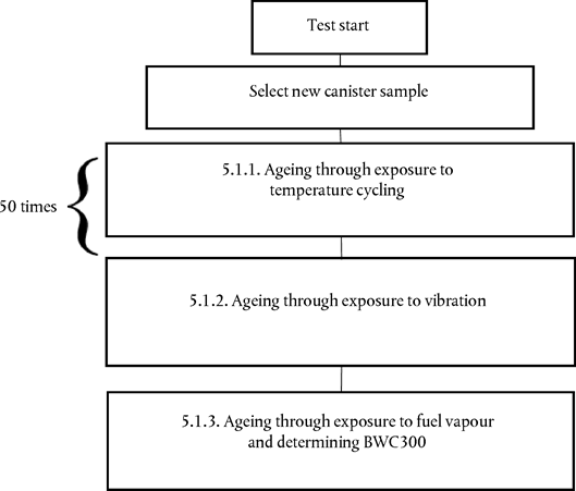
5.1.1.Ageing through exposure to temperature cycling
The canister shall be cycled between temperatures from – 15 °C to 60 °C in a dedicated temperature enclosure with 30 minutes of stabilisation at – 15 °C and 60 °C. Each cycle shall last 210 minutes (see Figure VI.2).
The temperature gradient shall be as close as possible to 1 °C/min. No forced air flow should pass through the canister.
The cycle shall be repeated 50 times consecutively. In total, this procedure lasts 175 hours.
Figure VI.2 Temperature conditioning cycle

5.1.2.Ageing through exposure to vibration
Following the temperature ageing procedure, the canister shall be shaken vertically with the canister mounted as per its orientation in the vehicle with an overall Grms > 1,5 m/sec2 with a frequency of 30 ± 10 Hz. The test shall last 12 hours.
5.1.3.Ageing through exposure to fuel vapour and determining BWC300
5.1.3.1.Ageing shall consist of repeatedly loading with fuel vapour and purging with laboratory air.
5.1.3.1.1.After temperature and vibration ageing, the canister shall be further aged with a mixture of market fuel as specified in paragraph 5.1.3.1.1.1. of this Appendix and nitrogen or air with a 50 ± 15 per cent fuel vapour volume. The fuel vapour fill rate shall be 60 ± 20 g/h.
The canister shall be loaded to 2 gram breakthrough. As an alternative, loading shall be deemed to be completed when the hydrocarbon concentration level at the vent outlet reaches 3 000 ppm.
5.1.3.1.1.1.The market fuel used for this test shall fulfil the same requirements as a reference fuel with respect to:
(a)
Density at 15 °C;
(b)
Vapour pressure;
(c)
Distillation (70 °C, 100 °C, 150 °C);
(d)
Hydrocarbon analysis (olefins, aromatics, benzene only);
(e)
Oxygen content;
(f)
Ethanol content.
5.1.3.1.2.The canister shall be purged between 5 and 60 minutes after loading with 25 ± 5 litres per minute of emission laboratory air until 300 bed volume exchanges are reached.
5.1.3.1.3.The procedures set out in paragraphs 5.1.3.1.1. and 5.1.3.1.2. of this Appendix shall be repeated 300 times after which the canister shall be considered to be stabilised.
5.1.3.1.4.The procedure to measure the butane working capacity (BWC) with respect to the evaporative emission family in paragraph 5.5. shall consist of the following.
(a)
The stabilised canister shall be loaded to 2 gram breakthrough and subsequently purged a minimum of 5 times. Loading shall be performed with a mixture composed of 50 per cent butane and 50 per cent nitrogen by volume at a rate of 40 grams butane per hour.
(b)
Purging shall be performed in accordance with paragraph 5.1.3.1.2. of this Appendix.
(c)
The BWC shall be included in all relevant test reports after each loading.
(d)
BWC300 shall be calculated as the average of the last 5 BWCs.
5.1.3.2.If an aged canister is provided by a supplier, the manufacturer shall inform the approval authority in advance of the ageing process to enable the witnessing of any part of that process in the supplier's facilities.
5.1.3.3.The manufacturer shall provide the approval authority a test report including at least the following elements:
(a)
Type of activated carbon;
(b)
Loading rate;
(c)
Fuel specifications.
5.2.Determination of the PF of the fuel tank system (see Figure VI.3)
Figure VI.3 Determination of the PF

5.2.1.The fuel tank system representative of a family shall be selected and mounted on a rig in a similar orientation as in the vehicle. The tank shall be filled to 40 ± 2 per cent of its nominal capacity with reference fuel at a temperature of 18 °C ± 2 °C. The rig with the fuel tank system shall be placed in a room with a controlled temperature of 40 °C ± 2 °C for 3 weeks.
5.2.2.At the end of the third week, the tank shall be drained and refilled with reference fuel at a temperature of 18 °C ± 2 °C to 40 ± 2 per cent of its nominal tank capacity.
Within 6 to 36 hours, the rig with the fuel tank system shall be placed in an enclosure. The last 6 hours of this period shall be at an ambient temperature of 20 °C ± 2 °C. In the enclosure, a diurnal procedure shall be performed over the first 24-hour period of the procedure described in paragraph 6.5.9. of this Appendix. The fuel vapour in the tank shall be vented to the outside of the enclosure to eliminate the possibility of the tank venting emissions being counted as permeation. The HC emissions shall be measured and the value shall be included in all relevant test reports as HC3W.
5.2.3.The rig with the fuel tank system shall be placed again in a room with a controlled temperature of 40 °C ± 2 °C for the remaining 17 weeks.
5.2.4.At the end of the seventeenth week, the tank shall be drained and refilled with reference fuel at a temperature of 18 °C ± 2 °C to 40 ± 2 per cent of its nominal tank capacity.
Within 6 to 36 hours, the rig with the fuel tank system shall be placed in an enclosure. The last 6 hours of this period shall be at an ambient temperature of 20 °C ± 2 °C. In the enclosure, a diurnal procedure shall be performed over a first period of 24 hours of the procedure described in accordance with paragraph 6.5.9. of this Appendix. The fuel tank system shall be vented to the outside of the enclosure to eliminate the possibility of the tank venting emissions being counted as permeation. The HC emissions shall be measured and the value shall be included in all relevant test reports in this case as HC20W.
5.2.5.The PF is the difference between HC20W and HC3W in g/24h calculated to 3 significant digits using the following equation:
PF = HC20w – HC3W
5.2.6.If the PF is determined by a supplier, the vehicle manufacturer shall inform the approval authority in advance of the determination to allow witness check in the supplier's facility.
5.2.7.The manufacturer shall provide the approval authority with a test report containing at least the following:
(a)
A full description of the fuel tank system tested, including information on the type of tank tested, whether the tank is metal, monolayer non-metal or multilayer, and which types of materials are used for the tank and other parts of the fuel tank system;
(b)
The weekly mean temperatures at which the ageing was performed;
(c)
The HC measured at week 3 (HC3W);
(d)
The HC measured at week 20 (HC20W);
(e)
The resulting permeability factor (PF).
5.2.8.As an alternative to paragraphs 5.2.1. to 5.2.7. of this Appendix, a manufacturer using multilayer tanks or metal tanks may choose to use an Assigned Permeability Factor (APF) instead of performing the complete measurement procedure mentioned above:
APF multilayer/metal tank = 120 mg /24 h
Where the manufacturer chooses to use an APF, the manufacturer shall provide the approval authority with a declaration in which the type of tank is clearly specified as well as a declaration of the type of materials used.
6. Test procedure for the measurement of hot soak and diurnal losses
6.1.Vehicle preparation
The vehicle shall be prepared in accordance to paragraphs 5.1.1. and 5.1.2. of Annex 7 of UN/ECE Regulation No 83. At the request of the manufacturer and with approval of the approval authority, non-fuel background emission sources (e.g. paint, adhesives, plastics, fuel/vapour lines, tyres, and other rubber or polymer components) may be reduced to typical vehicle background levels before testing (e.g. baking of tyres at temperatures of 50 °C or higher for appropriate periods, baking of the vehicle, draining washer fluid).
For a sealed fuel tank system, the vehicle canisters shall be installed so that access to canisters and connection/disconnection of canisters can be done easily.
6.2.Mode selections and gear shift prescriptions
6.2.1.For vehicles with manual shift transmissions, the gear shift prescriptions specified in Sub-Annex 2 of Annex XXI shall apply.
6.2.2.In the case of pure ICE vehicles, the mode shall be selected in accordance with Sub-Annex 6 of Annex XXI.
6.2.3.In the case of NOVC-HEVs and OVC-HEVs, the mode shall be selected in accordance with Appendix 6 to Sub-Annex 8 of Annex XXI.
6.2.4.Upon request of the approval authority, the selected mode may be different from that described in paragraphs 6.2.2. and 6.2.3. of this Appendix.
6.3.Test conditions
The tests included in this Annex shall be performed using the test conditions specific to interpolation family vehicle H with the highest cycle energy demand of all the interpolation families included in the evaporative emission family being considered.
Alternatively, at the request of the approval authority, any cycle energy representative of a vehicle in the family may be used for the test.
6.4.Flow of the test procedure
The test procedure for non-sealed and sealed tank systems shall be followed in accordance with the flow chart described in Figure VI.4.
The sealed fuel tank systems shall be tested with one of 2 options. One option is to test the vehicle with one continuous procedure. Another option, called the stand-alone procedure, is to test the vehicle with two separate procedures which will allow repeating the dynamometer test and the diurnal tests without repeating the tank depressurisation puff loss overflow test and the depressurisation puff loss measurement.
Figure VI.4 Test procedure flow charts

6.5.Continuous test procedure for non-sealed fuel tank systems
6.5.1.Fuel drain and refill
The fuel tank of the vehicle shall be emptied. This shall be done so as not to abnormally purge or abnormally load the evaporative control devices fitted to the vehicle. Removal of the fuel cap is normally sufficient to achieve this. The fuel tank shall be refilled with reference fuel at a temperature of 18 °C ± 2 °C to 40 ± 2 per cent of its nominal capacity.
6.5.2.Soak
Within 5 minutes after completing fuel drain and refill, the vehicle shall be soaked for a minimum of 6 hours and a maximum of 36 hours at 23 °C ± 3 °C.
6.5.3.Preconditioning drive
The vehicle shall be placed on a chassis dynamometer and driven over the following phases of the cycle described in Sub-Annex 1 of Annex XXI:
(a)
For Class 1 vehicles: low, medium, low, low, medium, low
(b)
For Class 2 and 3 vehicles: low, medium, high, medium.
For OVC-HEVs, the preconditioning drive shall be performed under the charge-sustaining operating condition as defined in paragraph 3.3.6. of Annex XXI. Upon the request of approval authority, any other mode may be used.
6.5.4.Fuel drain and refill
Within one hour after the preconditioning drive, the fuel tank of the vehicle shall be emptied. This shall be done so as not to abnormally purge or abnormally load the evaporative control devices fitted to the vehicle. Removal of the fuel cap is normally sufficient to achieve this. The fuel tank shall be refilled with test fuel at a temperature of 18 °C ± 2 °C to 40 ± 2 per cent of its nominal capacity.
6.5.5.Soak
Within five minutes of completing fuel drain and refill, the vehicle shall be parked for a minimum of 12 hours and a maximum of 36 hours at 23 °C ± 3 °C.
During soaking, the procedures described in paragraphs 6.5.5.1. and 6.5.5.2. may be performed either in the order of first paragraph 6.5.5.1. followed by paragraph 6.5.5.2. or in the order paragraph 6.5.5.2. followed by paragraph 6.5.5.1. The procedures described in paragraphs 6.5.5.1. and 6.5.5.2. may also be performed simultaneously.
6.5.5.1.REESS charge
For OVC-HEVs, the REESS shall be fully charged in accordance with the charging requirements described in paragraph 2.2.3. of Appendix 4 to Sub-Annex 8 of Annex XXI.
6.5.5.2.Canister loading
The canister aged in accordance with the sequence described in paragraph 5.1. of this Appendix shall be loaded to 2 gram breakthrough in accordance with the procedure described in paragraph 5.1.4. of Annex 7 of UN/ECE Regulation No 83.
6.5.6.Dynamometer test
The test vehicle shall be pushed onto a dynamometer and shall be driven over the cycles described in paragraph 6.5.3.(a) or paragraph 6.5.3.(b) of this Appendix. OVC-HEVs shall be operated in charge-depleting operating condition. The engine shall be subsequently shut off. Exhaust emissions may be sampled during this operation and the results may be used for the purpose of exhaust emission and fuel consumption type approval if this operation meets the requirement described in Sub-Annex 6 or Sub-Annex 8 of Annex XXI.
6.5.7.Hot soak evaporative emissions test
Within 7 minutes after the dynamometer test and within 2 minutes of the engine being switched off, the hot soak evaporative emissions test shall be performed in accordance with paragraph 5.5. of Annex 7 of UN/ECE Regulation No 83. The hot soak losses shall be calculated in accordance with paragraph 7.1. of this Appendix and included in all relevant test reports as MHS.
6.5.8.Soak
After the hot soak evaporative emissions test, the test vehicle shall be soaked for not less than 6 hours and not more than 36 hours between the end of the hot soak test and the start of the diurnal emission test. For at least the last 6 hours of this period the vehicle shall be soaked at 20 °C ± 2 °C.
6.5.9.Diurnal testing
6.5.9.1.The test vehicle shall be exposed to two cycles of ambient temperature pursuant to the profile specified for the diurnal emission test in Appendix 2 to Annex 7 of UN/ECE Regulation No 83 with a maximum deviation of ± 2 °C at any time. The average temperature deviation from the profile, calculated using the absolute value of each measured deviation, shall not exceed ± 1 °C. Ambient temperature shall be measured at least every minute and included in all relevant test sheets. Temperature cycling shall begin at time Tstart = 0, as specified in paragraph 6.5.9.6. of this Appendix.
6.5.9.2.The enclosure shall be purged for several minutes immediately before the test until a stable background is obtained. The chamber mixing fan(s) shall also be switched on at this time.
6.5.9.3.The test vehicle, with the powertrain shut off and the test vehicle windows and luggage compartment(s) opened, shall be moved into the measuring chamber. The mixing fan(s) shall be adjusted in such a way as to maintain a minimum air circulation speed of 8 km/h under the fuel tank of the test vehicle.
6.5.9.4.The hydrocarbon analyser shall be zeroed and spanned immediately before the test.
6.5.9.5.The enclosure doors shall be closed and sealed gas-tight.
6.5.9.6.Within 10 minutes of closing and sealing the doors, the hydrocarbon concentration, temperature and barometric pressure shall be measured to give initial readings of hydrocarbon concentration in the enclosure CHCi, barometric pressure Pi and ambient chamber temperature Ti for the diurnal testing. Tstart = 0 starts at this time.
6.5.9.7.The hydrocarbon analyser shall be zeroed and spanned immediately before the end of each emission sampling period.
6.5.9.8.The end of the first and second emission sampling period shall occur at 24 hours ±6 minutes and 48 hours ± 6 minutes, respectively, after the beginning of the initial sampling, as specified in paragraph 6.5.9.6. of this Appendix. The elapsed time shall be included in all relevant test reports.
At the end of each emission sampling period, the hydrocarbon concentration, temperature and barometric pressure shall be measured and used to calculate the diurnal test results using the equation in paragraph 7.1. of this Appendix. The result obtained from the first 24 hours shall be included in all relevant test reports as MD1. The result obtained from the second 24 hours shall be included in all relevant test reports as MD2.
6.6.Continuous test procedure for sealed fuel tank systems
6.6.1.In the case that the fuel tank relief pressure is greater than or equal to 30 kPa.
6.6.1.1.The test shall be performed as described in paragraphs 6.5.1. to 6.5.3. of this Appendix.
6.6.1.2.Fuel drain and refill
Within one hour after the preconditioning drive, the fuel tank of the vehicle shall be emptied. This shall be done so as not to abnormally purge or abnormally load the evaporative control devices fitted to the vehicle. Removal of the fuel cap is normally sufficient to achieve this, otherwise the canister shall be disconnected. The fuel tank shall be refilled with reference fuel at a temperature of 18 °C ± 2 °C to 15 ± 2 per cent of the tank's nominal capacity.
6.6.1.3.Soak
Within 5 minutes after completing fuel drain and refill, the vehicle shall be soaked for stabilization for 6 to 36 hours at an ambient temperature of 20 °C ± 2 °C.
6.6.1.4.Fuel tank depressurisation
The tank pressure shall be subsequently released so as not to abnormally raise the inside pressure of the fuel tank. This may be done by opening the fuel cap of the vehicle. Regardless of the method of depressurisation, the vehicle shall be returned to its original condition within 1 minute.
6.6.1.5.Canister loading and purge
The canister aged in accordance with the sequence described in paragraph 5.1. of this Appendix shall be loaded to 2 gram breakthrough in accordance with the procedure described in paragraph 5.1.6. of Annex 7 of UN/ECE Regulation No 83, and shall be subsequently purged with 25 ± 5 litres per minute with emission laboratory air. The volume of purge air shall not exceed the volume determined in paragraph 6.6.1.5.1. This loading and purging can be done either (a) using an on-board canister at a temperature of 20 °C or optionally 23 °C, or (b) by disconnecting the canister. In both cases, no further relief of the tank pressure is allowed.
6.6.1.5.1.Determination of maximum purge volume
The maximum purge amount Volmax shall be determined by the following equation. In the case of OVC-HEVs, the vehicle shall be operated in charge-sustaining operating condition. This determination can also be done at a separate test or during the preconditioning drive.

where:
VolPcycle
is the cumulative purge volume rounded to the nearest 0,1 litres measured using a suitable device (e.g. flowmeter connected to the vent of the carbon canister or equivalent) over the cold start preconditioning drive described in the paragraph 6.5.3. of this Appendix, l;
Voltank
is the manufacturer's nominal fuel tank capacity, l;
FCPcycle
is the fuel consumption over the single purge cycle described in paragraph 6.5.3. of this Appendix which may be measured in either warm or cold start condition, l/100 km. For OVC-HEVs and NOVC-HEVs, fuel consumption shall be calculated in accordance with paragraph 4.2.1. of Sub-Annex 8 of Annex XXI;
DistPcycle
is the theoretical distance to the nearest 0,1 km of a single purge cycle described in paragraph 6.5.3. of this Appendix, km.
6.6.1.6.Preparation of canister depressurisation puff loss loading
After completing canister loading and purging, the test vehicle shall be moved into an enclosure, either a SHED or an appropriate climatic chamber. It shall be demonstrated that the system is leak-free and the pressurisation is performed in a normal way during the test or by separate test (e.g. by means of pressure sensor on the vehicle). The test vehicle shall be subsequently exposed to the first 11 hours of the ambient temperature profile specified for the diurnal emission test in Appendix 2 to Annex 7 of UN/ECE Regulation No 83 with a maximum deviation of ± 2 °C at any time. The average temperature deviation from the profile, calculated using the absolute value of each measured deviation, shall not exceed ± 1 °C. The ambient temperature shall be measured at least every 10 minutes and included in all relevant test sheets.
6.6.1.7.Canister puff loss loading
6.6.1.7.1.Fuel tank depressurisation before refuelling
The manufacturer shall ensure that the refuelling operation cannot be initiated before the sealed fuel tank system is fully depressurised to a pressure less than 2,5 kPa above ambient pressure in normal vehicle operation and use. At the request of the approval authority, the manufacturer shall provide detailed information or demonstrate proof of operation (e.g. by means of pressure sensor on the vehicle). Any other technical solution may be allowed provided that a safe refuelling operation is ensured and that no excessive emissions are released to the atmosphere before the refuelling device is connected to the vehicle.
6.6.1.7.2.Within 15 minutes after the ambient temperature has reached 35 °C, the tank relief valve shall be opened to load the canister. This loading procedure may be executed either inside or outside an enclosure. The canister loaded in accordance with this paragraph shall be disconnected and shall be kept in the soak area. A dummy canister shall be installed to the vehicle when undertaking the procedure specified in paragraphs 6.6.1.9. to 6.6.1.12. of this Appendix.
6.6.1.8.Measurement of depressurisation puff loss overflow
6.6.1.8.1.Any depressurisation puff loss overflow from the vehicle canister shall be measured by using an auxiliary carbon canister connected directly at the outlet of the vehicle vapour storage unit. It shall be weighed before and after the procedure described in paragraph 6.6.1.7. of this Appendix.
6.6.1.8.2.Alternatively, the depressurisation puff loss overflow from the vehicle canister during its depressurisation may be measured using a SHED.
Within 15 minutes after the ambient temperature has reached 35 °C as described in paragraph 6.6.1.6. of this Appendix, the chamber shall be sealed and the measurement procedure shall be started.
The hydrocarbon analyser shall be zeroed and spanned, after which the hydrocarbon concentration, temperature and barometric pressure shall be measured to give the initial readings CHCi, Pi and Ti for the sealed tank depressurisation puff loss overflow determination.
The ambient temperature T of the enclosure shall not be less than 25 °C during the measurement procedure.
At the end of the procedure described in paragraph 6.6.1.7.2. of this Appendix, the hydrocarbon concentration in the chamber shall be measured after 60 ± 5 seconds. The temperature and the barometric pressure shall also be measured. These are the final readings CHCf, Pf and Tf for the sealed tank depressurisation puff loss overflow.
The sealed tank puff loss overflow result shall be calculated in accordance with paragraph 7.1. of this Appendix and included in all relevant test reports.
6.6.1.8.3.There shall be no change in weight of the auxiliary canister or the result of the SHED measurement, within the tolerance of ± 0,5 gram.
6.6.1.9.Soak
After completing puff loss loading, the vehicle shall be soaked at 23 ± 2 °C for 6 to 36 hours to stabilise the vehicle temperature.
6.6.1.9.1.REESS charge
For OVC-HEVs, the REESS shall be fully charged in accordance with the charging requirements described in paragraph 2.2.3. of Appendix 4 to Annex 8 of Annex XXI during the soaking described in paragraph 6.6.1.9. of this Appendix.
6.6.1.10.Fuel drain and refill
The fuel tank of the vehicle shall be drained and filled up to 40 ± 2 per cent of the tank's nominal capacity with reference fuel at a temperature of 18 °C ± 2 °C.
6.6.1.11.Soak
The vehicle shall be subsequently parked for a minimum of 6 hours to a maximum of 36 hours in the soak area at 20 °C ± 2 °C to stabilise the fuel temperature.
6.6.1.12.Fuel tank depressurisation
The tank pressure shall be subsequently released so as not to abnormally raise the inside pressure of the fuel tank. This may be done by opening the fuel cap of the vehicle. Regardless of the method of depressurisation, the vehicle shall be returned to its original condition within 1 minute. After this action, the vapour storage unit shall be connected again.
6.6.1.13.The procedures in paragraphs 6.5.6. to 6.5.9.8. of this Appendix shall be followed.
6.6.2.In the case that the fuel tank relief pressure is lower than 30 kPa
The test shall be performed as described in paragraphs 6.6.1.1. to 6.6.1.13. of this Appendix. However, in this case, the ambient temperature described in paragraph 6.5.9.1. of this Appendix shall be replaced by the profile specified in Table VI.1 of this Appendix for the diurnal emission test.
Table VI.1
Ambient temperature profile of the alternative sequence for sealed fuel tank system
| Time (hours) | Temperature (°C) |
|---|---|
| 0/24 | 20,0 |
| 1 | 20,4 |
| 2 | 20,8 |
| 3 | 21,7 |
| 4 | 23,9 |
| 5 | 26,1 |
| 6 | 28,5 |
| 7 | 31,4 |
| 8 | 33,8 |
| 9 | 35,6 |
| 10 | 37,1 |
| 11 | 38,0 |
| 12 | 37,7 |
| 13 | 36,4 |
| 14 | 34,2 |
| 15 | 31,9 |
| 16 | 29,9 |
| 17 | 28,2 |
| 18 | 26,2 |
| 19 | 24,7 |
| 20 | 23,5 |
| 21 | 22,3 |
| 22 | 21,0 |
| 23 | 20,2 |
6.7.Stand-alone test procedure for sealed fuel tank systems
6.7.1Measurement of depressurisation puff loss loading mass
6.7.1.1.The procedures in paragraphs 6.6.1.1. to 6.6.1.7.2. of this Appendix shall be performed. The depressurisation puff loss loading mass is defined as the difference in weight of the vehicle canister before paragraph 6.6.1.6. of this Appendix is applied and after paragraph 6.6.1.7.2. of this Appendix is applied.
6.7.1.2.The depressurisation puff loss overflow from the vehicle canister shall be measured in accordance with paragraphs 6.6.1.8.1. and 6.6.1.8.2. of this Appendix and fulfil the requirements of paragraph 6.6.1.8.3. in this Appendix.
6.7.2.Hot soak and diurnal breathing evaporative emissions test
6.7.2.1.In the case that the fuel tank relief pressure is greater than or equal to 30 kPa
6.7.2.1.1.The test shall be performed as described in paragraphs 6.5.1. to 6.5.3. and paragraphs 6.6.1.9. to 6.6.1.9.1. of this Appendix.
6.7.2.1.2.The canister shall be aged in accordance with the sequence described in paragraph 5.1. of this Appendix and shall be loaded and purged in accordance with paragraph 6.6.1.5. of this Appendix.
6.7.2.1.3.The aged canister shall subsequently be loaded in accordance with the procedure described in paragraph 5.1.6. of Annex 7 of UN/ECE Regulation No 83 with the exemption of loading mass. Total loading mass shall be determined in accordance with paragraph 6.7.1.1. of this Appendix. At the request of the manufacturer, the reference fuel may alternatively be used instead of butane. The canister shall be disconnected.
6.7.2.1.4.The procedures in paragraphs 6.6.1.10. to 6.6.1.13. of this Appendix shall be followed.
6.7.2.2.In the case that the fuel tank relief pressure is lower than 30 kPa
The test shall be performed as described in paragraphs 6.7.2.1.1. to 6.7.2.1.4. of this Appendix. However, in this case, the ambient temperature described in 6.5.9.1. of this Appendix shall be modified pursuant to the profile specified in Table VI.1 of this Appendix for the diurnal emission test.
7. Calculation of evaporative test results
7.1.The evaporative emission tests described in this Annex allow the hydrocarbon emissions from the puff loss overflow, diurnal and hot soak tests to be calculated. Evaporative losses from each of these tests shall be calculated using the initial and final hydrocarbon concentrations, temperatures and pressures in the enclosure, together with the net enclosure volume.
The following equation shall be used:

where:
MHC
is the mass of hydrocarbons, grams;
MHC,out
is the mass of hydrocarbons exiting the enclosure in the case of fixed volume enclosures for diurnal emission testing, grams;
MHC,in
is the mass of hydrocarbon entering the enclosure in the case of fixed volume enclosures for diurnal emission testing, grams;
CHC
is the measured hydrocarbon concentration in the enclosure, ppm volume in C1 equivalent;
V
is the net enclosure volume corrected for the volume of the vehicle with the windows and the luggage compartment open, m3. If the volume of the vehicle is not known, a volume of 1,42 m3 shall be subtracted;
T
is the ambient chamber temperature, K;
P
is the barometric pressure, kPa;
H/C
is the hydrogen to carbon ratio
where:
H/C
is taken to be 2,33 for puff loss overflow measurement in SHED and diurnal test losses;
H/C
is taken to be 2,20 for hot soak losses;
k
is 1,2 × 10– 4 × (12 + H/C), in (g × K/(m3 × kPa));
i
is the initial reading;
f
is the final reading;
7.2.The result of (MHS + MD1 + MD2 + (2 × PF)) shall be below the limit defined in paragraph 6.1.
8. Test report
The test report shall contain at least the following:
(a)
Description of the soak periods, including time and mean temperatures;
(b)
Description of aged canister used and reference to exact ageing report;
(c)
Mean temperature during the hot soak test;
(d)
Measurement during hot soak test, HSL;
(e)
Measurement of first diurnal, DL1st day;
(f)
Measurement of second diurnal, DL2nd day;
(g)
Final evaporative test result, calculated in accordance with paragraph 7. of this Appendix;
(h)
Declared fuel tank relief pressure of the system (for sealed tank systems);
(i)
Puff loss loading value (in the case of using the stand-alone test described in paragraph 6.7. of this Appendix).’
ANNEX VU.K.
Annex IX to Regulation (EU) 2017/1151 is amended as follows:
(1)
in Section A, point 3. is replaced by the following:
‘3.Technical data on fuels for testing fuel cell vehicles
Type: Hydrogen for fuel cell vehicles
| a The hydrogen fuel index is determined by subtracting the “total non-hydrogen gases” in this table, expressed in mole per cent, from 100 mole per cent. | ||||
| b Total hydrocarbons include oxygenated organic species. Total hydrocarbons shall be measured on a carbon basis (μmolC/mol). Total hydrocarbons may exceed 2 μmol/mol due only to the presence of methane, in which case the summation of methane, nitrogen and argon shall not exceed 100 μmol/mol. | ||||
| c As a minimum, total sulphur compounds include H2S, COS, CS2 and mercaptans, which are typically found in natural gas. | ||||
| d Total halogenated compounds include, for example, hydrogen bromide (HBr), hydrogen chloride (HCl), chlorine (Cl2), and organic halides (R-X). | ||||
| e Test method shall be documented. | ||||
| For the constituents that are additive, such as total hydrocarbons and total sulfur compounds, the sum of the constituents are to be less than or equal to the acceptable limit.’ | ||||
| Characteristics | Units | Limits | Test Method | |
|---|---|---|---|---|
| minimum | maximum | |||
| Hydrogen fuel indexa | % mole | 99,97 | ||
| Total non-hydrogen gases | μmol/mol | 300 | ||
| Maximum concentration of individual contaminants | ||||
| Water (H2O) | μmol/mol | 5 | e | |
| Total hydrocarbonsb (Methane basis) | μmol/mol | 2 | e | |
| Oxygen (O2) | μmol/mol | 5 | e | |
| Helium (He) | μmol/mol | 300 | e | |
| Total Nitrogen (N2) and Argon (Ar)b | μmol/mol | 100 | e | |
| Carbon dioxide (CO2) | μmol/mol | 2 | e | |
| Carbon monoxide (CO) | μmol/mol | 0,2 | e | |
| Total sulfur compoundsc (H2S basis) | μmol/mol | 0,004 | e | |
| Formaldehyde (HCHO) | μmol/mol | 0,01 | e | |
| Formic acid (HCOOH) | μmol/mol | 0,2 | e | |
| Ammonia (NH3) | μmol/mol | 0,1 | e | |
| Total halogenated compoundsd (Halogenate ion basis) | μmol/mol | 0,05 | e | |
ANNEX VIU.K.
‘ANNEX XIU.K. ON-BOARD DIAGNOSTICS (OBD) FOR MOTOR VEHICLES
1.INTRODUCTION
1.1.This Annex sets out the functional aspects of on-board diagnostic (OBD) systems for the control of emissions from motor vehicles.
2.DEFINITIONS, REQUIREMENTS AND TESTS
2.1.The definitions, requirements and tests for OBD systems set out in Sections 2 and 3 of Annex 11 to UN/ECE Regulation No 83 shall apply for the purposes of this Annex, with the exceptions set out in this Annex.
2.1.1.The introductory text to paragraph 2. of Annex 11 to UN/ECE Regulation No 83 shall be understood as follows:
‘For the purposes of this Annex only:’
2.1.2.Paragraph 2.10. of Annex 11 to UN/ECE Regulation No 83 shall be understood as follows:
‘A “driving cycle” consists of engine key on, a driving mode where a malfunction would be detected if present, and engine key-off’
2.1.3.In addition to the requirements of paragraph 3.2.2. of Annex 11 of UN/ECE Regulation No 83, identification of deterioration or malfunctions may be also be done outside a driving cycle (e.g. after engine shutdown).
2.1.4.Paragraph 3.3.3.1. of Annex 11 of UN/ECE Regulation No 83 shall be understood as follows:
‘3.3.3.1.The reduction in the efficiency of the catalytic converter with respect to emissions of NMHC and NOx. Manufacturers may monitor the front catalyst alone or in combination with the next catalyst(s) downstream. Each monitored catalyst or catalyst combination shall be considered malfunctioning when the emissions exceed the NMHC or NOx threshold limits provided for by paragraph 3.3.2. of this Annex.’
2.1.5.The reference to ‘the threshold limits’ in Section 3.3.3.1 of Annex 11 to UNECE Regulation No 83 shall be understood as reference to the threshold limits in Section 2.3 of this Annex..
2.1.6.Reserved.
2.1.7.Paragraphs 3.3.4.9. and 3.3.4.10. of Annex 11 of UN/ECE Regulation No 83 shall not apply.
2.1.8.Paragraphs 3.3.5. to 3.3.5.2. of Annex 11 of UN/ECE Regulation No 83 shall be understood as follows:
‘3.3.5.Manufacturers may demonstrate to the Type Approval Authority that certain components or systems need not be monitored if, in the event of their total failure or removal, emissions do not exceed the OBD threshold limits given in paragraph 3.3.2. of this Annex.
3.3.5.1.The following devices should however be monitored for total failure or removal (if removal would cause the applicable emission limits in paragraph 5.3.1.4. of this Regulation to be exceeded):
(a)
A particulate trap fitted to compression ignition engines as a separate unit or integrated into a combined emission control device;
(b)
A NOx after treatment system fitted to compression ignition engines as a separate unit or integrated into a combined emission control device;
(c)
A Diesel Oxidation Catalyst (DOC) fitted to compression ignition engines as a separate unit or integrated into a combined emission control device.
3.3.5.2.The devices referred to in paragraph 3.3.5.1. of this Annex shall also be monitored for any failure that would result in exceeding the applicable OBD threshold limits.’
2.1.9.Paragraph 3.8.1. of Annex 11 to UN/ECE Regulation No 83 shall be understood as follows:
‘The OBD system may erase a fault code and the distance travelled and freeze-frame information if the same fault is not re-registered in at least 40 engine warm-up cycles or 40 driving cycles with vehicle operation in which the criteria specified in sections 7.5.1.(a)–(c) of Annex 11, Appendix 1 are met.’
2.1.10.The reference to ‘ISO DIS 15031 5’ in paragraph 3.9.3.1. of Annex 11 to UN/ECE Regulation No 83 shall be understood as follows:
“… the standard listed in paragraph 6.5.3.2.(a) of Annex 11, Appendix 1 of this Regulation.”
2.1.11.In addition to the requirements of paragraph 3. of Annex 11 of UN/ECE Regulation No 83 the following shall apply:
‘Additional provisions for vehicles employing engine shut - off strategiesDriving cycle
Autonomous engine restarts commanded by the engine control system following an engine stall may be considered a new driving cycle or a continuation of the existing driving cycle.’
2.2.The ‘Type V durability distance’ and ‘Type V durability test’ mentioned in section 3.1 and 3.3.1 of Annex 11 to UN/ECE Regulation No 83 respectively shall be understood as reference to the requirements of Annex VII to this Regulation.
2.3.The ‘OBD threshold limits’ specified in section 3.3.2 of Annex 11 to UN/ECE Regulation 83 shall be understood as reference to the requirements specified in points 2.3.1. and 2.3.2. below:
2.3.1.
The OBD thresholds limits for vehicles that are type approved in accordance with the Euro 6 emission limits set out in Table 2 of Annex I to Regulation (EC) No 715/2007 from three years after the dates given in Article 10(4) and 10(5) of that Regulation are given in the following table:
| a Positive ignition particulate mass and particle number limits apply only to vehicles with direct injection engines. | ||||||||||||
| b Particle number limits may be introduced at a later date. | ||||||||||||
| Key: PI = Positive Ignition, CI = Compression Ignition. | ||||||||||||
| Final Euro 6 OBD threshold limits | ||||||||||||
|---|---|---|---|---|---|---|---|---|---|---|---|---|
| Reference mass(RM) (kg) | Mass of carbon monoxide | Mass of non-methane hydrocarbons | Mass of oxides of nitrogen | Mass of particulate mattera | Number of particlesb | |||||||
| Category | Class | (CO)(mg/km) | (NMHC)(mg/km) | (NOx)(mg/km) | (PM)(mg/km) | (PN)(#/km) | ||||||
| PI | CI | PI | CI | PI | CI | CI | PI | CI | PI | |||
| M | — | All | 1 900 | 1 750 | 170 | 290 | 90 | 140 | 12 | 12 | ||
| N1 | I | RM ≤ 1 305 | 1 900 | 1 750 | 170 | 290 | 90 | 140 | 12 | 12 | ||
| II | 1 305 < RM ≤ 1 760 | 3 400 | 2 200 | 225 | 320 | 110 | 180 | 12 | 12 | |||
| III | 1 760 < RM | 4 300 | 2 500 | 270 | 350 | 120 | 220 | 12 | 12 | |||
| N2 | — | All | 4 300 | 2 500 | 270 | 350 | 120 | 220 | 12 | 12 | ||
2.3.2.
Until three years after the dates specified in Article 10(4) and (5) of Regulation (EC) No 715/2007 for new type approvals and new vehicles respectively, the following OBD threshold limits shall be applied to vehicles that are type approved in accordance with the Euro 6 emission limits set out in Table 2 of Annex I to Regulation (EC) No 715/2007, upon the choice of the manufacturer:
| a Positive ignition particulate mass limits apply only to vehicles with direct injection engines. | ||||||||||
| Key: PI = Positive Ignition, CI = Compression Ignition | ||||||||||
| Preliminary Euro 6 OBD threshold limits | ||||||||||
|---|---|---|---|---|---|---|---|---|---|---|
| Reference mass(RM) (kg) | Mass of carbon monoxide | Mass of non-methane hydrocarbons | Mass of oxides of nitrogen | Mass of particulate mattera | ||||||
| Category | Class | (CO)(mg/km) | (NMHC)(mg/km) | (NOx)(mg/km) | (PM)(mg/km) | |||||
| PI | CI | PI | CI | PI | CI | CI | PI | |||
| M | — | All | 1 900 | 1 750 | 170 | 290 | 150 | 180 | 25 | 25 |
| N1 | I | RM ≤ 1 305 | 1 900 | 1 750 | 170 | 290 | 150 | 180 | 25 | 25 |
| II | 1 305 < RM ≤ 1 760 | 3 400 | 2 200 | 225 | 320 | 190 | 220 | 25 | 25 | |
| III | 1 760 < RM | 4 300 | 2 500 | 270 | 350 | 210 | 280 | 30 | 30 | |
| N2 | — | All | 4 300 | 2 500 | 270 | 350 | 210 | 280 | 30 | 30 |
2.4.
2.5.Reserved.
2.6.The ‘Type I test cycle’ referred to in paragraph 3.3.3.2. of Annex 11 to UN/ECE Regulation No 83 shall be understood as being the same as the Type 1 cycle that was used for at least two consecutive cycles after introduction of the misfire faults in accordance with paragraph 6.3.1.2. of Appendix 1 to Annex 11 to UN/ECE Regulation No 83.
2.7.The reference to ‘the particulate threshold limits provided for by paragraph 3.3.2.’ in paragraph 3.3.3.7. of Annex 11 to UN/ECE Regulation No 83 shall be understood as being reference to the particulate threshold limits provided in Section 2.3 of this Annex.
2.8.Paragraph 3.3.3.4. of Annex 11 of UN/ECE Regulation No 83 shall be understood as follows:
‘3.3.3.4.If active on the selected fuel, other emission control system components or systems, or emission related power train components or systems which are connected to a computer, the failure of which may result in tailpipe emissions exceeding the OBD threshold limits given in paragraph 3.3.2. of this Annex.’
2.9.Paragraph 3.3.4.4. of Annex 11 of UN/ECE Regulation No 83 shall be understood as follows:
‘3.3.4.4.Other emission control system components or systems, or emission-related power-train components or systems, which are connected to a computer, the failure of which may result in exhaust emissions exceeding the OBD threshold limits given in paragraph 3.3.2. of this Annex. Examples of such systems or components are those for monitoring and control of air mass-flow, air volumetric flow (and temperature), boost pressure and inlet manifold pressure (and relevant sensors to enable these functions to be carried out).’
3.ADMINISTRATIVE PROVISIONS FOR DEFICIENCIES OF OBD SYSTEMS
3.1.The administrative provisions for deficiencies of OBD systems as set out in Article 6(2) shall be those specified in Section 4 of Annex 11 of UN/ECE Regulation No 83 with the following exceptions.
3.2.Reference to ‘OBD threshold limits’ in paragraph 4.2.2. of Annex 11 to UN/ECE Regulation No 83 shall be understood as being reference to the OBD threshold limits in Section 2.3 of this Annex.
3.3.Paragraph 4.6 of Annex 11 to UN/ECE Regulation No 83 shall be understood as being as follows:
‘The approval authority shall notify its decision in granting a deficiency request in accordance with Article 6(2).’
4.ACCESS TO OBD INFORMATION
4.1.Requirements for access to OBD information are specified in section 5 of Annex 11 to UN/ECE Regulation 83. The exceptions to these requirements are described in the following sections.
4.2.References to Appendix 1 of Annex 2 to UN/ECE Regulation No 83 shall be understood as references to Appendix 5 to Annex I to this Regulation.
4.3.References to section 3.2.12.2.7.6. of Annex 1 to UN/ECE Regulation No 83 shall be understood as references to 3.2.12.2.7.6 of Appendix 3 to Annex I to this Regulation.
4.4.References to ‘contracting parties’ shall be understood as references to ‘member states’.
4.5.References to ‘approval granted under Regulation 83’ shall be understood as references to type-approval granted under this Regulation and Regulation (EC) No 715/2007.
4.6.UN/ECE type-approval shall be understood as EC type-approval.
Appendix 1U.K. FUNCTIONAL ASPECTS OF ON-BOARD DIAGNOSTIC (OBD) SYSTEMS
1.INTRODUCTION
1.1.This Appendix describes the procedure of the test in accordance with section 2 of this Annex.
2.TECHNICAL REQUIREMENTS
2.1.The technical requirements and specifications shall be those set out in Appendix 1 to Annex 11 to UN/ECE Regulation No 83 with the exceptions and additional requirements as described in the following sections.
2.2.The references in Appendix 1 to Annex 11 to UN/ECE Regulation No 83 to the OBD threshold limits set out in paragraph 3.3.2. to Annex 11 of UN/ECE Regulation No 83 shall be understood as references to the OBD threshold limits set out in section 2.3 of this Annex.
2.3.The reference to ‘the Type I test cycle’ in section 2.1.3 of Appendix 1 to Annex 11 of UN/ECE Regulation No 83 shall be understood as a reference to the Type 1 test in accordance with Regulation (EC) No 692/2008 or Annex XXI of this Regulation, upon the choice of the manufacturer for each individual malfunction to be demonstrated.
2.4.The reference fuels specified in paragraph 3.2. of Appendix 1 of Annex 11 of UN/ECE Regulation No 83 shall be understood as reference to the appropriate reference fuel specifications in Annex IX to this Regulation.
2.5.Paragraph 6.4.1.1. of Appendix 1 to Annex 11 of UN/ECE Regulation No 83 shall be understood as follows:
‘6.4.1.1.After vehicle preconditioning in accordance with paragraph 6.2. of this Appendix, the test vehicle is driven over a Type I test (Parts One and Two).
The MI shall be activated at the latest before the end of this test under any of the conditions given in paragraphs 6.4.1.2. to 6.4.1.5. of this Appendix. The MI may also be activated during preconditioning. The Technical Service may substitute those conditions with others in accordance with paragraph 6.4.1.6. of this Appendix. However, the total number of failures simulated shall not exceed four (4) for the purpose of type approval.
In the case of testing a bi-fuel gas vehicle, both fuel types shall be used within the maximum of four (4) simulated failures at the discretion of the Type Approval Authority.’
2.6.The reference to “Annex 11” in paragraph 6.5.1.4. of Appendix 1 of Annex 11 of UN/ECE Regulation No 83 shall be understood as reference to Annex XI to this Regulation.
2.7.In addition to the requirements of the second paragraph of Section 1 of Appendix 1 to Annex 11 of UN/ECE Regulation No 83 the following shall apply:
‘For electrical failures (short/open circuit), the emissions may exceed the limits of paragraph 3.3.2. by more than twenty per cent.’
2.8.Paragraph 6.5.3. of Appendix 1 to Annex 11 of UN/ECE Regulation No 83 shall be understood as follows:
‘6.5.3.The emission control diagnostic system shall provide for standardised and unrestricted access and conform with the following ISO standards and/or SAE specification. Later versions may be used if any of the following standards have been withdrawn and replaced by the relevant standardisation organisation.
6.5.3.1.The following standard shall be used as the on board to off-board communications link:
(a)
ISO 15765-4:2011 “Road vehicles – Diagnostics on Controller Area Network (CAN) – Part 4: Requirements for emissions-related systems”, dated April 2016;
6.5.3.2.Standards used for the transmission of OBD relevant information:
(a)
ISO 15031-5 “Road vehicles - communication between vehicles and external test equipment for emissions-related diagnostics – Part 5: Emissions-related diagnostic services”, dated August 2015 or SAE J1979 dated February 2017;
(b)
ISO 15031-4 “Road vehicles – Communication between vehicle and external test equipment for emissions related diagnostics – Part 4: External test equipment”, dated February 2014 or SAE J1978 dated 30 April 2002;
(c)
ISO 15031-3 “Road vehicles – Communication between vehicle and external test equipment for emissions related diagnostics Part 3: Diagnostic connector and related electrical circuits: specification and use”, dated April 2016 or SAE J1962 dated 26 July 2012;
(d)
ISO 15031-6 “Road vehicles – Communication between vehicle and external test equipment for emissions related diagnostics – Part 6: Diagnostic trouble code definitions”, dated August 2015 or SAE J2012 dated 7 March 2013;
(e)
ISO 27145 “Road vehicles – Implementation of World-Wide Harmonized On-Board Diagnostics (WWH-OBD)” dated 2012-08-15 with the restriction, that only paragraph 6.5.3.1.(a) may be used as a data link;
(f)
ISO 14229:2013 “Road vehicles – Unified diagnostic services (UDS) with the restriction, that only 6.5.3.1.(a) may be used as a data link”.
The standards (e) and (f) may be used as an option instead of (a) not earlier than 1 January 2019.
6.5.3.3.Test equipment and diagnostic tools needed to communicate with OBD systems shall meet or exceed the functional specification given in the standard listed in paragraph 6.5.3.2.(b) of this Appendix.
6.5.3.4.Basic diagnostic data, (as specified in paragraph 6.5.1.) and bi-directional control information shall be provided using the format and units described in the standard listed in paragraph 6.5.3.2.(a) of this Appendix, and must be available using a diagnostic tool meeting the requirements of the standard listed in paragraph 6.5.3.2.(b) of this Appendix.
The vehicle manufacturer shall provide to a national standardisation body the details of any emission-related diagnostic data, e.g. PID's, OBD monitor Id's, Test Id's not specified in the standard listed in paragraph 6.5.3.2.(a) of this Regulation but related to this Regulation.
6.5.3.5.When a fault is registered, the manufacturer shall identify the fault using an appropriate ISO/SAE controlled fault code specified in one of the standards listed in paragraph 6.5.3.2.(d) of this Appendix, relating to “emission related system diagnostic trouble codes”. If such identification is not possible, the manufacturer may use manufacturer controlled diagnostic trouble codes in accordance with the same standard. The fault codes shall be fully accessible by standardised diagnostic equipment complying with the provisions of paragraph 6.5.3.3. of this Appendix.
The vehicle manufacturer shall provide to a national standardisation body the details of any emission-related diagnostic data, e.g. PID's, OBD monitor Id's, Test Id's not specified in the standards listed in paragraph 6.5.3.2.(a) of this Appendix but related to this Regulation.
6.5.3.6.The connection interface between the vehicle and the diagnostic tester shall be standardised and shall meet all the requirements of the standard listed in paragraph 6.5.3.2.(c) of this Appendix. The installation position shall be subject to agreement of the administrative department such that it is readily accessible by service personnel but protected from tampering by non-qualified personnel.
6.5.3.7.The manufacturer shall also make accessible, where appropriate on payment, the technical information required for the repair or maintenance of motor vehicles unless that information is covered by an intellectual property right or constitutes essential, secret know-how which is identified in an appropriate form; in such case, the necessary technical information shall not be withheld improperly.
Entitled to such information is any person engaged in commercially servicing or repairing, road-side rescuing, inspecting or testing of vehicles or in the manufacturing or selling replacement or retro-fit components, diagnostic tools and test equipment.’
2.9.In addition to the requirements of paragraph 6.1. of Appendix 1 to Annex 11 of UN/ECE Regulation No 83 the following shall apply:
‘The Type I Test need not be performed for the demonstration of electrical failures (short/open circuit). The manufacturer may demonstrate these failure modes using driving conditions in which the component is used and the monitoring conditions are encountered. These conditions shall be documented in the type approval documentation.’
2.10Paragraph 6.2.2. of Appendix 1 of Annex 11 of UN/ECE Regulation No 83 shall be understood as follows:
‘At the request of the manufacturer, alternative and/or additional preconditioning methods may be used.’
2.11In addition to the requirements of paragraph 6.2. of Appendix 1 to Annex 11 of UN/ECE Regulation No 83 the following shall apply:
‘The use of additional preconditioning cycles or alternative preconditioning methods shall be documented in the type approval documentation.’
2.12.Paragraph 6.3.1.5. of Appendix 1 to Annex 11 of UN/ECE Regulation No 83 shall be understood as follows:
‘Electrical disconnection of the electronic evaporative purge control device (if equipped and if active on the selected fuel type).’
2.13.Reserved.
2.14.Paragraph 6.4.2.1. of Appendix 1 to Annex 11 of UN/ECE Regulation No 83 shall be understood as follows:
‘After vehicle preconditioning in accordance with paragraph 6.2. of this Appendix, the test vehicle is driven over a Type I test (Parts One and Two).
The MI shall be activated at the latest before the end of this test under any of the conditions given in paragraphs 6.4.2.2. to 6.4.2.5. The MI may also be activated during preconditioning. The Technical Service may substitute those conditions by others in accordance with paragraph 6.4.2.5. of this appendix. However, the total number of failures simulated shall not exceed four (4) for the purposes of type approval.’
2.15.The information listed in point 3 of Annex XXII shall be made available as signals through the serial port connector referred to in paragraph 6.5.3.2 (c) of Appendix 1 to Annex 11 to UN/ECE Regulation No 83, understood as set out in point 2.8 of Appendix 1 to this Annex.
3.IN-USE PERFORMANCE
3.1. General Requirements
The technical requirements and specifications shall be those set out in Appendix 1 to Annex 11 to UN/ECE Regulation No 83 with the exceptions and additional requirements as described in the following sections.
3.1.1.The requirements of paragraph 7.1.5. of Appendix 1 to Annex 11 to UN/ECE Regulation No 83 shall be understood as being as follows.
For new type approvals and new vehicles the monitor required by paragraph 3.3.4.7. of Annex 11 to UN/ECE Regulation No 83 shall have an IUPR greater or equal to 0,1 until three years after the dates specified in Article 10(4) and (5) of Regulation (EC) No 715/2007 respectively.
3.1.2.The requirements of paragraph 7.1.7. of Appendix 1 to Annex 11 to UN/ECE Regulation No 83 shall be understood as being as follows.
The manufacturer shall demonstrate to the approval authority and, upon request, to the Commission that these statistical conditions are satisfied for all monitors required to be reported by the OBD system in accordance with paragraph 7.6. of Appendix 1 to Annex 11 to Regulation No 83 not later than 18 months after the entry onto the market of the first vehicle type with IUPR in an OBD family and every 18 months thereafter. For this purpose, for OBD families consisting of more than 1 000 registrations in the Union, that are subject to sampling within the sampling period, the process described in Annex II shall be used without prejudice to the provisions of paragraph 7.1.9. of Appendix 1 to Annex 11 to Regulation No 83.
In addition to the requirements set out in Annex II and regardless of the result of the audit described in Section 2 of Annex II, the authority granting the approval shall apply the in-service conformity check for IUPR described in Appendix 1 to Annex II in an appropriate number of randomly determined cases. ‘In an appropriate number of randomly determined cases’ means, that this measure has a dissuasive effect on non-compliance with the requirements of Section 3 of this Annex or the provision of manipulated, false or non-representative data for the audit. If no special circumstances apply and can be demonstrated by the type-approval authorities, random application of the in-service conformity check to 5 % of the type approved OBD families shall be considered as sufficient for compliance with this requirement. For this purpose, type-approval authorities may find arrangements with the manufacturer for the reduction of double testing of a given OBD family as long as these arrangements do not harm the dissuasive effect of the type-approval authority's own in-service conformity check on non-compliance with the requirements of Section 3 of this Annex. Data collected by Member States during surveillance testing programmes may be used for in-service conformity checks. Upon request, type-approval authorities shall provide data on the audits and random in-service conformity checks performed, including the methodology used for identifying those cases, which are made subject to the random in-service conformity check, to the Commission and other type-approval authorities.
3.1.3.Non-compliance with the requirements of paragraph 7.1.6. of Appendix 1 to Annex 11 to Regulation No 83 established by tests described in point 3.1.2 of this Appendix or paragraph 7.1.9 of Appendix 1 to Annex 11 to Regulation No 83 shall be considered as an infringement subject to the penalties set out in Article 13 of Regulation (EC) No 715/2007. This reference does not limit the application of such penalties to other infringements of other provisions of Regulation (EC) No 715/2007 or this Regulation, which do not explicitly refer to Article 13 of Regulation (EC) No 715/2007.
3.1.4.Paragraph 7.6.1. of Appendix 1 to Annex 11 of UN/ECE Regulation No 83 shall be replaced with the following:
‘7.6.1.The OBD system shall report, in accordance with the standard listed in paragraph 6.5.3.2.(a) of this Appendix, the ignition cycle counter and general denominator as well as separate numerators and denominators for the following monitors, if their presence on the vehicle is required by this Annex:
(a)
Catalysts (each bank to be reported separately);
(b)
Oxygen/exhaust gas sensors, including secondary oxygen sensors
(each sensor to be reported separately);
(c)
Evaporative system;
(d)
EGR system;
(e)
VVT system;
(f)
Secondary air system;
(g)
Particulate trap/filter;
(h)
NOx after-treatment system (e.g. NOx absorber, NOx reagent/catalyst system);
(i)
Boost pressure control system.’
3.1.5.Paragraph 7.6.2. of Appendix 1 to Annex 11 of UN/ECE Regulation No 83 shall be understood as follows:
‘7.6.2.For specific components or systems that have multiple monitors, which are required to be reported by this point (e.g. oxygen sensor bank 1 may have multiple monitors for sensor response or other sensor characteristics), the OBD system shall separately track numerators and denominators for each of the specific monitors and report only the corresponding numerator and denominator for the specific monitor that has the lowest numerical ratio. If two or more specific monitors have identical ratios, the corresponding numerator and denominator for the specific monitor that has the highest denominator shall be reported for the specific component.’
3.1.6.In addition to the requirements of paragraph 7.6.2. of Appendix 1 to Annex 11 of UN/ECE Regulation No 83 the following shall apply:
‘Numerators and denominators for specific monitors of components or systems, that are monitoring continuously for short circuit or open circuit failures are exempted from reporting.
“Continuously,” if used in this context means monitoring is always enabled and sampling of the signal used for monitoring occurs at a rate no less than two samples per second and the presence or the absence of the failure relevant to that monitor has to be concluded within 15 seconds.
If for control purposes, a computer input component is sampled less frequently, the signal of the component may instead be evaluated each time sampling occurs.
It is not required to activate an output component/system for the sole purpose of monitoring that output component/system.’
Appendix 2U.K. ESSENTIAL CHARACTERISTICS OF THE VEHICLE FAMILY
The essential characteristics of the vehicle family shall be those specified in Appendix 2 to Annex 11 to UN/ECE Regulation No 83.’
ANNEX VIIU.K.
Annex XII to Regulation (EU) 2017/1151 is amended as follows:
(1)
the heading is replaced by the following:
‘TYPE-APPROVAL OF VEHICLES FITTED WITH ECO-INNOVATIONS AND DETERMINATION OF CO2 EMISSIONS AND FUEL CONSUMPTION FROM VEHICLES SUBMITTED TO MULTI-STAGE TYPE-APPROVAL OR INDIVIDUAL VEHICLE APPROVAL’;
(2)
point 1.4. is deleted;
(3)
point 2 is replaced by the following:
‘2.DETERMINATION OF CO2 EMISSIONS AND FUEL CONSUMPTION FROM VEHICLES SUBMITTED TO MULTI-STAGE TYPE-APPROVAL OR INDIVIDUAL VEHICLE APPROVAL
2.1.For the purpose of determining the CO2 emissions and fuel consumption of a vehicle submitted to multi-stage type-approval, as defined in Article 3(7) of Directive 2007/46/EC, the procedures of Annex XXI apply. However, at the choice of the manufacturer and irrespective of the technically permissible maximum laden mass, the alternative described in paragraphs 2.2. to 2.6. may be used where the base vehicle is incomplete.
2.2.A road load matrix family, as defined in paragraph 5.8. of Annex XXI, shall be established based on the parameters of a representative multi-stage vehicle in accordance with paragraph 4.2.1.4. of Sub-Annex 4 to Annex XXI.
2.3.The manufacturer of the base vehicle shall calculate the road load coefficients of vehicle HM and LM of a road load matrix family as set out in paragraph 5. of Sub-Annex 4 to Annex XXI and shall determine the CO2 emission and fuel consumption in a Type 1 test of both vehicles. The manufacturer of the base vehicle shall make available a calculation tool to establish, on the basis of the parameters of completed vehicles, the final fuel consumption and CO2 values as specified in Sub-Annex 7 to Annex XXI.
2.4.The calculation of road load and running resistance for an individual multi stage vehicle shall be performed in accordance with paragraph 5.1. of Sub-Annex 4 of Annex XXI.
2.5.The final fuel consumption and CO2 values shall be calculated by the final-stage manufacturer on the basis of the parameters of the completed vehicle as specified in paragraph 3.2.4. of Sub-Annex 7 of Annex XXI and using the tool supplied by the manufacturer of the base vehicle.
2.6.The manufacturer of the completed vehicle shall include, in the certificate of conformity, the information of the completed vehicles and add the information of the base vehicles in accordance with Annex IX to Directive 2007/46/EC.
2.7.In the case of multi stage vehicles submitted to individual vehicle approval, the individual approval certificate shall include the following information:
(a)
the CO2 emissions measured in accordance with the methodology set out in points 2.1 to 2.6.;
(b)
the mass of the completed vehicle in running order;
(c)
the identification code corresponding to the type, variant and version of the base vehicle;
(d)
the type-approval number of the base vehicle, including the extension number;
(e)
the name and address of the manufacturer of the base vehicle;
(f)
the mass of the base vehicle in running order.
2.8.In the case of multi stage type approvals or individual vehicle approval where the base vehicle is a complete vehicle with a valid certificate of conformity, the final stage manufacturer shall consult the base vehicle manufacturer to set the new CO2 value in accordance with the CO2 interpolation using the appropriate data from the completed vehicle or calculate the new CO2 value on the basis of the parameters of the completed vehicle as specified in paragraph 3.2.4. of Sub-Annex 7 of Annex XXI and using the tool supplied by the manufacturer of the base vehicle as mentioned in paragraph 2.3. above. If the tool is not available or the CO2 interpolation is not possible, the CO2 value of Vehicle High from the base vehicle shall be used with the agreement of the approval authority.’;
ANNEX VIIIU.K.
‘ANNEX XVIU.K. REQUIREMENTS FOR VEHICLES THAT USE A REAGENT FOR THE EXHAUST AFTER-TREATMENT SYSTEM
1.Introduction
This Annex sets out the requirements for vehicles that rely on the use of a reagent for the after-treatment system in order to reduce emissions. Every reference in this Annex to ‘reagent tank’ shall be understood as also applying to other containers in which a reagent is stored.
1.1.The capacity of the reagent tank shall be such that a full reagent tank does not need to be replenished over an average driving range of 5 full fuel tanks providing the reagent tank can be easily replenished (e.g. without the use of tools and without removing vehicle interior trim. The opening of an interior flap, in order to gain access for the purpose of reagent replenishment, shall not be understood as the removal of interior trim). If the reagent tank is not considered to be easy to replenish as described above, the minimum reagent tank capacity shall be at least equivalent to an average driving distance of 15 full fuel tanks. However, in the case of the option in paragraph 3.5., where the manufacturer chooses to start the warning system at a distance which may not be less than 2 400 km before the reagent tank becomes empty, the above restrictions on a minimum reagent tank capacity shall not apply.
1.2.In the context of this Annex, the term “average driving distance” shall be taken to be derived from the fuel or reagent consumption during a Type 1 test for the driving distance of a fuel tank and the driving distance of a reagent tank respectively.
2.Reagent indication
2.1.The vehicle shall include a specific indicator on the dashboard that informs the driver when reagent levels are below the threshold values specified in paragraph 3.5.
3.Driver warning system
3.1.The vehicle shall include a warning system consisting of visual alarms that informs the driver when an abnormality is detected in the reagent dosing, e.g. when emissions are too high, the reagent level is low, reagent dosing is interrupted, or the reagent is not of a quality specified by the manufacturer. The warning system may also include an audible component to alert the driver.
3.2.The warning system shall escalate in intensity as the reagent approaches empty. It shall culminate in a driver notification that cannot be easily defeated or ignored. It shall not be possible to turn off the system until the reagent has been replenished.
3.3.The visual warning shall display a message indicating a low level of reagent. The warning shall not be the same as the warning used for the purposes of OBD or other engine maintenance. The warning shall be sufficiently clear for the driver to understand that the reagent level is low (e.g. “urea level low”, “AdBlue level low”, or “reagent low”).
3.4.The warning system does not initially need to be continuously activated, however the warning shall escalate so that it becomes continuous as the level of the reagent approaches the point where the driver inducement system in paragraph 8. comes into effect. An explicit warning shall be displayed (e.g. “fill up urea”, “fill up AdBlue”, or “fill up reagent”). The continuous warning system may be temporarily interrupted by other warning signals providing that they are important safety related messages.
3.5.The warning system shall activate at a distance equivalent to a driving range of at least 2 400 km in advance of the reagent tank becoming empty, or at the choice of the manufacturer at the latest when the level of reagent in the tank reaches one of the following levels:
(a)
a level expected to be sufficient for driving 150 % of an average driving range with a complete tank of fuel; or
(b)
10 % of the capacity of the reagent tank,
whichever occurs earlier.
4.Identification of incorrect reagent
4.1.The vehicle shall include a means of determining that a reagent corresponding to the characteristics declared by the manufacturer and recorded in Appendix 3 to Annex I is present on the vehicle.
4.2.If the reagent in the storage tank does not correspond to the minimum requirements declared by the manufacturer the driver warning system in paragraph 3. shall be activated and shall display a message indicating an appropriate warning (e.g. “incorrect urea detected”, “incorrect AdBlue detected”, or “incorrect reagent detected”). If the reagent quality is not rectified within 50 km of the activation of the warning system then the driver inducement requirements of paragraph 8. shall apply.
5.Reagent consumption monitoring
5.1.The vehicle shall include a means of determining reagent consumption and providing off-board access to consumption information.
5.2.Average reagent consumption and average demanded reagent consumption by the engine system shall be available via the serial port of the standard diagnostic connector. Data shall be available over the previous complete 2 400 km period of vehicle operation.
5.3.In order to monitor reagent consumption, at least the following parameters within the vehicle shall be monitored:
(a)
The level of reagent in the on-vehicle storage tank; and
(b)
The flow of reagent or injection of reagent as close as technically possible to the point of injection into an exhaust after-treatment system.
5.4.A deviation of more than 50 % between the average reagent consumption and the average demanded reagent consumption by the engine system over a period of 30 minutes of vehicle operation, shall result in the activation of the driver warning system in paragraph 3., which shall display a message indicating an appropriate warning (e.g. “urea dosing malfunction”, “AdBlue dosing malfunction”, or “reagent dosing malfunction”). If the reagent consumption is not rectified within 50 km of the activation of the warning system then the driver inducement requirements of paragraph 8. shall apply.
5.5.In the case of interruption in reagent dosing activity the driver warning system as referred to in paragraph 3. shall be activated, which shall display a message indicating an appropriate warning. Where the reagent dosing interruption is initiated by the engine system because the vehicle operating conditions are such that the vehicle's emission performance does not require reagent dosing, the activation of the driver warning system as referred to in paragraph 3. may be omitted, provided that the manufacturer has clearly informed the approval authority when such operating conditions apply. If the reagent dosing is not rectified within 50 km of the activation of the warning system then the driver inducement requirements of paragraph 8. shall apply.
6.Monitoring NOx emissions
6.1.As an alternative to the monitoring requirements referred to in paragraphs 4. and 5., manufacturers may use exhaust gas sensors directly to sense excess NOx levels in the exhaust.
6.2.The manufacturer shall demonstrate that use of the sensors referred to in paragraph 6.1. above and any other sensors on the vehicle, results in the activation of the driver warning system as referred to in paragraph 3. above, the display of a message indicating an appropriate warning (e.g. “emissions too high — check urea”, “emissions too high — check AdBlue”, “emissions too high — check reagent”), and the activation of the driver inducement system as referred to in paragraph 8.3., when the situations referred to in paragraphs 4.2., 5.4., or 5.5. occur.
For the purposes of this paragraph these situations are presumed to occur if the applicable NOx OBD threshold limit of the tables set out in paragraph 2.3. of Annex XI is exceeded.
NOx emissions during the test to demonstrate compliance with these requirements shall be no more than 20 % higher than the OBD threshold limits.
7.Storage of failure information
7.1.Where reference is made to this paragraph, non-erasable Parameter Identifiers (PID) shall be stored identifying the reason for and the distance travelled by the vehicle during the inducement system activation. The vehicle shall retain a record of the PID for at least 800 days or 30 000 km of vehicle operation. The PID shall be made available via the serial port of a standard diagnostic connector upon request of a generic scan tool in accordance with the provisions of paragraph 2.3. of Appendix 1 to Annex XI. The information stored in the PID shall be linked to the period of cumulated vehicle operation, during which it has occurred, with an accuracy of not less than 300 days or 10 000 km.
7.2.Malfunctions in the reagent dosing system attributed to technical failures (e.g. mechanical or electrical faults) shall also be subject to the OBD requirements in Annex XI.
8.Driver inducement system
8.1.The vehicle shall include a driver inducement system to ensure that the vehicle operates with a functioning emissions control system at all times. The inducement system shall be designed so as to ensure that the vehicle cannot operate with an empty reagent tank.
8.2.The inducement system shall activate at the latest when the level of reagent in the tank reaches:
(a)
In the case that the warning system was activated at least 2 400 km before the reagent tank was expected to become empty, a level expected to be sufficient for driving the average driving range of the vehicle with a complete tank of fuel.
(b)
In the case that the warning system was activated at the level described in paragraph 3.5.(a), a level expected to be sufficient for driving 75 % of the average driving range of the vehicle with a complete tank of fuel; or
(c)
In the case that the warning system was activated at the level described in paragraph 3.5.(b), 5 % of the capacity of the reagent tank.
(d)
In the case that the warning system was activated ahead of the levels described in both paragraph 3.5.(a) and 3.5.(b) but less than 2 400 km in advance of the reagent tank becoming empty, whichever level described in (b) or (c) of this paragraph occurs earlier.
Where the alternative described in paragraph 6.1. is utilised, the system shall activate when the irregularities described in paragraphs 4. or 5. or the NOx levels described in paragraph 6.2. have occurred.
The detection of an empty reagent tank and the irregularities mentioned in paragraphs 4., 5., or 6. shall result in the failure information storage requirements of paragraph 7. taking effect.
8.3.The manufacturer shall select which type of inducement system to install. The options for a system are described in paragraphs 8.3.1., 8.3.2., 8.3.3. and 8.3.4..
8.3.1.A “no engine restart after countdown” approach allows a countdown of restarts or distance remaining once the inducement system activates. Engine starts initiated by the vehicle control system, such as start-stop systems, are not included in this countdown.
8.3.1.1.In the case that the warning system was activated at least 2 400 km before the reagent tank was expected to become empty, or the irregularities described in paragraphs 4. or 5. or the NOx levels described in paragraph 6.2. have occurred, engine restarts shall be prevented immediately after the vehicle has travelled a distance expected to be sufficient for driving the average driving range of the vehicle with a complete tank of fuel since the activation of the inducement system.
8.3.1.2.In the case that the inducement system was activated at the level described in paragraph 8.2.(b), engine restarts shall be prevented immediately after the vehicle has travelled a distance expected to be sufficient for driving 75 % of the average driving range of the vehicle with a complete tank of fuel since the activation of the inducement system.
8.3.1.3.In the case that the inducement system was activated at the level described in paragraph 8.2.(c), engine restarts shall be prevented immediately after the vehicle has travelled a distance expected to be sufficient for driving the average driving range of the vehicle with 5 % of the capacity of the reagent tank, since the activation of the inducement system.
8.3.1.4.In addition, engine restarts shall be prevented immediately after the reagent tank becomes empty, should this situation occur earlier than the situations specified in paragraphs 8.3.1.1, 8.3.1.2., or 8.3.1.3.
8.3.2.A “no start after refuelling” system results in a vehicle being unable to start after re-fuelling if the inducement system has activated.
8.3.3.A “fuel-lockout” approach prevents the vehicle from being refuelled by locking the fuel filler system after the inducement system activates. The lockout system shall be robust to prevent it being tampered with.
8.3.4.A “performance restriction” approach restricts the speed of the vehicle after the inducement system activates. The level of speed limitation shall be noticeable to the driver and significantly reduce the maximum speed of the vehicle. Such limitation shall enter into operation gradually or after an engine start. Shortly before engine restarts are prevented, the speed of the vehicle shall not exceed 50 km/h.
8.3.4.1.In the case that the warning system was activated at least 2 400 km before the reagent tank was expected to become empty, or the irregularities described in paragraphs 4. or 5. or the NOx levels described in paragraph 6.2. have occurred, engine restarts shall be prevented immediately after the vehicle has travelled a distance expected to be sufficient for driving the average driving range of the vehicle with a complete tank of fuel since the activation of the inducement system.
8.3.4.2.In the case that the inducement system was activated at the level described in paragraph 8.2.(b), engine restarts shall be prevented immediately after the vehicle has travelled a distance expected to be sufficient for driving 75 % of the average driving range of the vehicle with a complete tank of fuel since the activation of the inducement system.
8.3.4.3.In the case that the inducement system was activated at the level described in paragraph 8.2.(c), engine restarts shall be prevented immediately after the vehicle has travelled a distance expected to be sufficient for driving the average driving range of the vehicle with 5 % of the capacity of the reagent tank, since the activation of the inducement system.
8.3.4.4.In addition, engine restarts shall be prevented immediately after the reagent tank becomes empty, should this situation occur earlier than the situations specified in paragraphs 8.3.4.1, 8.3.4.2. or 8.3.4.3.
8.4.Once the inducement system has prevented engine restarts, the inducement system shall only be deactivated if the irregularities specified in paragraphs 4., 5., or 6. have been rectified or if the quantity of reagent added to the vehicle meets at least one of the following criteria:
(a)
expected to be sufficient for driving 150 % of an average driving range with a complete tank of fuel; or
(b)
at least 10 % of the capacity of the reagent tank.
After a repair has been carried out to correct a fault where the OBD system has been triggered under paragraph 7.2., the inducement system may be reinitialised via the OBD serial port (e.g. by a generic scan tool) to enable the vehicle to be restarted for self-diagnosis purposes. The vehicle shall operate for a maximum of 50 km to enable the success of the repair to be validated. The inducement system shall be fully reactivated if the fault persists after this validation.
8.5.The driver warning system referred to in paragraph 3. shall display a message indicating clearly:
(a)
The number of remaining restarts and/or the remaining distance; and
(b)
The conditions under which the vehicle can be restarted.
8.6.The driver inducement system shall be deactivated when the conditions for its activation have ceased to exist. The driver inducement system shall not be automatically deactivated without the reason for its activation having been remedied.
8.7.Detailed written information fully describing the functional operation characteristics of the driver inducement system shall be provided to the Type Approval Authority at the time of approval.
8.8.As part of the application for type approval under this Regulation, the manufacturer shall demonstrate the operation of the driver warning and inducement systems.
9.Information requirements
9.1.The manufacturer shall provide all owners of new vehicles with clear written information about the emission control system. This information shall state that if the vehicle emission control system is not functioning correctly, the driver shall be informed of a problem by the driver warning system and that the driver inducement system shall consequentially result in the vehicle being unable to start.
9.2.The instructions shall indicate requirements for the proper use and maintenance of vehicles, including the proper use of consumable reagents.
9.3.The instructions shall specify if consumable reagents have to be replenished by the vehicle driver between normal maintenance intervals. They shall indicate how the vehicle driver should replenish the reagent tank. The information shall also indicate a likely rate of reagent consumption for that type of vehicle and how often it should be replenished.
9.4.The instructions shall specify that use of, and replenishing of, a required reagent of the correct specifications is mandatory for the vehicle to comply with the certificate of conformity issued for that vehicle type.
9.5.The instructions shall state that it may be a criminal offence to use a vehicle that does not consume any reagent if it is required for the reduction of emissions.
9.6.The instructions shall explain how the warning system and driver inducement systems work. In addition, the consequences of ignoring the warning system and not replenishing the reagent shall be explained.
10.Operating conditions of the after-treatment system
Manufacturers shall ensure that the emission control system retains its emission control function during all ambient conditions, especially at low ambient temperatures. This includes taking measures to prevent the complete freezing of the reagent during parking times of up to 7 days at 258 K (– 15 °C) with the reagent tank 50 % full. If the reagent is frozen, the manufacturer shall ensure that the reagent shall be liquefied and ready for use within 20 minutes of the vehicle being started at 258 K (– 15 °C) measured inside the reagent tank.’
ANNEX IXU.K.
Annex XXI to Regulation (EU) 2017/1151 is amended as follows:
(1)
The following points 3.1.16, 3.1.17. and 3.1.18. are inserted before Figure 1:
‘3.1.16.
“Response time” means the difference in time between the change of the component to be measured at the reference point and a system response of 90 per cent of the final reading (t90) with the sampling probe being defined as the reference point, whereby the change of the measured component is at least 60 per cent full scale (FS) and takes place in less than 0,1 second. The system response time consists of the delay time to the system and of the rise time of the system.
3.1.17.
“Delay time” means the difference in time between the change of the component to be measured at the reference point and a system response of 10 per cent of the final reading (t10) with the sampling probe being defined as the reference point. For gaseous components, this is the transport time of the measured component from the sampling probe to the detector.
3.1.18.
“Rise time” means the difference in time between the 10 per cent and 90 per cent response of the final reading (t90 – t10).’;
(2)
point 3.2.21. is replaced by the following:
‘3.2.21.
“Vehicle coastdown mode” means a system of operation enabling an accurate and repeatable determination of road load and an accurate dynamometer setting.’;
(3)
the following points 3.2.28. to 3.2.35. are inserted:
‘3.2.28.
“n/v ratio” means the engine rotational speed divided by vehicle speed in a specific gear.
3.2.29.
“Single roller dynamometer” means a dynamometer where each wheel on a vehicle's axle is in contact with one roller.
3.2.30.
“Twin-roller dynamometer” means a dynamometer where each wheel on a vehicle's axle is in contact with two rollers.
3.2.31.
“Powered axle” means an axle of a vehicle which is able to deliver propulsion energy and/or recuperate energy, independent of whether that is only temporarily or permanently possible and/or selectable by the driver.
3.2.32.
“2WD dynamometer” means a dynamometer where only the wheels on one vehicle axle are in contact with the roller(s).
3.2.33.
“4WD dynamometer” means a dynamometer where all wheels on both vehicle axles are in contact with the rollers.
3.2.34.
“Dynamometer in 2WD operation” means a 2WD dynamometer, or a 4WD dynamometer which only simulates inertia and road load on the powered axle of the test vehicle while the wheels on the non-powered axle do not influence the measurement result, independent of whether they are rotating or not.
3.2.35.
“Dynamometer in 4WD operation” means a 4WD dynamometer which simulates inertia and road load on both axles of the test vehicle.’;
(4)
point 3.3. is replaced by the following:
‘3.3.Pure electric, hybrid electric, fuel cell and bi-fuel vehicles’;
(5)
The following points are inserted:
‘3.3.21.
“Bi-fuel vehicle” means a vehicle with two separate fuel storage systems that is designed to run primarily on only one fuel at a time; however the simultaneous use of both fuels is permitted in limited amount and duration.
3.3.22.
“Bi-fuel gas vehicle” means a bi-fuel vehicle where the two fuels are petrol (petrol mode) and either LPG, NG/biomethane, or hydrogen.’;
(6)
point 3.5.9. is replaced by the following:
‘3.5.9.
‘Predominant mode’ for the purpose of this Annex means a single driver-selectable mode that is always selected when the vehicle is switched on, regardless of the driver-selectable mode in operation when the vehicle was previously shut down, and which cannot be redefined to another mode. After the vehicle is switched on, the predominant mode can only be switched to another driver-selectable mode by an intentional action of the driver.’;
(7)
point 3.5.11. is replaced by the following:
‘3.5.11.
“Exhaust emissions” means the emission of gaseous, solid and liquid compounds from the tailpipe.’;
(8)
point 3.7.1. is replaced by the following:
‘3.7.1.
“Rated engine power” (Prated) means maximum net power of the engine or motor in kW as per the requirements of Annex XX.’;
(9)
Point 3.8.1. is replaced by the following:
‘3.8.1.
“Periodically regenerating system” means an exhaust emissions control device (e.g. catalytic converter, particulate trap) that requires a periodic regeneration process.’;
(10)
in point 4.1. is amended as follows:
(a)
the lines for the abbreviations ‘Extra High2’ and ‘Extra High3’ are replaced by the following:
‘Extra High2
Class 2 WLTC extra high speed phase
Extra High3
Class 3 WLTC extra high speed phase’;
(b)
the lines for the abbreviations ‘High2’, ‘High3-1’ and ‘High3-2’ are replaced by the following:
‘High2
Class 2 WLTC high speed phase
High3a
Class 3a WLTC high speed phase
High3b
Class 3b WLTC high speed phase’;
(c)
the lines for the abbreviations ‘Low1’, ‘Low2’, ‘Low3’, ‘Medium1’, ‘Medium2’, ‘Medium3-1’ and ‘Medium3-2’ are replaced by the following:
‘Low1
Class 1 WLTC low speed phase
Low2
Class 2 WLTC low speed phase
Low3
Class 3 WLTC low speed phase
Medium1
Class 1 WLTC medium speed phase
Medium2
Class 2 WLTC medium speed phase
Medium3a
Class 3a WLTC medium speed phase
Medium3b
Class 3b WLTC medium speed phase’;
(d)
after the line for the abbreviation ‘REESS’, the following line is inserted:
‘RRC
Rolling resistance coefficient’;
(11)
point 5.0. is replaced by the following:
‘5.0.Each of the vehicle families defined in paragraphs 5.6. to 5.9. shall be attributed a unique identifier of the following format:
FT-nnnnnnnnnnnnnnn-WMI-x
Where:
FT is an identifier of the family type:
— IP=
Interpolation family as defined in paragraph 5.6.
— RL=
Road load family as defined in paragraph 5.7.
— RM=
Road load matrix family as defined in paragraph 5.8.
— PR=
Periodically regenerating systems (Ki) family as defined in paragraph 5.9.
— AT=
ATCT family as defined in paragraph 2. of Sub-Annex 6a.
nnnnnnnnnnnnnnn is a string with a maximum of fifteen characters, restricted to using the characters 0-9, A-Z and the underscore character ‘_’.
WMI (world manufacturer identifier) is a code that identifies the manufacturer in a unique manner defined in ISO 3780:2009.
x shall be set to ‘1’ or ‘0’ in accordance with the following provisions:
(a)With the agreement of the approval authority and the owner of the WMI, the number shall be set to ‘1’ where a vehicle family is defined for the purpose of covering vehicles of:
(i)a single manufacturer with one single WMI code;
(ii)a manufacturer with several WMI codes, but only in cases when one WMI code is to be used;
(iii)more than one manufacturer, but only in cases when one WMI code is to be used.
In the cases (i), (ii) and (iii), the family identifier code shall consist of one unique string of n-characters and one unique WMI code followed by ‘1’.
(b)With the agreement of the approval authority, the number shall be set to ‘0’ in the case that a vehicle family is defined based on the same criteria as the corresponding vehicle family defined in accordance with point (a), but the manufacturer chooses to use a different WMI. In this case the family identifier code shall consist of the same string of n-characters as the one determined for the vehicle family defined in accordance with point (a) and a unique WMI code which shall be different from any of the WMI codes used under case (a), followed by ‘0’.’;
(12)
in point 5.1. the following paragraph is added:
‘This shall include the security of all hoses, joints and connections used within the emission control systems.’
(13)
point 5.1.1. is deleted;
(14)
point 5.3.6. is replaced by the following:
‘5.6.The tyres used for emissions testing shall be as defined in paragraph 2.4.5. of Sub-Annex 6 to this Annex.’;
(15)
point 5.5. is replaced by the following:
‘5.5.Provisions for electronic system security
The provisions for electronic system security shall be those specified in paragraph 2.3. of Annex I.’;
(16)
points 5.5.1., 5.5.2., 5.5.3. and 5.5.4. are deleted;
(18)
the following points 5.6.1.1, 5.6.1.2. and 5.6.1.3. are inserted:
‘5.6.1.1.Vehicles may be part of the same interpolation family in any of the following cases including combinations of these cases:
(a)
they belong to different vehicle classes as described in paragraph 2. of Sub-Annex 1;
(b)
they have different levels of downscaling as described in paragraph 8. of Sub-Annex 1;
(c)
they have different capped speeds as described in paragraph 9. of Sub-Annex 1.
5.6.1.2.Only vehicles that are identical with respect to the following vehicle/power-train/transmission characteristics may be part of the same interpolation family:
(a)
Type of internal combustion engine: fuel type (or types in the case of flex-fuel or bi-fuel vehicles), combustion process, engine displacement, full-load characteristics, engine technology, and charging system, and also other engine subsystems or characteristics that have a non-negligible influence on CO2 mass emission under WLTP conditions;
(b)
Operation strategy of all CO2 mass emission influencing components within the powertrain;
(c)
Transmission type (e.g. manual, automatic, CVT) and transmission model (e.g. torque rating, number of gears, number of clutches, etc.);
(d)
n/v ratios (engine rotational speed divided by vehicle speed). This requirement shall be considered fulfilled if, for all transmission ratios concerned, the difference with respect to n/v ratios of the most commonly installed transmission type is within 8 per cent;
(e)
Number of powered axles;
(f)
ATCT family, per reference fuel in the case of flex-fuel or bi-fuel vehicles;
(g)
Number of wheels per axle.
5.6.1.3.If an alternative parameter such as a higher nmin_drive, as specified in paragraph 2.(k) of Sub-Annex 2, or ASM, as defined in paragraph 3.4. of Sub-Annex 2 is used, this parameter shall be the same within an interpolation family.’;
(19)
in point 5.6.2., point (c) is replaced by the following:
‘(c)Type of electric energy converter between the electric machine and traction REESS, between the traction REESS and low voltage power supply and between the recharge-plug-in and traction REESS, and any other characteristics having a non-negligible influence on CO2 mass emission and electric energy consumption under WLTP conditions;’;
(20)
in point 5.6.3., point (e) is replaced by the following:
‘(e)Type of electric energy converter between the electric machine and traction REESS, between the traction REESS and low voltage power supply and between the recharge-plug-in and traction REESS, and any other characteristics having a non-negligible influence on electric energy consumption and range under WLTP conditions;’;
(21)
in point 5.6.3., point (g) is replaced by the following:
‘(g)n/v ratios (engine rotational speed divided by vehicle speed). This requirement shall be considered fulfilled if, for all transmission ratios concerned, the difference with respect to the n/v ratios of the most commonly installed transmission type and model is within 8 per cent.’;
(22)
in point 5.7., from point (d) until the end is replaced by the following:
‘(d)Number of wheels per axle.
If at least one electric machine is coupled in the gearbox position neutral and the vehicle is not equipped with a vehicle coastdown mode (paragraph 4.2.1.8.5. of Sub-Annex 4) such that the electric machine has no influence on the road load, the criteria in paragraph 5.6.2. (a) and paragraph 5.6.3. (a) shall apply.
If there is a difference, apart from vehicle mass, rolling resistance and aerodynamics, that has a non-negligible influence on road load, that vehicle shall not be considered to be part of the family unless approved by the approval authority.’
(23)
point 5.8. is replaced by the following:
‘5.8.Road load matrix family
The road load matrix family may be applied for vehicles designed for a technically permissible maximum laden mass ≥ 3 000 kg.
The road load matrix family may also be applied for vehicles submitted for multi-stage type approval or multi-stage vehicles submitted for individual vehicle approval.
In these cases the provisions set out in point 2. of Annex XII shall apply.
Only vehicles which are identical with respect to the following characteristics may be part of the same road load matrix family:
(a)
Transmission type (e.g. manual, automatic, CVT);
(b)
Number of powered axles;
(c)
Number of wheels per axle.’;
(24)
point 5.9. is replaced by the following:
‘5.9.Periodically regenerating systems (Ki) family
Only vehicles that are identical with respect to the following characteristics may be part of the same periodically regenerating systems family:
(a)
Type of internal combustion engine: fuel type, combustion process,
(b)
Periodically regenerating system (i.e. catalyst, particulate trap);
(i)
Construction (i.e. type of enclosure, type of precious metal, type of substrate, cell density);
(ii)
Type and working principle;
(iii)
Volume ± 10 per cent;
(iv)
Location (temperature ± 100 °C at second highest reference speed).
(c)
The test mass of each vehicle in the family shall be less than or equal to the test mass of the vehicle used for the Ki demonstration test plus 250 kg.’;
(25)
points 5.9.1. and 5.9.2. are deleted;
(26)
point 6.1. is replaced by the following:
‘6.1.Limit values
Limit values for emissions shall be those specified in Table 2 of Annex I of Regulation (EC) No 715/2007.’;
(27)
Sub-Annex 1 is amended as follows:
(a)
points from 1. to 3.5. are replaced by the following:
‘1.General requirements
The cycle to be driven depends on the ratio of the test vehicle's rated power to mass in running order minus 75 kg, W/kg, and its maximum velocity, vmax.
The cycle resulting from the requirements described in this Sub-Annex shall be referred to in other parts of the Annex as the “applicable cycle”.
2.Vehicle classifications
2.1.Class 1 vehicles have a power to mass in running order minus 75 kg ratio Pmr ≤ 22 W/kg.
2.2.Class 2 vehicles have a power to mass in running order minus 75 kg ratio > 22 but ≤ 34 W/kg.
2.3.Class 3 vehicles have a power to mass in running order minus 75 kg ratio > 34 W/kg.
2.3.1.Class 3 vehicles are divided into 2 subclasses in accordance with their maximum speed, vmax.
2.3.1.1.Class 3a vehicles with vmax < 120 km/h.
2.3.1.2.Class 3b vehicles with vmax ≥ 120 km/h.
2.3.2.All vehicles tested in accordance with Sub-Annex 8 shall be considered to be Class 3 vehicles.
3.Test cycles
3.1.Class 1 cycle
3.1.1.A complete Class 1 cycle shall consist of a low phase (Low1), a medium phase (Medium1) and an additional low phase (Low1).
3.1.2.The Low1 phase is described in Figure A1/1 and Table A1/1.
3.1.3.The Medium1 phase is described in Figure A1/2 and Table A1/2.
3.2.Class 2 cycle
3.2.1.A complete Class 2 cycle shall consist of a low phase (Low2), a medium phase (Medium2), a high phase (High2) and an extra high phase (Extra High2).
3.2.2.The Low2 phase is described in Figure A1/3 and Table A1/3.
3.2.3.The Medium2 phase is described in Figure A1/4 and Table A1/4.
3.2.4.The High2 phase is described in Figure A1/5 and Table A1/5.
3.2.5.The Extra High2 phase is described in Figure A1/6 and Table A1/6.
3.3.Class 3 cycle
Class 3 cycles are divided into 2 subclasses to reflect the subdivision of Class 3 vehicles.
3.3.1.Class 3a cycle
3.3.1.1.A complete cycle shall consist of a low phase (Low3), a medium phase (Medium3a), a high phase (High3a) and an extra high phase (Extra High3).
3.3.1.2.The Low3 phase is described in Figure A1/7 and Table A1/7.
3.3.1.3.The Medium3a phase is described in Figure A1/8 and Table A1/8.
3.3.1.4.The High3a phase is described in Figure A1/10 and Table A1/10.
3.3.1.5.The Extra High3 phase is described in Figure A1/12 and Table A1/12.
3.3.2.Class 3b cycle
3.3.2.1.A complete cycle shall consist of a low phase (Low3) phase, a medium phase (Medium3b), a high phase (High3b) and an extra high phase (Extra High3).
3.3.2.2.The Low3 phase is described in Figure A1/7 and Table A1/7.
3.3.2.3.The Medium3b phase is described in Figure A1/9 and Table A1/9.
3.3.2.4.The High3b phase is described in Figure A1/11 and Table A1/11.
3.3.2.5.The Extra High3 phase is described in Figure A1/12 and Table A1/12.
3.4.Duration of all phases
3.4.1.All low speed phases last 589 seconds.
3.4.2.All medium speed phases last 433 seconds.
3.4.3.All high speed phases last 455 seconds.
3.4.4.All extra high speed phases last 323 seconds.
3.5.WLTC city cycles
OVC-HEVs and PEVs shall be tested using the appropriate Class 3a and Class 3b WLTC and WLTC city cycles (see Sub-Annex 8).
The WLTC city cycle consists of the low and medium speed phases only.’;
(b)
the title of point 4. is replaced by the following:
‘WLTC Class 1 cycle’
(c)
the title of Figure A1/1 is replaced by the following:
‘WLTC, Class 1 cycle, phase Low1’
(d)
the title of Figure A1/2 is replaced by the following:
‘WLTC, Class 1 cycle, phase Medium1’
(e)
the title of Table A1/1 is replaced by the following:
‘WLTC, Class 1 cycle, phase Low1’
(f)
the title of Table A1/2 is replaced by the following:
‘WLTC, Class 1 cycle, phase Medium1’
(g)
the title of point 5. is replaced by the following:
‘WLTC Class 2 cycle’
(h)
the title of Figure A1/3 is replaced by the following:
‘WLTC, Class 2 cycle, phase Low2’
(i)
the title of Figure A1/4 is replaced by the following:
‘WLTC, Class 2 cycle, phase Medium2’
(j)
the title of Figure A1/5 is replaced by the following:
‘WLTC, Class 2 cycle, phase High2’
(k)
the title of Figure A1/6 is replaced by the following:
‘WLTC, Class 2 cycle, phase Extra High2’
(l)
the title of Table A1/3 is replaced by the following:
‘WLTC, Class 2 cycle, phase Low2’
(m)
the title of Table A1/4 is replaced by the following:
‘WLTC, Class 2 cycle, phase Medium2’
(n)
the title of Table A1/5 is replaced by the following:
‘WLTC, Class 2 cycle, phase High2’
(o)
the title of Table A1/6 is replaced by the following:
‘WLTC, Class 2 cycle, phase Extra High2’
(p)
the title of point 6. is replaced by the following:
‘WLTC Class 3 cycle’
(q)
the title of Figure A1/7 is replaced by the following:
‘WLTC, Class 3 cycle, phase Low3’
(r)
the title of Figure A1/8 is replaced by the following:
‘WLTC, Class 3a cycle, phase Medium3a’
(s)
the title of Figure A1/9 is replaced by the following:
‘WLTC, Class 3b cycle, phase Medium3b’
(t)
the title of Figure A1/10 is replaced by the following:
‘WLTC, Class 3a cycle, phase High3a’
(u)
the title of Figure A1/11 is replaced by the following:
‘WLTC, Class 3b cycle, phase High3b’
(v)
the title of Figure A1/12 is replaced by the following:
‘WLTC, Class 3 cycle, phase Extra High3’
(w)
the title of Table A1/7 is replaced by the following:
‘WLTC, Class 3 cycle, phase Low3’
(x)
the title of Table A1/8 is replaced by the following:
‘WLTC, Class 3a cycle, phase Medium3a’
(y)
the title of Table A1/9 is replaced by the following:
‘WLTC, Class 3b cycle, phase Medium3b’
(z)
the title of Table A1/10 is replaced by the following:
‘WLTC, Class 3a cycle, phase High3a’
(aa)
the title of Table A1/11 is replaced by the following:
‘WLTC, Class 3b cycle, phase High3b’
(ab)
the title of Table A1/12 is replaced by the following:
‘WLTC, Class 3 cycle, phase Extra High3’
(ac)
in point 7, Table A1/13 is replaced by the following:
‘Table A1/13
1 Hz checksums
| Cycle class | Cycle phase | Checksum of 1 Hz target vehicle speeds |
|---|---|---|
| Class 1 | Low | 11 988,4 |
| Medium | 17 162,8 | |
| Low | 11 988,4 | |
| Total | 41 139,6 | |
| Class 2 | Low | 11 162,2 |
| Medium | 17 054,3 | |
| High | 24 450,6 | |
| Extra High | 28 869,8 | |
| Total | 81 536,9 | |
| Class 3a | Low | 11 140,3 |
| Medium | 16 995,7 | |
| High | 25 646,0 | |
| Extra High | 29 714,9 | |
| Total | 83 496,9 | |
| Class 3b | Low | 11 140,3 |
| Medium | 17 121,2 | |
| High | 25 782,2 | |
| Extra High | 29 714,9 | |
| Total | 83 758,6’ |
(ad)
in point 8.1., the first paragraph below the title is deleted;
(ae)
point 8.2.2. is replaced by the following:
‘8.2.2.Downscaling procedure for Class 2 vehicles
Since the driveability problems are exclusively related to the extra high speed phases of the Class 2 and Class 3 cycles, the downscaling is related to those time periods of the extra high speed phases where driveability problems are expected to occur (see Figures A1/15 and A1/16).’;
(af)
in point 8.2.3., the first paragraph below the title is replaced by the following:
‘Figure A1/16 shows an example for a downscaled extra high speed phase of the Class 3 WLTC.’
(ag)
in point 8.3., after the first equation the text
‘f0, f1, f2
are the applicable road load coefficients, N, N/(km/h), and N/(km/h)2 respectively;
TM
is the applicable test mass, kg;
vi
is the speed at time i, km/h.
The cycle time i at which maximum power or power values close to maximum power is required, is: second 764 for Class 1, second 1 574 for Class 2 and second 1 566 for Class 3 vehicles.’
is replaced by the following:
‘f0, f1, f2
are the applicable road load coefficients, N, N/(km/h), and N/(km/h)2 respectively;
TM
is the applicable test mass, kg;
vi
is the speed at time i, km/h;
ai
is the acceleration at time i, km/h2.
The cycle time i at which maximum power or power values close to maximum power is required is second 764 for the Class 1 cycle, second 1 574 for the Class 2 cycle and second 1 566 for the Class 3 cycle.’
(ah)
point 9.1. is replaced by the following:
‘9.1.General remarks
This paragraph applies to vehicles that are technically able to follow the speed trace of the applicable cycle specified in paragraph 1. of this Sub-Annex (base cycle) at speeds lower than its maximum speed, but whose maximum speed is limited to a value lower than the maximum speed of the base cycle for other reasons. That applicable cycle shall be referred to as the “base cycle” and used to determine the capped speed cycle.
In the cases where downscaling in accordance with paragraph 8.2. is applied, the downscaled cycle shall be used as the base cycle.
The maximum speed of the base cycle shall be referred to as vmax,cycle.
The maximum speed of the vehicle shall be referred to as its capped speed vcap.
If vcap is applied to a Class 3b vehicle as defined in paragraph 3.3.2., the Class 3b cycle shall be used as the base cycle. This shall apply even if vcap is lower than 120 km/h.
In the cases where vcap is applied, the base cycle shall be modified as described in paragraph 9.2. in order to achieve the same cycle distance for the capped speed cycle as for the base cycle.’;
(ai)
points 9.2.1.1. and 9.2.1.2. are replaced by the following:
‘9.2.1.1.If vcap < vmax,medium, the distance of the medium speed phases of the base cycle dbase,medium and the interim capped speed cycle dcap,medium shall be calculated using the following equation for both cycles:

where:
vmax,medium is the maximum vehicle speed of the medium speed phase as listed in Table A1/2 for the Class 1 cycle, in Table A1/4 for the Class 2 cycle, in Table A1/8 for the Class 3a cycle and in Table A1/9 for the Class 3b cycle.
9.2.1.2.If vcap < vmax,high, the distances of the high speed phases of the base cycle dbase,high and the interim capped speed cycle dcap,high shall be calculated using the following equation for both cycles:

vmax,high is the maximum vehicle speed of the high speed phase as listed in Table A1/5 for the Class 2 cycle, in Table A1/10 for the Class 3a cycle and in Table A1/11 for the Class 3b cycle.’;
(aj)
in point 9.2.2., the second paragraph below the title is replaced by the following:
‘In order to compensate for a difference in distance between the base cycle and the interim capped speed cycle, corresponding time periods with vi = vcap shall be added to the interim capped speed cycle as described in paragraphs 9.2.2.1. to 9.2.2.3.’
(ak)
the title of point 9.2.3.1. is replaced by the following:
‘Class 1 cycle’
(al)
the title of point 9.2.3.2. is replaced by the following:
‘Class 2 and Class 3 cycles’
(am)
in point 9.2.3.2.2., the equation in the first line
‘vmax, medium ≤ = vcap < vmax, high’
is replaced with the following:
‘vmax, medium ≤ vcap < vmax, high’
(an)
in point 9.2.3.2.3., the equation in the first line
‘vmax, high < = vcap < vmax, exhigh’
is replaced with the following:
‘vmax, high ≤ vcap < vmax, exhigh’
(ao)
the following points 10. and 10.1. are added:
‘10.Allocation of cycles to vehicles
10.1.A vehicle of a certain class shall be tested on the cycle of the same class, i.e. Class 1 vehicles on the Class 1 cycle, Class 2 vehicles on the Class 2 cycle, Class 3a vehicles on the Class 3a cycle, and Class 3b vehicles on the Class 3b cycle. However, at the request of the manufacturer and with approval of the approval authority, a vehicle may be tested on a numerically higher cycle class, e.g. a Class 2 vehicle may be tested on a Class 3 cycle. In this case the differences between Classes 3a and 3b shall be respected and the cycle may be downscaled in accordance with paragraphs 8. to 8.4.’;
(28)
Sub-Annex 2 is replaced by the following:
‘Sub-Annex 2U.K. Gear selection and shift point determination for vehicles equipped with manual transmissions
1.General approach
1.1.The shifting procedures described in this Sub-Annex shall apply to vehicles equipped with manual shift transmissions.
1.2.The prescribed gears and shifting points are based on the balance between the power required to overcome driving resistance and acceleration, and the power provided by the engine in all possible gears at a specific cycle phase.
1.3.The calculation to determine the gears to use shall be based on engine speeds and full load power curves versus engine speed.
1.4.For vehicles equipped with a dual-range transmission (low and high), only the range designed for normal on-road operation shall be considered for gear use determination.
1.5.The prescriptions for the clutch operation shall not be applied if the clutch is operated automatically without the need of an engagement or disengagement of the driver.
1.6.This Sub-Annex shall not apply to vehicles tested in accordance with Sub-Annex 8.
2.Required data and precalculations
The following data are required and calculations shall be performed in order to determine the gears to be used when driving the cycle on a chassis dynamometer:
(a)
Prated, the maximum rated engine power as declared by the manufacturer, kW;
(b)
nrated, the rated engine speed declared by the manufacturer as the engine speed at which the engine develops its maximum power, min– 1;
(c)
nidle, idling speed, min– 1.
nidle shall be measured over a period of at least 1 minute at a sampling rate of at least 1 Hz with the engine running in warm condition, the gear lever placed in neutral, and the clutch engaged. The conditions for temperature, peripheral and auxiliary devices, etc. shall be the same as described in Sub-Annex 6 for the Type 1 test.
The value to be used in this Sub-Annex shall be the arithmetic average over the measuring period, rounded or truncated to the nearest 10 min– 1;
(d)
ng, the number of forward gears.
The forward gears in the transmission range designed for normal on-road operation shall be numbered in descending order of the ratio between engine speed in min– 1 and vehicle speed in km/h. Gear 1 is the gear with the highest ratio, gear ng is the gear with the lowest ratio. ng determines the number of forward gears;
(e)
(n/v)i, the ratio obtained by dividing the engine speed n by the vehicle speed v for each gear i, for i to ngmax, min– 1/(km/h). (n/v)i shall be calculated using the equations in paragraph 8. of Sub-Annex 7;
(f)
f0, f1, f2, road load coefficients selected for testing, N, N/(km/h), and N/(km/h)2 respectively;
(g)
nmax
nmax1 = n95_high, the maximum engine speed where 95 per cent of rated power is reached, min– 1;
If n95_high cannot be determined because the engine speed is limited to a lower value nlim for all gears and the corresponding full load power is higher than 95 per cent of rated power, n95_high shall be set to nlim.
nmax2 = (n/v)(ngmax) × vmax,cycle
nmax3 = (n/v)(ngmax) × vmax,vehicle
where:
ngvmax
is defined in paragraph 2.(i);
vmax,cycle
is the maximum speed of the vehicle speed trace in accordance with Sub-Annex 1, km/h;
vmax,vehicle
is the maximum speed of the vehicle in accordance with paragraph 2.(i), km/h;
(n/v)(ngvmax)
is the ratio obtained by dividing engine speed n by the vehicle speed v for the gear ngvmax, min– 1/(km/h);
nmax
is the maximum of nmax1, nmax2 and nmax3, min– 1.
(h)
Pwot(n), the full load power curve over the engine speed range
The power curve shall consist of a sufficient number of data sets (n, Pwot) so that the calculation of interim points between consecutive data sets can be performed by linear interpolation. Deviation of the linear interpolation from the full load power curve in accordance with Annex XX shall not exceed 2 per cent. The first data set shall be at nmin_drive_set (see point (k)(3)) or lower. The last data set shall be at nmax or higher engine speed. Data sets need not be spaced equally but all data sets shall be reported.
The data sets and the values Prated and nrated shall be taken from the power curve as declared by the manufacturer.
The full load power at engine speeds not covered by Annex XX shall be determined in accordance with the method described in Annex XX;
(i)
Determination of ngvmax and vmax
ngvmax, the gear in which the maximum vehicle speed is reached and shall be determined as follows:
If vmax(ng) ≥ vmax(ng – 1) and vmax(ng – 1) ≥ vmax(ng – 2), then:
ngvmax = ng and vmax = vmax(ng).
If vmax(ng) < vmax(ng – 1) and vmax(ng – 1) ≥ vmax(ng – 2), then:
ngvmax = ng – 1 and vmax = vmax(ng – 1),
otherwise, ngvmax = ng -2 and vmax = vmax(ng – 2)
where:
vmax(ng)
is the vehicle speed at which the required road load power equals the available power Pwot in gear ng (see Figure A2/1a).
vmax(ng – 1)
is the vehicle speed at which the required road load power equals the available power Pwot in the next lower gear (gear ng – 1). See Figure A2/1b.
vmax(ng – 2)
is the vehicle speed at which the required road load power equals the available power Pwot in the gear ng – 2.
Vehicle speed values rounded to one place of decimal shall be used for the determination of vmax and ngvmax.
The required road load power, kW, shall be calculated using the following equation:

where:
v
is the vehicle speed specified above, km/h.
The available power at vehicle speed vmax in gear ng, gear ng – 1 or gear ng – 2 may be determined from the full load power curve, Pwot(n), by using the following equations:
nng = (n/v)ng × vmax(ng);
nng – 1 = (n/v)ng – 1 × vmax(ng – 1);
nng – 2 = (n/v)ng – 2 × vmax(ng – 2),
and by reducing the power values of the full load power curve by 10 per cent.
The method described above shall be extended to even lower gears, i.e. ng – 3, ng – 4, etc. if necessary.
If, for the purpose of limiting maximum vehicle speed, the maximum engine speed is limited to nlim which is lower than the engine speed corresponding to the intersection of the road load power curve and the available power curve, then:
ngvmax = ngmax and vmax = nlim / (n/v)(ngmax).
Figure A2/1a An example where ngmax is the highest gear

Figure A2/1b An example where ngmax is the 2nd highest gear

(j)
Exclusion of a crawler gear
Gear 1 may be excluded at the request of the manufacturer if all of the following conditions are fulfilled:
(1)
The vehicle family is homologated to tow a trailer;
(2)
(n/v)1 × (vmax / n95_high) > 6,74;
(3)
(n/v)2 × (vmax / n95_high) > 3,85;
(4)
The vehicle, having a mass mt as defined in the equation below, is able to pull away from standstill within 4 seconds, on an uphill gradient of at least 12 per cent, on five separate occasions within a period of 5 minutes.
mt = mr0 + 25 kg + (MC – mr0 – 25 kg) × 0,28
(factor 0,28 in the above equation shall be used for category N vehicles with a gross vehicle mass up to 3,5 tonnes and shall be replaced by factor 0,15 in the case of category M vehicles),
where:
vmax
is the maximum vehicle speed as specified in paragraph 2. (i). Only the vmax value resulting from the intersection of the required road load power curve and the available power curve of the relevant gear shall be used for the conditions in (3) and (4) above. A vmax value resulting from a limitation of the engine speed which prevents this intersection of curves shall not be used;
(n/v)(ngvmax)
is the ratio obtained by dividing the engine speed n by the vehicle speed v for gear ngvmax, min– 1/(km/h);
mr0
is the mass in running order, kg;
MC
is the gross train mass (gross vehicle mass + max. trailer mass), kg.
In this case, gear 1 shall not be used when driving the cycle on a chassis dynamometer and the gears shall be renumbered starting with the second gear as gear 1.
(k)
Definition of nmin_drive
nmin_drive is the minimum engine speed when the vehicle is in motion, min– 1;
(1)
For ngear = 1, nmin_drive = nidle,
(2)
For ngear = 2,
(i)
for transitions from first to second gear:
nmin_drive = 1,15 × nidle,
(ii)
for decelerations to standstill:
nmin_drive = nidle.
(iii)
for all other driving conditions:
nmin_drive = 0,9 × nidle.
(3)
For ngear > 2, nmin_drive shall be determined by:
nmin_drive = nidle + 0,125 ×( nrated – nidle ).
This value shall be referred to as nmin_drive_set.
The final results for nmin_drive shall be rounded to the nearest integer. Example:1 199,5 becomes 1 200, 1 199,4 becomes 1 199.
Values higher than nmin_drive_set may be used for ngear > 2 if requested by the manufacturer. In this case, the manufacturer may specify one value for acceleration/constant speed phases (nmin_drive_up) and a different value for deceleration phases (nmin_drive_down).
Samples which have acceleration values ≥ – 0,1389 m/s2 shall belong to the acceleration/constant speed phases.
In addition, for an initial period of time (tstart_phase), the manufacturer may specify higher values (nmin_drive_start and/or nmin_drive_up_start) for the values nmin_drive and/or nmin_drive_up for ngear > 2 than specified above.
The initial time period shall be specified by the manufacturer but shall not exceed the low speed phase of the cycle and shall end in a stop phase so that there is no change of nmin_drive within a short trip.
All individually chosen nmin_drive values shall be equal to or higher than nmin_drive_set but shall not exceed (2 × nmin_drive_set).
All individually chosen nmin_drive values and tstart_phase shall be included in all relevant test reports.
Only nmin_drive_set shall be used as the lower limit for the full load power curve in accordance with paragraph 2(h).
(l)
TM, test mass of the vehicle, kg.
3.Calculations of required power, engine speeds, available power, and possible gear to be used
3.1.Calculation of required power
For each second j of the cycle trace, the power required to overcome driving resistance and to accelerate shall be calculated using the following equation:

where:
Prequired,j
is the required power at second j, kW;

kr
is a factor taking the inertial resistances of the drivetrain during acceleration into account and is set to 1,03.
3.2.Determination of engine speeds
For any vj < 1 km/h, it shall be assumed that the vehicle is standing still and the engine speed shall be set to nidle. The gear lever shall be placed in neutral with the clutch engaged except 1 second before beginning an acceleration from standstill where first gear shall be selected with the clutch disengaged.
For each vj ≥ 1 km/h of the cycle trace and each gear i, i = 1 to ngmax, the engine speed, ni,j, shall be calculated using the following equation:
ni,j = (n/v)i × vj
The calculation shall be performed with floating point numbers, the results shall not be rounded.
3.3.Selection of possible gears with respect to engine speed
The following gears may be selected for driving the speed trace at vj:
(a)
All gears i < ngvmax where nmin_drive ≤ ni,j ≤ nmax1;
(b)
All gears i ≥ ngvmax where nmin_drive ≤ ni,j ≤ nmax2;
(c)
Gear 1, if n1,j < nmin_drive.
If aj < 0 and ni,j ≤ nidle, ni,j shall be set to nidle and the clutch shall be disengaged.
If aj ≥ 0 and ni,j < max(1,15 × nidle; min. engine speed of the Pwot(n) curve), ni,j shall be set to the maximum of 1,15 × nidle or (n/v)i × vj and the clutch shall be set to “undefined”.
“undefined” covers any status of the clutch between disengaged and engaged, depending on the individual engine and transmission design. In this case the real engine speed may deviate from the calculated engine speed.
3.4.Calculation of available power
The available power for each possible gear i and each vehicle speed value of the cycle trace vi shall be calculated using the following equation:
Pavailable_i,j = Pwot (ni,j) × (1 – (SM + ASM))
where:
Prated
is the rated power, kW;
Pwot
is the power available at ni,j at full load condition from the full load power curve;
SM
is a safety margin accounting for the difference between the stationary full load condition power curve and the power available during transition conditions. SM is set to 10 per cent;
ASM
is an additional power safety margin which may be applied at the request of the manufacturer.
When requested, the manufacturer shall provide the ASM values (in per cent reduction of the wot power) together with data sets for Pwot(n) as shown by the example in Table A2/1. Linear interpolation shall be used between consecutive data points. ASM is limited to 50 per cent.
The application of an ASM requires the approval of the approval authority.
Table A2/1
| n | Pwot | SM per cent | ASM per cent | Pavailable |
|---|---|---|---|---|
| min– 1 | kW | kW | ||
| 700 | 6,3 | 10,0 | 20,0 | 4,4 |
| 1 000 | 15,7 | 10,0 | 20,0 | 11,0 |
| 1 500 | 32,3 | 10,0 | 15,0 | 24,2 |
| 1 800 | 56,6 | 10,0 | 10,0 | 45,3 |
| 1 900 | 59,7 | 10,0 | 5,0 | 50,8 |
| 2 000 | 62,9 | 10,0 | 0,0 | 56,6 |
| 3 000 | 94,3 | 10,0 | 0,0 | 84,9 |
| 4 000 | 125,7 | 10,0 | 0,0 | 113,2 |
| 5 000 | 157,2 | 10,0 | 0,0 | 141,5 |
| 5 700 | 179,2 | 10,0 | 0,0 | 161,3 |
| 5 800 | 180,1 | 10,0 | 0,0 | 162,1 |
| 6 000 | 174,7 | 10,0 | 0,0 | 157,3 |
| 6 200 | 169,0 | 10,0 | 0,0 | 152,1 |
| 6 400 | 164,3 | 10,0 | 0,0 | 147,8 |
| 6 600 | 156,4 | 10,0 | 0,0 | 140,8 |
3.5.Determination of possible gears to be used
The possible gears to be used shall be determined by the following conditions:
(a)
The conditions of paragraph 3.3. are fulfilled, and
(b)
For ngear > 2, if Pavailable_i,j ≥ Prequired,j.
The initial gear to be used for each second j of the cycle trace is the highest final possible gear, imax. When starting from standstill, only the first gear shall be used.
The lowest final possible gear is imin.
4.Additional requirements for corrections and/or modifications of gear use
The initial gear selection shall be checked and modified in order to avoid too frequent gearshifts and to ensure driveability and practicality.
An acceleration phase is a time period of more than 2 seconds with a vehicle speed ≥ 1 km/h and with monotonic increase of vehicle speed. A deceleration phase is a time period of more than 2 seconds with a vehicle speed ≥ 1 km/h and with monotonic decrease of vehicle speed.
Corrections and/or modifications shall be made in accordance with the following requirements:
(a)
If a one step higher gear (n + 1) is required for only 1 second and the gears before and after are the same (n) or one of them is one step lower (n – 1), gear (n + 1) shall be corrected to gear n.
Examples:
Gear sequence i – 1, i, i – 1 shall be replaced by:
i – 1, i – 1, i – 1;
Gear sequence i – 1, i, i – 2 shall be replaced by:
i – 1, i – 1, i – 2;
Gear sequence i – 2, i, i – 1 shall be replaced by:
i – 2, i – 1, i – 1.
Gears used during accelerations at vehicle speeds ≥ 1 km/h shall be used for a period of at least 2 seconds (e.g. a gear sequence 1, 2, 3, 3, 3, 3, 3 shall be replaced by 1, 1, 2, 2, 3, 3, 3). This requirement shall not be applied on downshifts during an acceleration phase. Such downshifts shall be corrected in accordance with paragraph 4(b). Gears shall not be skipped during acceleration phases.
However an upshift by two gears is permitted at the transition from an acceleration phase to a constant speed phase if the duration of the constant speed phase exceeds 5 seconds.
(b)
If a downshift is required during an acceleration phase the gear which is required during this downshift is noted (iDS). The start point of a correction procedure is defined by either the last previous second when iDS was identified, or the start point of the acceleration phase if all time samples before have gears > iDS. The following check shall then be applied.
Working backwards from the end of the acceleration phase, the latest occurrence of a 10 second window containing iDS for either 2 or more consecutive seconds, or 2 or more individual seconds shall be identified. The last usage of iDS in this window defines the end point of the correction procedure. Between the start and end of the correction period, all requirements for gears greater than iDS shall be corrected to a requirement of iDS.
From the end of the correction period to the end of the acceleration phase, all downshifts with a duration of only one second shall be removed, if the downshift was a one step downshift. If the downshift was a two step downshift, all requirements for gears greater than or equal to iDS up to the latest occurrence of iDS shall be corrected to (iDS + 1).
This final correction shall also be applied from the start point to the end of the acceleration phase, if no 10 second window containing iDS for either 2 or more consecutive seconds or 2 or more individual seconds was identified.
Examples:
(i)
If the initially calculated gear use is:
2, 2, 3, [3, 4, 4, 4, 4, 3, 4, 4, 4, 4], 4, 4, 3, 4, 4, 4,
the gear use shall be corrected to:
2, 2, 3, 3, 3, 3, 3, 3, 3, 3, 3, 3, 3, 3, 3, 3, 4, 4, 4.
(ii)
If the initially calculated gear use is:
2, 2, 3, [3, 4, 4, 3, 4, 4, 4, 4, 4, 4], 4, 4, 4, 4, 3, 4,
the gear use shall be corrected to:
2, 2, 3, 3, 3, 3, 3, 4, 4, 4, 4, 4, 4, 4, 4, 4, 4, 4, 4.
(iii)
If the initially calculated gear use is:
2, 2, 3, [3, 4, 4, 4, 4, 4, 4, 4, 4, 4], 4, 4, 4, 3, 3, 4,
the gear use shall be corrected to:
2, 2, 3, 3, 3, 3, 3, 3, 3, 3, 3, 3, 3, 3, 3, 3, 3, 3, 4.
The first 10 second windows are indicated by square brackets in the examples above.
The underlined gears (e.g. 3) indicate those cases which could lead to a correction of the gear before it.
This correction shall not be performed for gear 1.
(c)
If gear i is used for a time sequence of 1 to 5 seconds and the gear prior to this sequence is one step lower and the gear after this sequence is one or two steps lower than within this sequence or the gear prior to this sequence is two steps lower and the gear after this sequence is one step lower than within the sequence, the gear for the sequence shall be corrected to the maximum of the gears before and after the sequence.
Examples:
(i)
Gear sequence i – 1, i, i – 1 shall be replaced by:
i – 1, i – 1, i – 1;
Gear sequence i – 1, i, i – 2 shall be replaced by:
i – 1, i – 1, i – 2;
Gear sequence i – 2, i, i – 1 shall be replaced by:
i – 2, i – 1, i – 1.
(ii)
Gear sequence i – 1, i, i, i – 1 shall be replaced by:
i – 1, i – 1, i – 1, i – 1;
Gear sequence i – 1, i, i, i – 2 shall be replaced by:
i – 1, i – 1, i – 1, i – 2;
Gear sequence i – 2, i, i, i – 1 shall be replaced by:
i – 2, i – 1, i – 1, i – 1.
(iii)
Gear sequence i – 1, i, i, i, i – 1 shall be replaced by:
i – 1, i – 1, i – 1, i – 1, i – 1;
Gear sequence i – 1, i, i, i, i – 2 shall be replaced by:
i – 1, i – 1, i – 1, i – 1, i – 2;
Gear sequence i – 2, i, i, i, i – 1 shall be replaced by:
i – 2, i – 1, i – 1, i – 1, i – 1.
(iv)
Gear sequence i – 1, i, i, i, i, i – 1 shall be replaced by:
i – 1, i – 1, i – 1, i – 1, i – 1, i – 1;
Gear sequence i – 1, i, i, i, i, i – 2 shall be replaced by:
i – 1, i – 1, i – 1, i – 1, i – 1, i – 2;
Gear sequence i – 2, i, i, i, i, i – 1 shall be replaced by:
i – 2, i – 1, i – 1, i – 1, i – 1, i – 1.
(v)
Gear sequence i – 1, i, i, i, i, i, i – 1 shall be replaced by:
i – 1, i – 1, i – 1, i – 1, i – 1, i – 1, i – 1.
Gear sequence i – 1, i, i, i, i, i, i – 2 shall be replaced by:
i – 1, i – 1, i – 1, i – 1, i – 1, i – 1, i – 2;
Gear sequence i – 2, i, i, i, i, i, i – 1 shall be replaced by:
i – 2, i – 1, i – 1, i – 1, i – 1, i – 1, i – 1.
In all cases (i) to (v), i – 1 ≥ imin shall be fulfilled.
(d)
No upshift to a higher gear at the transition from an acceleration or constant speed phase to a deceleration phase shall be performed if the gear in the phase following the deceleration phase is lower than the upshifted gear.
Example:
If vi ≤ vi + 1 and vi + 2 < vi + 1 and gear i = 4 and gear (i + 1 = 5) and gear (i + 2 = 5), then gear (i + 1) and gear (i + 2) shall be set to 4 if the gear for the phase following the deceleration phase is gear 4 or lower. For all following cycle trace points with gear 5 within the deceleration phase, the gear shall also be set to 4. If the gear following the deceleration phase is gear 5, an upshift shall be performed.
If there is an upshift during the transition and the initial deceleration phase by 2 gears, an upshift by 1 gear shall be performed.
No upshift to a higher gear shall be performed within a deceleration phase.
(e)
During a deceleration phase, gears with ngear > 2 shall be used as long as the engine speed does not drop below nmin_drive.
Gear 2 shall be used during a deceleration phase within a short trip of the cycle (not at the end of a short trip) as long as the engine speed does not drop below (0,9 × nidle).
If the engine speed drops below nidle, the clutch shall be disengaged.
If the deceleration phase is the last part of a short trip shortly before a stop phase, the second gear shall be used as long as the engine speed does not drop below nidle.
(f)
If during a deceleration phase the duration of a gear sequence between two gear sequences of 3 seconds or more is only 1 second, it shall be replaced by gear 0 and the clutch shall be disengaged.
If during a deceleration phase the duration of a gear sequence between two gear sequences of 3 seconds or more is 2 seconds, it shall be replaced by gear 0 for the 1st second and for the 2nd second with the gear that follows after the 2 second period. The clutch shall be disengaged for the 1st second.
Example: A gear sequence 5, 4, 4, 2 shall be replaced by 5, 0, 2, 2.
This requirement shall only be applied if the gear that follows after the 2 second period is > 0.
If several gear sequences with durations of 1 or 2 seconds follow one another, corrections shall be performed as follows:
A gear sequence i, i, i, i – 1, i – 1, i – 2 or i, i, i, i – 1, i – 2, i – 2 shall be changed to i, i, i, 0, i – 2, i – 2.
A gear sequence such as i, i, i, i – 1, i – 2, i – 3 or i, i, i, i – 2, i – 2, i – 3 or other possible combinations shall be changed to i, i, i, 0, i – 3, i – 3.
This change shall also be applied to gear sequences where the acceleration is ≥ 0 for the first 2 seconds and < 0 for the 3rd second or where the acceleration is ≥ 0 for the last 2 seconds.
For extreme transmission designs, it is possible that gear sequences with durations of 1 or 2 seconds following one another may last up to 7 seconds. In such cases, the correction above shall be complemented by the following correction requirements in a second step:
A gear sequence j, 0, i, i, i – 1, k with j > (i + 1) and k ≤ (i – 1) shall be changed to j, 0, i – 1, i – 1, i – 1, k, if gear (i – 1) is one or two steps below imax for second 3 of this sequence (one after gear 0).
If gear (i – 1) is more than two steps below imax for second 3 of this sequence, a gear sequence j, 0, i, i, i – 1, k with j > (i + 1) and k ≤ (i – 1) shall be changed to j, 0, 0, k, k, k.
A gear sequence j, 0, i, i, i-2, k with j > (i + 1) and k ≤ (i – 2) shall be changed to j, 0, i – 2, i – 2, i – 2, k, if gear (i – 2) is one or two steps below imax for second 3 of this sequence (one after gear 0).
If gear (i – 2) is more than two steps below imax for second 3 of this sequence, a gear sequence j, 0, i, i, i – 2, k with j > (i + 1) and k ≤ (i – 2) shall be changed to j, 0, 0, k, k, k.
In all cases specified above in this sub-paragraph, the clutch disengagement (gear 0) for 1 second is used in order to avoid too high engine speeds for this second. If this is not an issue and, if requested by the manufacturer, it is allowed to use the lower gear of the following second directly instead of gear 0 for downshifts of up to 3 steps. The use of this option shall be recorded.
If the deceleration phase is the last part of a short trip shortly before a stop phase and the last gear > 0 before the stop phase is used only for a period of up to 2 seconds, gear 0 shall be used instead and the gear lever shall be placed in neutral and the clutch shall be engaged.
Examples: A gear sequence of 4, 0, 2, 2, 0 for the last 5 seconds before a stop phase shall be replaced by 4, 0, 0, 0, 0. A gear sequence of 4, 3, 3, 0 for the last 4 seconds before a stop phase shall be replaced by 4, 0, 0, 0.
A downshift to first gear is not permitted during those deceleration phases.
5.Paragraphs 4.(a) to 4.(f) shall be applied sequentially, scanning the complete cycle trace in each case. Since modifications to paragraphs 4.(a) to 4.(f) may create new gear use sequences, these new gear sequences shall be checked three times and modified if necessary.
In order to enable the assessment of the correctness of the calculation, the average gear for v ≥ 1 km/h, rounded to four places of decimal, shall be calculated and included in all relevant test reports.’
(29)
Sub-Annex 4 is amended as follows:
(a)
point 2.4. is replaced by the following:
‘2.4.f0, f1, f2 are the road load coefficients of the road load equation F = f0 + f1 × v + f2 × v2 determined in accordance with this Sub-Annex.
f0
is the constant road load coefficient and shall be rounded to one place of decimal, N;
f1
is the first order road load coefficient and shall be rounded to three places of decimal, N/(km/h);
f2
is the second order road load coefficient and shall be rounded to five places of decimal, N/(km/h)2.
Unless otherwise stated, the road load coefficients shall be calculated with a least square regression analysis over the range of the reference speed points.’;
(b)
in point 2.5.3., the first paragraph below the title is replaced by the following:
‘If the vehicle is tested on a dynamometer in 4WD operation, the equivalent inertia mass of the chassis dynamometer shall be set to the applicable test mass.’
(c)
the following point 2.6. is inserted:
‘2.6.Additional masses for setting the test mass shall be applied such that the weight distribution of that vehicle is approximately the same as that of the vehicle with its mass in running order. In the case of category N vehicles or passenger vehicles derived from category N vehicles, the additional masses shall be located in a representative manner and shall be justified to the approval authority upon their request. The weight distribution of the vehicle shall be included in all relevant test reports and shall be used for any subsequent road load determination testing.’;
(d)
points 3. and 3.1. are replaced by the following:
‘3.General requirements
The manufacturer shall be responsible for the accuracy of the road load coefficients and shall ensure this for each production vehicle within the road load family. Tolerances within the road load determination, simulation and calculation methods shall not be used to underestimate the road load of production vehicles. At the request of the approval authority, the accuracy of the road load coefficients of an individual vehicle shall be demonstrated.
3.1.Overall measurement accuracy, precision, resolution and frequency
The required overall measurement accuracy shall be as follows:
(a)
Vehicle speed accuracy: ± 0,2 km/h with a measurement frequency of at least 10 Hz;
(b)
Time: min. accuracy: ± 10 ms; min. precision and resolution:10 ms;
(c)
Wheel torque accuracy: ± 6 Nm or ± 0,5 per cent of the maximum measured total torque, whichever is greater, for the whole vehicle, with a measurement frequency of at least 10 Hz;
(d)
Wind speed accuracy: ± 0,3 m/s, with a measurement frequency of at least 1 Hz;
(e)
Wind direction accuracy: ± 3°, with a measurement frequency of at least 1 Hz;
(f)
Atmospheric temperature accuracy: ± 1 °C, with a measurement frequency of at least 0,1 Hz;
(g)
Atmospheric pressure accuracy: ± 0,3 kPa, with a measurement frequency of at least 0,1 Hz;
(h)
Vehicle mass measured on the same weighing scale before and after the test: ± 10 kg (± 20 kg for vehicles > 4 000 kg);
(i)
Tyre pressure accuracy: ± 5 kPa;
(j)
Wheel rotational speed accuracy: ± 0,05 s– 1 or 1 per cent, whichever is greater.’;
(e)
points 3.2.5., 3.2.6. and 3.2.7. are replaced by the following:
‘3.2.5.Rotating wheels
To properly determine the aerodynamic influence of the wheels, the wheels of the test vehicle shall rotate at such a speed that the resulting vehicle velocity is within ± 3 km/h of the wind velocity.
3.2.6.Moving belt
To simulate the fluid flow at the underbody of the test vehicle, the wind tunnel shall have a moving belt extending from the front to the rear of the vehicle. The speed of the moving belt shall be within ± 3 km/h of the wind velocity.
3.2.7.Fluid flow angle
At nine equally distributed points over the nozzle area, the root mean square deviation of both the pitch angle α and the yaw angle β (Y-, Z-plane) at the nozzle outlet shall not exceed 1°.’;
(f)
point 3.2.12. is replaced by the following:
‘3.2.12.Measurement precision
The precision of the measured force shall be within ± 3 N.’;
(g)
points 4.1.1.1., 4.1.1.1.1. and 4.1.1.1.2. are replaced by the following:
‘4.1.1.1.Permissible wind conditions
The maximum permissible wind conditions for road load determination are described in paragraphs 4.1.1.1.1. and 4.1.1.1.2.
In order to determine the applicability of the type of anemometry to be used, the arithmetic average of the wind speed shall be determined by continuous wind speed measurement, using a recognized meteorological instrument, at a location and height above the road level alongside the test road where the most representative wind conditions will be experienced.
If tests in opposite directions cannot be performed at the same part of the test track (e.g. on an oval test track with an obligatory driving direction), wind speed and direction at each part of the test track shall be measured. In this case the higher measured arithmetic average wind speed determines the type of anemometry to be used and the lower arithmetic average wind speed the criterion for the allowance of waiving of a wind correction.
4.1.1.1.1.Permissible wind conditions when using stationary anemometry
Stationary anemometry shall be used only when wind speeds over a period of 5 seconds average less than 5 m/s and peak wind speeds are less than 8 m/s for less than 2 seconds. In addition, the average vector component of the wind speed across the test road shall be less than 2 m/s during each valid run pair. Run pairs that do not meet the above criteria shall be excluded from the analysis. Any wind correction shall be calculated as given in paragraph 4.5.3. Wind correction may be waived when the lowest arithmetic average wind speed is 2 m/s or less.
4.1.1.1.2.Permissible wind conditions when using on-board anemometry
For testing with an on-board anemometer, a device as described in paragraph 4.3.2. shall be used. The arithmetic average of the wind speed during each valid run pair over the test road shall be less than 7 m/s with peak wind speeds of less than 10 m/s for more than 2 seconds. In addition, the average vector component of the wind speed across the road shall be less than 4 m/s during each valid run pair. Run pairs that do not meet the above criteria shall be excluded from the analysis.’;
(i)
the following points 4.2.1.1.1. and 4.2.1.1.2. are inserted:
‘4.2.1.1.1.Without using the interpolation method
A test vehicle (vehicle H) with the combination of road load relevant characteristics (i.e. mass, aerodynamic drag and tyre rolling resistance) producing the highest cycle energy demand shall be selected from the family (see paragraphs 5.6. and 5.7. of this Annex).
If the aerodynamic influence of the different wheels within one interpolation family is not known, the selection shall be based on the highest expected aerodynamic drag. As a guideline, the highest aerodynamic drag may be expected for wheels with (a) the largest width, (b) the largest diameter, and (c) the most open structure design (in that order of importance).
The wheel selection shall be performed additional to the requirement of the highest cycle energy demand.
4.2.1.1.2.Using an interpolation method
At the request of the manufacturer, an interpolation method may be applied.
In this case, two test vehicles shall be selected from the family complying with the respective family requirement.
Test vehicle H shall be the vehicle producing the higher, and preferably highest, cycle energy demand of that selection, test vehicle L the one producing the lower, and preferably lowest, cycle energy demand of that selection.
All items of optional equipment and/or body shapes that are chosen not to be considered when applying the interpolation method shall be identical for both test vehicles H and L such that these items of optional equipment produce the highest combination of the cycle energy demand due to their road load relevant characteristics (i.e. mass, aerodynamic drag and tyre rolling resistance).
In the case where individual vehicles may be supplied with a complete set of standard wheels and tyres and a complete set of snow tyres (marked with 3 Peaked Mountain and Snowflake – 3PMS) with or without wheels, the additional wheels/tyres shall not be considered as optional equipment.
As a guidance, the following minimum deltas between vehicles H and L should be fulfilled for that road load relevant characteristic:
(i)
mass at least 30 kg;
(ii)
rolling resistance at least 1,0 kg/t;
(iii)
aerodynamic drag CD × A at least 0,05 m2.
To achieve a sufficient delta between vehicle H and L on a particular road load relevant characteristic, the manufacturer may artificially worsen vehicle H, e.g. by applying a higher test mass.’;
(k)
the following points 4.2.1.2.1. to 4.2.1.2.3.4. are inserted:
‘4.2.1.2.1.Requirements for applying the interpolation family without using the interpolation method
For the criteria defining an interpolation family, see paragraph 5.6. of this Annex.
4.2.1.2.2.Requirements for applying the interpolation family using the interpolation method are:
(a)
Fulfilling the interpolation family criteria listed in paragraph 5.6. of this Annex;
(b)
Fulfilling the requirements in paragraphs 2.3.1. and 2.3.2. of Sub-Annex 6;
(c)
Performing the calculations in paragraph 3.2.3.2. of Sub-Annex 7.
4.2.1.2.3.Requirements for applying the road load family
4.2.1.2.3.1.At the request of the manufacturer and upon fulfilling the criteria of paragraph 5.7. of this Annex, the road load values for vehicles H and L of an interpolation family shall be calculated.
4.2.1.2.3.2.Test vehicles H and L as defined in paragraph 4.2.1.1.2. shall be referred to as HR and LR for the purpose of the road load family.
4.2.1.2.3.3.In addition to the requirements of an interpolation family in paragraphs 2.3.1. and 2.3.2. of Sub-Annex 6, the difference in cycle energy demand between HR and LR of the road load family shall be at least 4 per cent and shall not exceed 35 per cent based on HR over a complete WLTC Class 3 cycle.
If more than one transmission is included in the road load family, a transmission with the highest power losses shall be used for road load determination.
4.2.1.2.3.4.If the road load delta of the vehicle option causing the friction difference is determined in accordance with paragraph 6.8., a new road load family shall be calculated which includes the road load delta in both vehicle L and vehicle H of that new road load family.
f0,N = f0,R + f0,Delta
f1,N = f1,R + f1,Delta
f2,N = f2,R + f2,Delta
where:
N
refers to the road load coefficients of the new road load family;
R
refers to the road load coefficients of the reference road load family;
Delta
refers to the delta road load coefficients determined in paragraph 6.8.1.’;
(l)
points 4.2.1.3. and 4.2.1.3.1. are replaced by the following:
‘4.2.1.3.Allowable combinations of test vehicle selection and family requirements
Table A4/1 shows the permissible combinations of test vehicle selection and family requirements as described in paragraphs 4.2.1.1. and 4.2.1.2.
Table A4/1
Permissible combinations of test vehicle selection and family requirements
| Requirements to be fulfilled: | (1) w/o interpolation method | (2) Interpolation method w/o road load family | (3) Applying the road load family | (4) Interpolation method using one or more road load families |
|---|---|---|---|---|
| Road load test vehicle | Paragraph 4.2.1.1.1. | Paragraph 4.2.1.1.2. | Paragraph 4.2.1.1.2. | n.a. |
| Family | Paragraph 4.2.1.2.1. | Paragraph 4.2.1.2.2. | Paragraph 4.2.1.2.3. | Paragraph 4.2.1.2.2. |
| Additional | none | none | none | Application of column (3) “Applying the road load family” and application of paragraph 4.2.1.3.1. |
4.2.1.3.1.Deriving road loads of an interpolation family from a road load family
Road loads HR and/or LR shall be determined in accordance with this Sub-Annex.
The road load of vehicle H (and L) of an interpolation family within the road load family shall be calculated in accordance with paragraphs 3.2.3.2.2. to 3.2.3.2.2.4. of Sub-Annex 7 by:
(a)
Using HR and LR of the road load family instead of H and L as inputs for the equations;
(b)
Using the road load parameters (i.e. test mass, Δ(CD × Af) compared to vehicle LR, and tyre rolling resistance) of vehicle H (or L) of the interpolation family as inputs for the individual vehicle;
(c)
Repeating this calculation for each H and L vehicle of every interpolation family within the road load family.
The road load interpolation shall only be applied on those road load-relevant characteristics that were identified to be different between test vehicle LR and HR. For other road load-relevant characteristic(s), the value of vehicle HR shall apply.
H and L of the interpolation family may be derived from different road load families. If that difference between these road load families comes from applying the delta method, refer to paragraph 4.2.1.2.3.4.’;
(m)
points 4.2.1.3.2, 4.2.1.3.3., 4.2.1.3.4. and 4.2.1.3.5. are deleted;
(n)
in point 4.2.1.8.1., the following paragraph is added:
‘At the request of the manufacturer, a vehicle with a minimum of 3 000 km may be used.’
(o)
point 4.2.1.8.1.1. is deleted;
(p)
point 4.2.1.8.5. is replaced by the following:
‘4.2.1.8.5.Vehicle coastdown mode
If the determination of dynamometer settings cannot meet the criteria described in paragraphs 8.1.3. or 8.2.3. due to non-reproducible forces, the vehicle shall be equipped with a vehicle coastdown mode. The vehicle coastdown mode shall be approved by the approval authority and its use shall be included in all relevant test reports.
If a vehicle is equipped with a vehicle coastdown mode, it shall be engaged both during road load determination and on the chassis dynamometer.’;
(q)
point 4.2.1.8.5.1. is deleted;
(r)
point 4.2.2.1. is replaced by the following:
‘4.2.2.1.Tyre rolling resistance
Tyre rolling resistances shall be measured in accordance with Annex 6 to UN/ECE Regulation No 117 – 02 series of amendments. The rolling resistance coefficients shall be aligned and categorised in accordance with the rolling resistance classes in Regulation (EC) No 1222/2009 (see Table A4/2).
Table A4/2
Energy efficiency classes in accordance with rolling resistance coefficients (RRC) for C1, C2 and C3 tyres and the RRC values to be used for those energy efficiency classes in the interpolation, kg/tonne
| Energy Efficiency Class | Value of RRC to be used for interpolation for C1 tyres | Value of RRC to be used for interpolation for C2 tyres | Value of RRC to be used for interpolation for C3 tyres |
|---|---|---|---|
| A | RRC = 5,9 | RRC = 4,9 | RRC = 3,5 |
| B | RRC = 7,1 | RRC = 6,1 | RRC = 4,5 |
| C | RRC = 8,4 | RRC = 7,4 | RRC = 5,5 |
| D | Empty | Empty | RRC = 6,5 |
| E | RRC = 9,8 | RRC = 8,6 | RRC = 7,5 |
| F | RRC = 11,3 | RRC = 9,9 | RRC = 8,5 |
| G | RRC = 12,9 | RRC = 11,2 | Empty |
If the interpolation method is applied to rolling resistance, for the purpose of the calculation in paragraph 3.2.3.2. of Sub-Annex 7, the actual rolling resistance values for the tyres fitted to the test vehicles L and H shall be used as input for the calculation procedure. For an individual vehicle within an interpolation family, the RRC value for the energy efficiency class of the tyres fitted shall be used.
In the case where individual vehicles may be supplied with a complete set of standard wheels and tyres and a complete set of snow tyres (marked with 3 Peaked Mountain and Snowflake – 3PMS) with or without wheels, the additional wheels/tyres shall not be considered as optional equipment.’;
(s)
in point 4.2.2.2., the following paragraph is added:
‘After measurement of tread depth, the driving distance shall be limited to 500 km. If 500 km are exceeded, the tread depth shall be measured again.’
(t)
point 4.2.2.2.1. is deleted;
(u)
point 4.2.4.1.2., is amended ad follows:
(i)
the first paragraph below the title is replaced by the following:
‘All vehicles shall be driven at 90 per cent of the maximum speed of the applicable WLTC. The vehicle shall be warmed up for at least 20 minutes until stable conditions are reached.’
(v)
points 4.3.1.1. and 4.3.1.2. are replaced by the following:
‘4.3.1.1.Selection of reference speeds for road load curve determination
Reference speeds for road load determination shall be selected in accordance with paragraph 2.2.
During the test, elapsed time and vehicle speed shall be measured at a minimum frequency of 10 Hz.’;
(w)
points 4.3.1.3.3. and 4.3.1.3.4. are replaced by the following:
‘4.3.1.3.3.The test shall be repeated until the coastdown data satisfy the statistical precision requirements as specified in paragraph 4.3.1.4.2.
4.3.1.3.4.Although it is recommended that each coastdown run be performed without interruption, split runs may be performed if data cannot be collected in a single run for all the reference speed points. For split runs, the following additional requirements shall apply:
(a)
Care shall be taken to keep the vehicle condition as constant as possible at each split point;
(b)
At least one speed point shall overlap with the higher speed range coastdown;
(c)
At each of all overlapped speed point, the average force of the lower speed range coastdown shall not deviate from the average force of the higher speed range coastdown by ± 10 N or ± 5 percent, whichever is greater;
(d)
If the track length does not allow fulfilling requirement (b) in this paragraph, one additional speed point shall be added to serve as overlapping speed point.’;
(x)
points 4.3.1.4. to 4.3.1.4.4. are replaced by the following:
‘4.3.1.4.Coastdown time measurement
4.3.1.4.1.The coastdown time corresponding to reference speed vj as the elapsed time from vehicle speed (vj + 5 km/h) to (vj – 5 km/h) shall be measured.
4.3.1.4.2.These measurements shall be carried out in opposite directions until a minimum of three pairs of measurements have been obtained that satisfy the statistical precision pj defined in the following equation:

where:
pj
is the statistical precision of the measurements made at reference speed vj;
n
is the number of pairs of measurements;
Δtpj
is the harmonic average of the coastdown time at reference speed vj in seconds, given by the following equation:

where:
Δtji
is the harmonic average coastdown time of the ith pair of measurements at velocity vj, seconds, s, given by the following equation:

where:
Δtjai and Δtjbi
are the coastdown times of the ith measurement at reference speed vj, in seconds, s, in the respective directions a and b;

h
is a coefficient given in Table A4/4.
TableA4/4
Coefficient h as a function of n
| n | h | n | h |
|---|---|---|---|
| 3 | 4,3 | 17 | 2,1 |
| 4 | 3,2 | 18 | 2,1 |
| 5 | 2,8 | 19 | 2,1 |
| 6 | 2,6 | 20 | 2,1 |
| 7 | 2,5 | 21 | 2,1 |
| 8 | 2,4 | 22 | 2,1 |
| 9 | 2,3 | 23 | 2,1 |
| 10 | 2,3 | 24 | 2,1 |
| 11 | 2,2 | 25 | 2,1 |
| 12 | 2,2 | 26 | 2,1 |
| 13 | 2,2 | 27 | 2,1 |
| 14 | 2,2 | 28 | 2,1 |
| 15 | 2,2 | 29 | 2,0 |
| 16 | 2,1 | 30 | 2,0 |
4.3.1.4.3.If during a measurement in one direction any external factor or driver action occurs that obviously influences the road load test, that measurement and the corresponding measurement in the opposite direction shall be rejected. All the rejected data and the reason for rejection shall be recorded, and the number of rejected pairs of measurement shall not exceed 1/3 of the total number of measurement pairs. The maximum number of pairs that still fulfil the statistical precision as defined in paragraph 4.3.1.4.2. shall be evaluated. In the case of exclusion, pairs shall be excluded from the evaluations starting with the pair having the maximum deviation from the average.
4.3.1.4.4.The following equation shall be used to compute the arithmetic average of the road load where the harmonic average of the alternate coastdown times shall be used.

where:
Δtj
is the harmonic average of alternate coastdown time measurements at velocity vj, seconds, s, given by:

where:
Δtja and Δtjb
are the harmonic average coastdown times in directions a and b, respectively, corresponding to reference speed vj, in seconds, s, given by the following two equations:

and:

where:
mav
is the arithmetic average of the test vehicle masses at the beginning and end of road load determination, kg;
mr
is the equivalent effective mass of rotating components in accordance with paragraph 2.5.1.;
The coefficients, f0, f1 and f2, in the road load equation shall be calculated with a least squares regression analysis.
In the case that the tested vehicle is the representative vehicle of a road load matrix family, the coefficient f1 shall be set to zero and the coefficients f0 and f2 shall be recalculated with a least squares regression analysis.’;
(y)
point 4.3.2.3. is replaced by the following:
‘4.3.2.3.Data collection
During the procedure, elapsed time, vehicle speed, and air velocity (wind speed, direction) relative to the vehicle, shall be measured at a minimum frequency of 5 Hz. Ambient temperature shall be synchronised and sampled at a minimum frequency of 0,1 Hz.’;
(z)
point 4.3.2.4.3. is replaced by the following:
‘4.3.2.4.3.Although it is recommended that each coastdown run be performed without interruption, split runs may be performed if data cannot be collected in a single run for all the reference speed points. For split runs, the following additional requirements shall apply:
(a)
Care shall be taken to keep the vehicle condition as constant as possible at each split point;
(b)
At least one speed point shall be overlapped with the higher speed range coastdown;
(c)
At each of all overlapped speed point(s), the average force of the lower speed range coastdown shall not deviate from the average force of the higher speed range coastdown by ± 10 N or ± 5 percent, whichever is greater;
(d)
If the track length does not allow fulfilling the requirement in point (b), one additional speed point shall be added to serve as overlapping speed point.’;
(aa)
point 4.3.2.5. is amended as follows:
(i)
the first paragraph after the title of point 4.3.2.5. is replaced as follows:
‘Symbols used in the on-board anemometer equations of motion are listed in Table A4/5.’
(ii)
Table A4/4 is renumbered Table A4/5.
(iii)
in the table, after the row ‘mav’, the following row is inserted:
| ‘me | kg | effective vehicle inertia including rotating components’; |
(ab)
point 4.3.2.5.1. is replaced by the following:
‘4.3.2.5.1.General form
The general form of the equation of motion is as follows:

where:


In the case that the slope of the test track is equal to or less than 0,1 per cent over its length, Dgrav may be set to zero.’;

(ad)
point 4.3.2.6.3. is replaced by the following:
‘4.3.2.6.3.Preliminary analysis
Using a linear least squares regression technique, all data points shall be analysed at once to determine Am, Bm, Cm, a0, a1, a2, a3 and a4 given me, 

(ae)
point 4.3.2.6.7. is replaced by the following:
‘4.3.2.6.7.Final data analysis
All data that has not been flagged shall be analysed using a linear least squares regression technique. Am, Bm, Cm, a0, a1, a2, a3 and a4 shall be determined given me, 

(af)
point 4.4.1. is replaced by the following:
‘4.4.1.Installation of torque meter
Wheel torque meters shall be installed between the wheel hub and the wheel of each driven wheel, measuring the required torque to keep the vehicle at a constant speed.
The torque meter shall be calibrated on a regular basis, at least once a year, traceable to national or international standards, in order to meet the required accuracy and precision.’;
(ag)
in point 4.4.2.4. the following amendments are made:
(i)
in the first paragraph after the title, the words ‘Table A4/5’ are replaced by the words ‘Table A4/6’;
(ii)
in the title of the table, the words ‘Table A4/5’ are replaced by the words ‘Table A4/6’;
(ah)
in point 4.4.3.2., the text:
‘h
is a coefficient as a function of n as given in Table A4/3 in paragraph 4.3.1.4.2. of this Sub-Annex.’
is replaced with the following:
‘h
is a coefficient as a function of n as given in Table A4/4 in paragraph 4.3.1.4.2. of this Sub-Annex.’;
(ai)
in point 4.4.4., in the first paragraph below the title, the introductory part is replaced by the following:
‘The arithmetic average speed and arithmetic average torque at each reference speed point shall be calculated using the following equations:’
(aj)
point 4.5.3.1.1. is replaced by the following:
‘4.5.3.1.1.A wind correction for the absolute wind speed alongside the test road shall be made by subtracting the difference that cannot be cancelled out by alternate runs from the coefficient f0 determined in accordance with paragraph 4.3.1.4.4., or from c0 determined in accordance with paragraph 4.4.4.’;
(ak)
in point 4.5.4., the line for ‘mav’ is replaced by the following:
‘mav
is the arithmetic average of the test vehicle masses at the beginning and end of road load determination, kg.’;
(al)
in point 4.5.5.1., the lines for ‘f1’ and ‘f2’ are replaced by the following:
‘f1
is the coefficient of the first order term, N/(km/h);
f2
is the coefficient of the second order term, N/(km/h)2;’;
(am)
in point 4.5.5.2.1., the lines for ‘c1’ and ‘c2’ are replaced by the following:
‘c1
is the coefficient of the first order term as determined in paragraph 4.4.4., Nm/(km/h);
c2
is the coefficient of the second order term as determined in paragraph 4.4.4., Nm/(km/h)2;’;
(an)
point 5.1.1.1. is replaced by the following:
‘5.1.1.1.The road load force for an individual vehicle shall be calculated using the following equation:
Fc = f0 + (f1 × v) + (f2 × v2)
where:
Fc
is the calculated road load force as a function of vehicle velocity, N;

f0r
is the constant road load coefficient of the representative vehicle of the road load matrix family, N;
f1
is the first order road load coefficient, N/(km/h), and shall be set to zero;
f2
is the second order road load coefficient, N/(km/h)2, defined by the equation:
f2 = Max((0,05 × f2r + 0,95 × f2r × Af/Afr); (0,2 × f2r + 0,8 × f2r × Af/Afr))
f2r
is the second order road load coefficient of the representative vehicle of the road load matrix family, N/(km/h)2;
v
is the vehicle speed, km/h;
TM
is the actual test mass of the individual vehicle of the road load matrix family, kg;
TMr
is the test mass of the representative vehicle of the road load matrix family, kg;
Af
is the frontal area of the individual vehicle of the road load matrix family, m2,
Afr
is the frontal area of the representative vehicle of the road load matrix family, m2;
RR
is the tyre rolling resistance of the individual vehicle of the road load matrix family, kg/tonne;
RRr
is the tyre rolling resistance of the representative vehicle of the road load matrix family, kg/tonne.
For the tyres fitted to an individual vehicle, the value of the rolling resistance RR shall be set to the class value of the applicable tyre energy efficiency class in accordance with Table A4/2.
If the tyres on the front and rear axles belong to different energy efficiency classes, the weighted mean shall be used, calculated using the equation in paragraph 3.2.3.2.2.2. of Sub-Annex 7.
If the same tyres were fitted to test vehicles L and H, the value of RRind when using the interpolation method shall be set to RRH.’;
(ao)
point 5.1.2.1. is replaced by the following:
‘5.1.2.1.The running resistance for an individual vehicle shall be calculated using the following equation:
Cc = c0 + c1 × v + c2 × v2
where:
Cc
is the calculated running resistance as a function of vehicle velocity, Nm;

c0r
is the constant running resistance coefficient of the representative vehicle of the road load matrix family, Nm;
c1
is the first order road load coefficient, Nm/(km/h), and shall be set to zero;
c2
is the second order running resistance coefficient, Nm/(km/h)2, defined by the equation:
c2 = r′/1,02 × Max((0,05 × 1,02 × c2r/r′ + 0,95 × 1,02 × c2r/r′ × Af/Afr); (0,2 × 1,02 × c2r/r′ + 0,8 × 1,02 × c2r/r′ × Af/Afr))
c2r
is the second order running resistance coefficient of the representative vehicle of the road load matrix family, N/(km/h)2;
v
is the vehicle speed, km/h;
TM
is the actual test mass of the individual vehicle of the road load matrix family, kg;
TMr
is the test mass of the representative vehicle of the road load matrix family, kg;
Af
is the frontal area of the individual vehicle of the road load matrix family, m2;
Afr
is the frontal area of the representative vehicle of the road load matrix family, m2;
RR
is the tyre rolling resistance of the individual vehicle of the road load matrix family, kg/tonne;
RRr
is the tyre rolling resistance of the representative vehicle of the road load matrix family, kg/tonne;
r′
is the dynamic radius of the tyre on the chassis dynamometer obtained at 80 km/h, m;
1,02
is an approximate coefficient compensating for drivetrain losses.’;
(ap)
in point 5.2.2., the lines for ‘f1’ and ‘f2’ are replaced by the following:
‘f1
is the first order road load coefficient, N/(km/h), and shall be set to zero;
f2
is the second order road load coefficient, N/(km/h)2, determined using the following equation:
f2 = (2,8 × 10– 6 × TM) + (0,0170 × width × height);’;
(aq)
in point 6.2.4.(b), the following paragraph is inserted after the equation:
‘The approval shall be recorded by the approval authority including measurement data and the facilities concerned.’
(ar)
in point 6.4.1., the first paragraph is replaced by the following:
‘The wind tunnel design, test methods and the corrections shall provide a value of (CD × Af) representative of the on-road (CD × Af) value and with a precision of ± 0,015 m2.’
(as)
in point 6.4.2., the second and third paragraphs below the title are replaced by the following:
‘The vehicle shall be placed parallel to the longitudinal centre line of the tunnel with a maximum tolerance of ± 10 mm.
The vehicle shall be placed with a yaw angle of 0° within a tolerance of ± 0,1°.’
(at)
point 6.5.1.6. is replaced by the following:
‘6.5.1.6.Cooling
A current of air of variable speed shall be blown towards the vehicle. The set point of the linear velocity of the air at the blower outlet shall be equal to the corresponding dynamometer speed above measurement speeds of 5 km/h. The linear velocity of the air at the blower outlet shall be within ± 5 km/h or ± 10 per cent of the corresponding measurement speed, whichever is greater.’;
(au)
point 6.5.2.3.2. is replaced wih the following:
‘The measurement shall be performed according to paragraphs 4.3.1.3.1. to 4.3.1.4.4. inclusive of this Sub-Annex. If coasting down in opposite directions is not possible then the equation used to calculate Δtji in paragraph 4.3.1.4.2. of this Sub-Annex shall not apply. The measurement shall be stopped after two decelerations if the force of both coastdowns at each reference speed point is within ± 10 N, otherwise at least three coastdowns shall be performed using the criteria set out in paragraph 4.3.1.4.2. of this Sub-Annex.’
(av)
in point 6.5.2.4. the second paragraph below the title is deleted;
(aw)
point 6.6.1.1. is replaced by the following:
‘6.6.1.1.Description of a chassis dynamometer
The front and rear axles shall be equipped with a single roller with a diameter of not less than 1,2 metres.’;
(ax)
point 6.6.1.5. is replaced by the following:
‘6.6.1.5.Roller surface
The roller surface shall be clean, dry and free from foreign material that might cause tyre slippage.’;
(ay)
point 6.6.3. is replaced by the following:
‘6.6.3.Correcting measured chassis dynamometer forces to those on a flat surface
The measured forces on the chassis dynamometer shall be corrected to a reference equivalent to the road (flat surface) and the result shall be referred to as fj.

where:
c1
is the tyre rolling resistance fraction of fjDyno;
c2
is a chassis dynamometer-specific radius correction factor;
fjDyno
is the force calculated in paragraph 6.5.2.3.3. for each reference speed j, N;
RWheel
is one-half of the nominal design tyre diameter, m;
RDyno
is the radius of the chassis dynamometer roller, m.
The manufacturer and the approval authority shall agree on the factors c1 and c2 to be used, based on correlation test evidence provided by the manufacturer for the range of tyre characteristics intended to be tested on the chassis dynamometer.
As an alternative the following conservative equation may be used:

C2 shall be 0,2 except that 2,0 shall be used if the road load delta method (see paragraph 6.8.) is used and the road load delta calculated in accordance with paragraph 6.8.1. is negative.’;
(az)
the following points 6.8., 6.8.1. and 6.8.2. are inserted:
‘6.8.Road load delta method
For the purpose of including options when using the interpolation method which are not incorporated in the road load interpolation (i.e. aerodynamics, rolling resistance and mass), a delta in vehicle friction may be measured by the road load delta method (e.g. friction difference between brake systems). The following steps shall be performed:
(a)
The friction of reference vehicle R shall be measured;
(b)
The friction of the vehicle with the option (vehicle N) causing the difference in friction shall be measured;
(c)
The difference shall be calculated in accordance with paragraph 6.8.1.
These measurements shall be performed on a flat belt in accordance with paragraph 6.5. or on a chassis dynamometer in accordance with paragraph 6.6., and the correction of the results (excluding aerodynamic force) calculated in accordance with paragraph 6.7.1.
The application of this method is permitted only if the following criterion is fulfilled:

where:
FDj,R
is the corrected resistance of vehicle R measured on the flat belt or chassis dynamometer at reference speed j calculated in accordance with paragraph 6.7.1., N;
FDj,N
is the corrected resistance of vehicle N measured on the flat belt or chassis dynamometer at reference speed j calculated in accordance with paragraph 6.7.1., N;
n
is the total number of speed points.
This alternative road load determination method may only be applied if vehicles R and N have identical aerodynamic resistance and if the measured delta appropriately covers the entire influence on the vehicle's energy consumption. This method shall not be applied if the overall accuracy of the absolute road load of vehicle N is compromised in any way.
6.8.1.Determination of delta flat belt or chassis dynamometer coefficients
The delta road load shall be calculated using the following equation:
FDj,Delta = FDj,N – FDj,R
where:
FDj,Delta
is the delta road load at reference speed j, N;
FDj,N
is the corrected resistance measured on the flat belt or chassis dynamometer at reference speed j calculated in accordance with paragraph 6.7.1. for vehicle N, N;
FDj,R
is the corrected resistance of the reference vehicle measured on the flat belt or chassis dynamometer at reference speed j calculated in accordance with paragraph 6.7.1. for reference vehicle R, N.
For all calculated FDj,Delta, the coefficients f0,Delta, f1,Delta and f2,Delta in the road load equation shall be calculated with a least squares regression analysis.
6.8.2.Determination of total road load
If the interpolation method (see paragraph 3.2.3.2. of Sub-Annex 7) is not used, the road load delta method for vehicle N shall be calculated in accordance with the following equations:
f0,N = f0,R + f0,Delta
f1,N = f1,R + f1,Delta
f2,N = f2,R + f2,Delta
where:
N
refers to the road load coefficients of vehicle N;
R
refers to the road load coefficients of reference vehicle R;
Delta
refers to the delta road load coefficients determined in paragraph 6.8.1.’;
(ba)
the following point 7.1.0. is inserted:
‘7.1.0.Selection of dynamometer operation
The test shall be done on either a dynamometer in 2WD operation or 4WD operation, in accordance with paragraph 2.4.2.4. of Sub-Annex 6.’
(bb)
point 7.1.1.1. is replaced by the following:
‘7.1.1.1.Roller(s)
The chassis dynamometer roller(s) shall be clean, dry and free from foreign material that might cause tyre slippage. The dynamometer shall be run in the same coupled or uncoupled state as the subsequent Type 1 test. Chassis dynamometer speed shall be measured from the roller coupled to the power absorption unit.’;
(bc)
point 7.3.2. is replaced by the following:
‘7.3.2.If the determination of dynamometer settings cannot meet the criteria described in paragraph 8.1.3. due to non-reproducible forces, the vehicle shall be equipped with a vehicle coastdown mode. The vehicle coastdown mode shall be approved by the approval authority and the use of a vehicle coastdown mode shall be included in all relevant test reports.
If a vehicle is equipped with a vehicle coastdown mode, it shall be engaged both during road load determination and on the chassis dynamometer.’;
(bd)
point 7.3.2.1. is deleted;
(be)
points 7.3.3. and 7.3.3.1. are replaced by the following:
‘7.3.3.Vehicle placement on the dynamometer
The tested vehicle shall be placed on the chassis dynamometer in a straight ahead position and restrained in a safe manner. In the case that a single roller chassis dynamometer is used, the centre of the tyre's contact patch on the roller shall be within ± 25 mm or ± 2 per cent of the roller diameter, whichever is smaller, from the top of the roller.
If the torque meter method is used, the tyre pressure shall be adjusted such that the dynamic radius is within 0,5 per cent of the dynamic radius rj calculated using the equations in paragraph 4.4.3.1. at the 80 km/h reference speed point. The dynamic radius on the chassis dynamometer shall be calculated in accordance with the procedure described in paragraph 4.4.3.1.
If this adjustment is outside the range defined in paragraph 7.3.1., the torque meter method shall not apply.
7.3.3.1.[Reserved]’;
(bf)
point 7.3.4.1. and Table A4/6 are replaced by the following:
‘7.3.4.1.The vehicle shall be warmed up with the applicable WLTC.’;
(bg)
in point 8.1.1., point (a) is amended as follows:
(i)
the text ‘Ad = 0, 5 × At, Bd = 0, 2 × Bt, Cd = Ct’
is replaced by the following:
‘Ad = 0,5 × At, Bd = 0,2 × Bt, Cd = Ct’
(ii)
the text ‘Ad = 0, 1 × At, Bd = 0, 2 × Bt, Cd = Ct’
is replaced by the following:
‘Ad = 0,5 × At, Bd = 0,2 × Bt, Cd = Ct’
(bh)
in point 8.1.3.1., the line for ‘At, Bt and Ct’ is replaced by the following:
‘At, Bt and Ct are the target road load parameters;’
(bi)
in point 8.1.3.3., the first paragraph is replaced by the following:
‘The simulated road load on the chassis dynamometer shall be calculated in accordance with the method as specified in paragraph 4.3.1.4., with the exception of measuring in opposite directions:
Fs = As + Bs × v + Cs × v2’
(bj)
in point 8.1.3.4.1.2., the line for ‘At, Bt and Ct’ is replaced by the following:
‘At, Bt and Ct are the target road load parameters;’
(bk)
point 8.1.3.4.2. is replaced by the following:
‘8.1.3.4.2.Iterative method
The calculated forces in the specified speed ranges shall either be within ± 10 N after a least squares regression of the forces for two consecutive coastdowns when compared with the target values, or additional coastdowns shall be performed after adjusting the chassis dynamometer load setting in accordance with paragraph 8.1.4. until the tolerance is satisfied.’;
(bl)
the following point 8.1.5. is inserted:
‘8.1.5.At, Bt and Ct shall be used as the final values of f0, f1 and f2, and shall be used for the following purposes:
(a)
Determination of downscaling, paragraph 8. of Sub-Annex 1;
(b)
Determination of gearshift points, Sub-Annex 2;
(c)
Interpolation of CO2 and fuel consumption, paragraph 3.2.3. of Sub-Annex 7;
(d)
Calculation of results of electric and hybrid-electric vehicles, paragraph 4. of Sub-Annex 8.’;
(bm)
in point 8.2.3.2., in the first paragraph, the words ‘paragraph 4.4.3.’ are replaced by the words ‘paragraph 4.4.3.2.’;
(bn)
point 8.2.3.3. is replaced by the following:
‘8.2.3.3.Adjustment
The chassis dynamometer load setting shall be adjusted using the following equation:

therefore:


where:
F*dj
is the new chassis dynamometer setting load, N;
Fej
is the adjustment road load equal to (Fsj – Ftj), Nm;
Fsj
is the simulated road load at reference speed vj, Nm;
Ftj
is the target road load at reference speed vj, Nm;
A*d, B*d and C*d
are the new chassis dynamometer setting coefficients;
r′
is the dynamic radius of the tyre on the chassis dynamometer obtained at 80 km/h, m.
Paragraphs 8.2.2. and 8.2.3. shall be repeated until the tolerance in paragraph 8.2.3.2. is met.’;
(bo)
point 8.2.4.1. is replaced by the following:
‘8.2.4.1If the vehicle does not coast down in a repeatable manner and a vehicle coastdown mode in accordance with paragraph 4.2.1.8.5. is not feasible, the coefficients f0, f1 and f2 in the road load equation shall be calculated using the equations in paragraph 8.2.4.1.1. In any other case, the procedure described in paragraphs 8.2.4.2. to 8.2.4.4. shall be performed.’;
(30)
Sub-Annex 5 is amended as follows:
(a)
point 1.1.1. is replaced by the following:
‘1.1.1.A variable speed current of air shall be blown towards the vehicle. The set point of the linear velocity of the air at the blower outlet shall be equal to the corresponding roller speed above roller speeds of 5 km/h. The linear velocity of the air at the blower outlet shall be within ± 5 km/h or ± 10 per cent of the corresponding roller speed, whichever is greater.’;
(b)
in point 1.1.4. the following point (c) is inserted:
‘(c)Approximately on the longitudinal centreline of the vehicle.’;
(c)
points 1.1.5. and 1.1.6. are replaced by the following:
‘1.1.5.At the request of the manufacturer and if considered appropriate by the approval authority, the height, lateral position and distance from the vehicle of the cooling fan may be modified.
If the specified fan configuration is impractical for special vehicle designs, such as vehicles with rear-mounted engines or side air intakes, or it does not provide adequate cooling to properly represent in-use operation, at the request of the manufacturer and if considered appropriate by the approval authority, the height, capacity, longitudinal and lateral position of the cooling fan may be modified and additional fans which may have different specifications (including constant speed fans) may be used.
1.1.6.In the cases described in paragraph 1.1.5., the position and capacity of the cooling fan(s) and details of the justification supplied to the approval authority shall be included in all relevant test reports. For any subsequent testing, similar positions and specifications shall be used in consideration of the justification to avoid non-representative cooling characteristics.’;
(d)
point 2.1.2. is replaced by the following:
‘2.1.2.The chassis dynamometer may have a single or twin-roller configuration. In the case that twin-roller chassis dynamometers are used, the rollers shall be permanently coupled or the front roller shall drive, directly or indirectly, any inertial masses and the power absorption device.’
(e)
point 2.2.7. is replaced by the following:
‘2.2.7.Roller speed shall be measured at a frequency of not less than 10 Hz.’;
(f)
points from 2.3., 2.3.1. and 2.3.1.1. are replaced by the following:
‘2.3.Additional specific requirements for a chassis dynamometer in 4WD operation
2.3.1.The 4WD control system of the dynamometer shall be designed such that the following requirements are fulfilled when tested with a vehicle driven over the WLTC.
2.3.1.1.Road load simulation shall be applied such that the dynamometer in 4WD operation reproduces the same proportioning of forces as would be encountered when driving the vehicle on a smooth, dry, level road surface.’;
(g)
point 2.4.1. is replaced by the following:
‘2.4.1.Force measurement system
The accuracy of the force transducer shall be at least ± 10 N for all measured increments. This shall be verified upon initial installation, after major maintenance and within 370 days before testing.’;
(h)
in point 3.3.2.2., the last sentence is replaced by the following:
‘See paragraph 2.1.3. of Sub-Annex 6.’
(i)
point 3.3.5.3. is replaced by the following:
‘3.3.5.3.A temperature sensor shall be installed immediately before the volume measuring device. This temperature sensor shall have an accuracy of ± 1 °C and a response time of 0,1 seconds at 62 per cent of a given temperature variation (value measured in silicone oil).’;
(j)
point 3.3.6.1. is replaced by the following:
‘3.3.6.1.Positive displacement pump (PDP)
A positive displacement pump (PDP) full flow exhaust dilution system satisfies the requirements of this Sub-Annex by metering the flow of gas through the pump at constant temperature and pressure. The total volume is measured by counting the revolutions made by the calibrated positive displacement pump. The proportional sample is achieved by sampling with pump, flow meter and flow control valve at a constant flow rate.’;
(k)
point 3.3.6.1.1. is deleted;
(l)
point 3.3.6.4.3.(c) is replaced by the following:
‘(c)A temperature sensor (T) for the diluted exhaust shall be installed immediately before the ultrasonic flow meter. This sensor shall have an accuracy of ± 1 °C and a response time of 0,1 seconds at 62 per cent of a given temperature variation (value measured in silicone oil);’;
(m)
in point 3.4.1.1., the last sentence is replaced by the following:
‘The device shall be of certified accuracy.’
(n)
point 3.4.2.4. is amended as follows:
(i)
the words ‘± 0,2 K’ (3 occurrences) are replaced by the words ‘± 0,2 °C’;
(ii)
the words ‘± 0,15 K’ (1 occurrence) are replaced by the words ‘± 0,15 °C’;
(o)
point 3.4.3.2. is amended as follows:
(i)
the first sentence is replaced by the following:
‘Measurements for flow calibration of a critical flow venturi are required and the following data shall be within the limits of accuracy given:’
(ii)
the words ‘± 0,2 K’ (1 occurrence) are replaced by the words ‘± 0,2 °C’;
(iii)
the words ‘± 0,15 K’ (1 occurrence) are replaced by the words ‘± 0,15 °C’;
(p)
point 3.4.5.6. is amended as follows:
(i)
the first sentence is replaced by the following:
‘Measurements for flow calibration of the ultrasonic flow meter are required and the following data (in the case that a laminar flow element is used) shall be found within the limits of accuracy given:’
(ii)
the words ‘± 0,2 K’ (1 occurrence) are replaced by the words ‘± 0,2 °C’;
(iii)
the words ‘± 0,15 K’ (1 occurrence) are replaced by the words ‘± 0,15 °C’;
(q)
in point 3.5.1.1., in the final paragraph, the text
‘2 per cent.’
is replaced with:
‘± 2 per cent.’;
(r)
in point 3.5.1.1.1., the following paragraph is added:
‘A known mass of pure carbon monoxide, carbon dioxide or propane gas shall be introduced into the CVS system through the calibrated critical orifice. If the inlet pressure is high enough, the flow rate q which is restricted by means of the critical flow orifice, is independent of orifice outlet pressure (critical flow). The CVS system shall be operated as in a normal exhaust emissions test and enough time shall be allowed for subsequent analysis. The gas collected in the sample bag shall be analysed by the usual equipment (paragraph 4.1. of this Sub-Annex) and the results compared to the concentration of the known gas samples If deviations exceed 2 per cent, the cause of the malfunction shall be determined and corrected.’
(s)
point 3.5.1.1.1.1. is deleted;
(t)
in point 3.5.1.1.2., the following paragraph is added:
‘The weight of a small cylinder filled with either pure carbon monoxide, carbon dioxide or propane shall be determined with a precision of ± 0,01 g. The CVS system shall operate under normal exhaust emissions test conditions while the pure gas is injected into the system for a time sufficient for subsequent analysis. The quantity of pure gas involved shall be determined by means of differential weighing. The gas accumulated in the bag shall be analysed by means of the equipment normally used for exhaust gas analysis as described in paragraph 4.1.). The results shall be subsequently compared to the concentration figures computed previously. If deviations exceed ± 2 per cent, the cause of the malfunction shall be determined and corrected.’
(u)
point 3.5.1.1.2.1. is deleted;
(v)
in point 4.1.2.1., the following paragraph is added:
‘With the exception of paragraph 4.1.3.1. (hydrocarbon sampling system), paragraph 4.2. (PM measurement equipment) and paragraph 4.3. (PN measurement equipment), the dilute exhaust gas sample may be taken downstream of the conditioning devices (if any).’
(w)
point 4.1.2.1.1. is deleted;
(x)
in point 4.1.4.2., the following paragraph is added:
‘The analysers shall be of the non-dispersive infrared (NDIR) absorption type.’
(y)
point 4.1.4.2.1. is deleted;
(z)
in point 4.1.4.3., the following paragraph is added:
‘The analyser shall be of the flame ionization (FID) type calibrated with propane gas expressed in equivalent carbon atoms (C 1 ).’
(aa)
point 4.1.4.3.1. is deleted;
(ab)
in point 4.1.4.4., the following paragraph is added:
‘The analyser shall be of the heated flame ionization type with detector, valves, pipework, etc., heated to 190 °C ± 10 °C. It shall be calibrated with propane gas expressed equivalent to carbon atoms (C 1).’
(ac)
point 4.1.4.4.1. is deleted;
(ad)
in point 4.1.4.5., the following paragraph is added:
‘The analyser shall be either a gas chromatograph combined with a flame ionization detector (FID), or a flame ionization detector (FID) combined with a non-methane cutter (NMC-FID), calibrated with methane or propane gas expressed equivalent to carbon atoms (C 1 ).’
(ae)
point 4.1.4.5.1. is deleted;
(af)
in point 4.1.4.6., the following paragraph is added:
‘The analysers shall be of chemiluminescent (CLA) or non-dispersive ultra-violet resonance absorption (NDUV) types.’
(ag)
point 4.1.4.6.1. is deleted;
(ah)
point 4.2.1.2.7. is replaced by the following:
‘4.2.1.2.7.Temperatures required for the measurement of PM shall be measured with an accuracy of ± 1 °C and a response time (t90 – t10) of 15 seconds or less.’;
(ai)
in point 4.2.1.3.2., the following paragraph is added:
‘Any bends in the PTT shall be smooth and have the largest possible radii.’
(aj)
point 4.2.1.3.2.1. is deleted;
(ak)
point 4.2.2.2. is replaced by the following:
‘4.2.2.2.Linear response of an analytical balance
The analytical balance used to determine the filter weight shall meet the linearity verification criteria of Table A5/1 applying a linear regression. This implies a precision of at least ± 2 μg and a resolution of at least 1 μg (1 digit = 1 μg). At least 4 equally-spaced reference weights shall be tested. The zero value shall be within ± 1 μg.
Table A5/1
Analytical balance verification criteria
| Measurement system | Intercept a0 | Slope a1 | Standard error of estimate (SEE) | Coefficient of determination r2 |
|---|---|---|---|---|
| Particulate balance | ≤ 1 μg | 0,99 – 1,01 | ≤ 1 per cent max | ≥ 0,998’; |
(al)
points 5.3.1.1. and 5.3.1.2. are replaced by the following:
‘5.3.1.1.The calibration shall be checked by use of a zero gas and by use of a calibration gas in accordance with paragraph 2.14.2.3. of Sub-Annex 6.
5.3.1.2.After testing, zero gas and the same calibration gas shall be used for re-checking in accordance with paragraph 2.14.2.4. of Sub-Annex 6.’;
(am)
in point 5.5.1.7., the following paragraph is added:
‘The efficiency of the converter shall not be less than 95 per cent. The efficiency of the converter shall be tested in the frequency defined in Table A5/3.’
(an)
point 5.5.1.7.1. is deleted:
(ao)
in point 5.6., the following paragraph is added:
‘The calibration of the microgram balance used for particulate sampling filter weighing shall be traceable to a national or international standard. The balance shall comply with the linearity requirements given in paragraph 4.2.2.2. The linearity verification shall be performed at least every 12 months or whenever a system repair or change is made that could influence the calibration.’
(ap)
point 5.6.1. is deleted;
(aq)
in point 5.7.3., the following paragraph is added:
‘On a monthly basis, the flow into the PNC shall have a measured value within 5 per cent of the PNC nominal flow rate when checked with a calibrated flow meter.’
(ar)
point 5.7.3.1. is deleted;
(at)
points 6.1.2.1. and 6.1.2.2. are replaced by the following:
‘6.1.2.1.Nitrogen:
Purity: ≤ 1 ppm C1, ≤ 1 ppm CO, ≤ 400 ppm CO2, ≤ 0,1 ppm NO, ≤ 0,1 ppm N2O, ≤ 0,1 ppm NH3.
6.1.2.2.Synthetic air:
Purity: ≤ 1 ppm C1, ≤ 1 ppm CO, ≤ 400 ppm CO2, ≤ 0,1 ppm NO, ≤ 0,1 ppm NO2; oxygen content between 18 and 21 per cent volume.’;
(au)
point 6.2. is replaced by the following:
‘6.2.Calibration gases
The true concentration of a calibration gas shall be within ± 1 per cent of the stated value or as given below, and shall be traceable to national or international standards.
Mixtures of gases having the following compositions shall be available with bulk gas specifications in accordance with paragraphs 6.1.2.1. or 6.1.2.2.:
(a)
C3H8 in synthetic air (see paragraph 6.1.2.2.);
(b)
CO in nitrogen;
(c)
CO2 in nitrogen;
(d)
CH4 in synthetic air;
(e)
NO in nitrogen (the amount of NO2 contained in this calibration gas shall not exceed 5 per cent of the NO content).’;
(av)
point 6.2.1. is deleted;
(31)
Sub-Annex 6 is replaced by the following:
‘Sub-Annex 6U.K. Type 1 test procedures and test conditions
1.Description of tests
1.1.The Type 1 test is used to verify the emissions of gaseous compounds, particulate matter, particle number, CO2 mass emission, fuel consumption, electric energy consumption and electric ranges over the applicable WLTP test cycle.
1.1.1.The tests shall be carried out in accordance with the method described in paragraph 2. of this Sub-Annex or paragraph 3. of Sub-Annex 8 for pure electric, hybrid electric and compressed hydrogen fuel cell hybrid vehicles. Exhaust gases, particulate matter and particle number shall be sampled and analysed by the prescribed methods.
1.2.The number of tests shall be determined in accordance with the flowchart in Figure A6/1. The limit value is the maximum allowed value for the respective criteria emission as specified in Table 2 of Annex I of Regulation (EC) No 715/2007.
1.2.1.The flowchart in Figure A6/1 shall be applicable only to the whole applicable WLTP test cycle and not to single phases.
1.2.2.The test results shall be the values after the target speed, REESS energy change-based, Ki, ATCT and Deterioration Factor corrections are applied.
1.2.3.Determination of total cycle values
1.2.3.1.If during any of the tests a criteria emissions limit is exceeded, the vehicle shall be rejected.
1.2.3.2.Depending on the vehicle type, the manufacturer shall declare as applicable the total cycle value of the CO2 mass emission, the electric energy consumption, fuel consumption for NOVC-FCHV as well as PER and AER in accordance with Table A6/1.
1.2.3.3.The declared value of the electric energy consumption for OVC-HEVs under charge-depleting operating condition shall not be determined in accordance with Figure A6/1. It shall be taken as the type approval value if the declared CO2 value is accepted as the approval value. If that is not the case, the measured value of electric energy consumption shall be taken as the type approval value.
1.2.3.4.If after the first test all criteria in row 1 of the applicable Table A6/2 are fulfilled, all values declared by the manufacturer shall be accepted as the type approval value. If any one of the criteria in row 1 of the applicable Table A6/2 is not fulfilled, a second test shall be performed with the same vehicle.
1.2.3.5.After the second test, the arithmetic average results of the two tests shall be calculated. If all criteria in row 2 of the applicable Table A6/2 are fulfilled by these arithmetic average results, all values declared by the manufacturer shall be accepted as the type approval value. If any one of the criteria in row 2 of the applicable Table A6/2 is not fulfilled, a third test shall be performed with the same vehicle.
1.2.3.6.After the third test, the arithmetic average results of the three tests shall be calculated. For all parameters which fulfil the corresponding criterion in row 3 of the applicable Table A6/2, the declared value shall be taken as the type approval value. For any parameter which does not fulfil the corresponding criterion in row 3 of the applicable Table A6/2, the arithmetic average result shall be taken as the type approval value.
1.2.3.7.In the case that any one of the criterion of the applicable Table A6/2 is not fulfilled after the first or second test, at the request of the manufacturer and with the approval of the approval authority, the values may be re-declared as higher values for emissions or consumption, or as lower values for electric ranges, in order to reduce the required number of tests for type approval.
1.2.3.8.Determination of the acceptance value dCO21, dCO22 and dCO23
1.2.3.8.1.Additional to the requirement of paragraph 1.2.3.8.2., the following values for dCO21, dCO22 and dCO23 shall be used in relation to the criteria for the number of tests in Table A6/2:
dCO21 = 0,990
dCO22 = 0,995
dCO23 = 1,000
1.2.3.8.2.If the charge depleting Type 1 test for OVC-HEVs consists of two or more applicable WLTP test cycles and the dCO2x value is below 1,0, the dCO2x value shall be replaced by 1,0.
1.2.3.9.In the case that a test result or an average of test results was taken and confirmed as the type approval value, this result shall be referred to as the “declared value” for further calculations.
Table A6/1
Applicable rules for a manufacturer's declared values (total cycle values) a
| a The declared value shall be the value to which the necessary corrections are applied (i.e. Ki, ATCT and DF corrections | |||||
| b Rounding xxx,xx | |||||
| c Rounding xxx,x | |||||
| Vehicle type | MCO2 b(g/km) | FC(kg/100 km) | Electric energy consumptionc(Wh/km) | All electric range/Pure Electric Rangec(km) | |
|---|---|---|---|---|---|
| Vehicles tested in accordance with Sub-Annex 6 (pure ICE) | MCO2 Paragraph 3. of Sub-Annex 7. | — | — | — | |
| NOVC-FCHV | — | FCCS Paragraph 4.2.1.2.1. of Sub-Annex 8. | — | — | |
| NOVC-HEV | MCO2,CS Paragraph 4.1.1. of Sub-Annex 8. | — | — | — | |
| OVC-HEV | CD | MCO2,CD Paragraph 4.1.2. of. | — | ECAC,CD Paragraph 4.3.1. of Sub-Annex 8. | AER Paragraph 4.4.1.1. of Sub-Annex 8. |
| CS | MCO2,CS Sub-Annex 8 Paragraph 4.1.1. of Sub-Annex 8. | — | — | — | |
| PEV | — | — | ECWLTC Paragraph 4.3.4.2. of Sub-Annex 8. | PERWLTC Paragraph 4.4.2. of Sub-Annex 8. | |
Figure A6/1 Flowchart for the number of Type 1 tests

Table A6/2
Criteria for number of tests
| For pure ICE vehicles, NOVC-HEVs and OVC-HEVs charge-sustaining Type 1 test. | ||||
| a Each test result shall fulfil the regulation limit. | ||||
| Test | Judgement parameter | Criteria emission | MCO2 | |
|---|---|---|---|---|
| Row 1 | First test | First test results | ≤ Regulation limit × 0,9 | ≤ Declared value × dCO21 |
| Row 2 | Second test | Arithmetic average of the first and second test results | ≤ Regulation limit × 1,0a | ≤ Declared value × dCO22 |
| Row 3 | Third test | Arithmetic average of three test results | ≤ Regulation limit × 1,0a | ≤ Declared value × dCO23 |
| For OVC-HEVs charge-depleting Type 1 test. | |||||
| a “0,9” shall be replaced by “1,0” for charge-depleting Type 1 test for OVC-HEVs, only if the charge-depleting test contains two or more applicable WLTC cycles. | |||||
| b Each test result shall fulfil the regulation limit. | |||||
| Test | Judgement parameter | Criteria emissions | MCO2,CD | AER | |
|---|---|---|---|---|---|
| Row 1 | First test | First test results | ≤ Regulation limit × 0,9a | ≤ Declared value × dCO21 | ≥ Declared value × 1,0 |
| Row 2 | Second test | Arithmetic average of the first and second test results | ≤ Regulation limit × 1,0b | ≤ Declared value × dCO22 | ≥ Declared value × 1,0 |
| Row 3 | Third test | Arithmetic average of three test results | ≤ Regulation limit × 1,0b | ≤ Declared value × dCO23 | ≥ Declared value × 1,0 |
| For PEVs | ||||
| Test | Judgement parameter | Electric energy consumption | PER | |
|---|---|---|---|---|
| Row 1 | First test | First test results | ≤ Declared value × 1,0 | ≥ Declared value × 1,0 |
| Row 2 | Second test | Arithmetic average of the first and second test results | ≤ Declared value × 1,0 | ≥ Declared value × 1,0 |
| Row 3 | Third test | Arithmetic average of three test results | ≤ Declared value × 1,0 | ≥ Declared value × 1,0 |
| For NOVC-FCHVs | |||
| Test | Judgement parameter | FCCS | |
|---|---|---|---|
| Row 1 | First test | First test results | ≤ Declared value × 1,0 |
| Row 2 | Second test | Arithmetic average of the first and second test results | ≤ Declared value × 1,0 |
| Row 3 | Third test | Arithmetic average of three test results | ≤ Declared value × 1,0 |
1.2.4.Determination of phase-specific values
1.2.4.1.Phase-specific value for CO2
1.2.4.1.1.After the total cycle declared value of the CO2 mass emission is accepted, the arithmetic average of the phase-specific values of the test results in g/km shall be multiplied by the adjustment factor CO2_AF to compensate for the difference between the declared value and the test results. This corrected value shall be the type approval value for CO2.

where:

where:


DL
is theoretical distance of phase L, km;
DM
is theoretical distance of phase M, km;
DH
is theoretical distance of phase H, km;
DexH
is theoretical distance of phase exH, km.
1.2.4.1.2.If the total cycle declared value of the CO2 mass emission is not accepted, the type approval phase-specific CO2 mass emission value shall be calculated by taking the arithmetic average of the all test results for the respective phase.
1.2.4.2.Phase-specific values for fuel consumption
The fuel consumption value shall be calculated by the phase-specific CO2 mass emission using the equations in paragraph 1.2.4.1. of this Sub-Annex and the arithmetic average of the emissions.
1.2.4.3.Phase-specific value for electric energy consumption, PER and AER
The phase-specific electric energy consumption and the phase-specific electric ranges are calculated by taking the arithmetic average of the phase specific values of the test result(s), without an adjustment factor.
2.Type 1 test conditions
2.1.Overview
2.1.1.The Type 1 test shall consist of prescribed sequences of dynamometer preparation, fuelling, soaking, and operating conditions.
2.1.2.The Type 1 test shall consist of vehicle operation on a chassis dynamometer on the applicable WLTC for the interpolation family. A proportional part of the diluted exhaust emissions shall be collected continuously for subsequent analysis using a constant volume sampler.
2.1.3.Background concentrations shall be measured for all compounds for which dilute mass emissions measurements are conducted. For exhaust emissions testing, this requires sampling and analysis of the dilution air.
2.1.3.1.Background particulate measurement
2.1.3.1.1.Where the manufacturer requests subtraction of either dilution air or dilution tunnel background particulate mass from emissions measurements, these background levels shall be determined in accordance with the procedures listed in paragraphs 2.1.3.1.1.1. to 2.1.3.1.1.3. of this Sub-Annex.
2.1.3.1.1.1.The maximum permissible background correction shall be a mass on the filter equivalent to 1 mg/km at the flow rate of the test.
2.1.3.1.1.2.If the background exceeds this level, the default figure of 1 mg/km shall be subtracted.
2.1.3.1.1.3.Where subtraction of the background contribution gives a negative result, the background level shall be considered to be zero.
2.1.3.1.2.Dilution air background particulate mass level shall be determined by passing filtered dilution air through the particulate background filter. This shall be drawn from a point immediately downstream of the dilution air filters. Background levels in μg/m3 shall be determined as a rolling arithmetic average of at least 14 measurements with at least one measurement per week.
2.1.3.1.3.Dilution tunnel background particulate mass level shall be determined by passing filtered dilution air through the particulate background filter. This shall be drawn from the same point as the particulate matter sample. Where secondary dilution is used for the test, the secondary dilution system shall be active for the purposes of background measurement. One measurement may be performed on the day of test, either prior to or after the test.
2.1.3.2.Background particle number determination
2.1.3.2.1.Where the manufacturer requests a background correction, these background levels shall be determined as follows:
2.1.3.2.1.1.
The background value may be either calculated or measured. The maximum permissible background correction shall be related to the maximum allowable leak rate of the particle number measurement system (0,5 particles per cm3) scaled from the particle concentration reduction factor, PCRF, and the CVS flow rate used in the actual test;
2.1.3.2.1.2.
Either the approval authority or the manufacturer may request that actual background measurements are used instead of calculated ones.
2.1.3.2.1.3.
Where subtraction of the background contribution gives a negative result, the PN result shall be considered to be zero.
2.1.3.2.2.The dilution air background particle number level shall be determined by sampling filtered dilution air. This shall be drawn from a point immediately downstream of the dilution air filters into the PN measurement system. Background levels in particles per cm3 shall be determined as a rolling arithmetic average of least 14 measurements with at least one measurement per week.
2.1.3.2.3.The dilution tunnel background particle number level shall be determined by sampling filtered dilution air. This shall be drawn from the same point as the PN sample. Where secondary dilution is used for the test the secondary dilution system shall be active for the purposes of background measurement. One measurement may be performed on the day of test, either prior to or after the test using the actual PCRF and the CVS flow rate utilised during the test.
2.2.General test cell equipment
2.2.1.Parameters to be measured
2.2.1.1.The following temperatures shall be measured with an accuracy of ± 1,5 °C:
(a)
Test cell ambient air;
(b)
Dilution and sampling system temperatures as required for emissions measurement systems defined in Sub-Annex 5.
2.2.1.2.Atmospheric pressure shall be measurable with a precision of ± 0,1 kPa.
2.2.1.3.Specific humidity H shall be measurable with a precision of ± 1 g H2O/kg dry air.
2.2.2.Test cell and soak area
2.2.2.1.Test cell
2.2.2.1.1.The test cell shall have a temperature set point of 23 °C. The tolerance of the actual value shall be within ± 5 °C. The air temperature and humidity shall be measured at the test cell's cooling fan outlet at a minimum frequency of 0,1 Hz. For the temperature at the start of the test, see paragraph 2.8.1. of this Sub-Annex.
2.2.2.1.2.The specific humidity H of either the air in the test cell or the intake air of the engine shall be such that:
5,5 ≤ H ≤ 12,2 (g H2O/kg dry air)
2.2.2.1.3.Humidity shall be measured continuously at a minimum frequency of 0,1 Hz.
2.2.2.2.Soak area
The soak area shall have a temperature set point of 23 °C and the tolerance of the actual value shall be within ± 3 °C on a 5-minute running arithmetic average and shall not show a systematic deviation from the set point. The temperature shall be measured continuously at a minimum frequency of 0,033 Hz (every 30 s).
2.3.Test vehicle
2.3.1.General
The test vehicle shall conform in all its components with the production series, or, if the vehicle is different from the production series, a full description shall be included in all relevant test reports. In selecting the test vehicle, the manufacturer and the approval authority shall agree which vehicle model is representative for the interpolation family.
For the measurement of emissions, the road load as determined with test vehicle H shall be applied. In the case of a road load matrix family, for the measurement of emissions, the road load as calculated for vehicle HM in accordance with paragraph 5.1. of Sub-Annex 4 shall be applied.
If at the request of the manufacturer the interpolation method is used (see paragraph 3.2.3.2. of Sub-Annex 7), an additional measurement of emissions shall be performed with the road load as determined with test vehicle L. Tests on vehicles H and L should be performed with the same test vehicle and shall be tested with the shortest n/v ratio (with a tolerance of ± 1,5 per cent) within the interpolation family. In the case of a road load matrix family, an additional measurement of emissions shall be performed with the road load as calculated for vehicle LM in accordance with paragraph 5.1. of Sub-Annex 4.
Road load coefficients and the test mass of test vehicle L and H may be taken from different road load families, as long as the difference between these road load families results from applying paragraph 6.8. of Sub-Annex 4, and the requirements in paragraph 2.3.2. of this Sub-Annex are maintained.
2.3.2.CO2 interpolation range
2.3.2.1.The interpolation method shall only be used if:
(a)
The difference in CO2 over the applicable cycle resulting from step 9 of Table A7/1 of Sub-Annex 7 between test vehicles L and H is between a minimum of 5 g/km and a maximum defined in paragraph 2.3.2.2.;
(b)
for all applicable phase values the CO2 values resulting of step 9 of Table A7/1 of Sub-Annex 7 of vehicle H are higher than those of vehicle L.
If these requirements are not met, tests can be declared void and repeated in agreement with the approval authority.
2.3.2.2.The maximum delta CO2 allowed over the applicable cycle resulting from step 9 of Table A7/1 of Sub-Annex 7 between test vehicles L and H is 20 per cent plus 5 g/km of the CO2 emissions from vehicle H, but at least 15 g/km and not exceeding 30 g/km.
This restriction does not apply for the application of a road load matrix family.
2.3.2.3.At the request of the manufacturer and with approval of the approval authority, the interpolation line may be extrapolated to a maximum of 3 g/km above the CO2 emission of vehicle H and/or below the CO2 emission of vehicle L. This extension is valid only within the absolute boundaries of the interpolation range specified in paragraph 2.3.2.2.
For the application of a road load matrix family, extrapolation is not permitted.
When two or more interpolation families are identical regarding the requirements of paragraph 5.6. of this Annex, but are distinct because their overall range for CO2 would be higher than the maximum delta specified in paragraph 2.3.2.2., then all individual vehicles of identical specification (e.g. make, model, optional equipment) shall belong to only one of the interpolation families.
2.3.3.Run-in
The vehicle shall be presented in good technical condition. It shall have been run-in and driven between 3 000 and 15 000 km before the test. The engine, transmission and vehicle shall be run-in in accordance with the manufacturer's recommendations.
2.4.Settings
2.4.1.Dynamometer settings and verification shall be performed in accordance with Sub-Annex 4.
2.4.2.Dynamometer operation
2.4.2.1.Auxiliary devices shall be switched off or deactivated during dynamometer operation unless their operation is required by legislation.
2.4.2.2.The vehicle's dynamometer operation mode, if any, shall be activated by using the manufacturer's instruction (e.g. using vehicle steering wheel buttons in a special sequence, using the manufacturer's workshop tester, removing a fuse).
The manufacturer shall provide the approval authority a list of the deactivated devices and justification for the deactivation. The dynamometer operation mode shall be approved by the approval authority and the use of a dynamometer operation mode shall be included in all relevant test reports.
2.4.2.3.The vehicle's dynamometer operation mode shall not activate, modulate, delay or deactivate the operation of any part that affects the emissions and fuel consumption under the test conditions. Any device that affects the operation on a chassis dynamometer shall be set to ensure a proper operation.
2.4.2.4.Allocation of dynamometer type to test vehicle
2.4.2.4.1.If the test vehicle has two powered axles, and under WLTP conditions it is partially or permanently operated with two axles being powered or recuperating energy over the applicable cycle the vehicle shall be tested on a dynamometer in 4WD operation which fulfils the specifications in paragraphs 2.2. and 2.3. of Sub-Annex 5.
2.4.2.4.2.If the test vehicle is tested with only one powered axle, the test vehicle shall be tested on a dynamometer in 2WD operation which fulfils the specifications in paragraph 2.2. of Sub-Annex 5.
At the request of the manufacturer and with the approval of the approval authority a vehicle with one powered axle may be tested on a 4WD dynamometer in 4WD operation mode.
2.4.2.4.3.If the test vehicle is operated with two axles being powered in dedicated driver-selectable modes which are not intended for normal daily operation but only for special limited purposes, such as ‘mountain mode’ or ‘maintenance mode’, or when the mode with two powered axles is only activated in an off-road situation, the vehicle shall be tested on a dynamometer in 2WD operation which fulfils the specifications in paragraph 2.2. of Sub-Annex 5.
2.4.2.4.4.If the test vehicle is tested on a 4WD dynamometer in 2WD operation the wheels on the non-powered axle may rotate during the test, provided that the vehicle dynamometer operation mode and vehicle coastdown mode support this way of operation.
Figure A6/1a Possible test configurations on 2WD and 4WD dynamometers

2.4.2.5.Demonstration of equivalency between a dynamometer in 2WD operation and a dynamometer in 4WD operation
2.4.2.5.1.At the request of the manufacturer and with the approval of the approval authority, the vehicle which has to be tested on a dynamometer in 4WD operation may alternatively be tested on a dynamometer in 2WD operation if the following conditions are met:
a.
the test vehicle is converted to have only one powered axle;
b.
the manufacturer demonstrates to the approval authority that the CO2, fuel consumption and/or electrical energy consumption of the converted vehicle is the same or higher as for the non-converted vehicle being tested on a dynamometer in 4WD operation;
c.
a safe operation is ensured for the test (e.g. by removing a fuse or dismounting a drive shaft) and an instruction is provided together with the dynamometer operation mode;
d.
the conversion is only applied to the vehicle tested at the chassis dynamometer, the road load determination procedure shall be applied to the unconverted test vehicle.
2.4.2.5.2.This demonstration of equivalency shall apply to all vehicles in the same road load family. At the request of the manufacturer, and with approval of the approval authority, this demonstration of equivalency may be extended to other road load families upon evidence that a vehicle from the worst-case road load family was selected as the test vehicle.
2.4.2.6.Information on whether the vehicle was tested on a 2WD dynamometer or a 4WD dynamometer and whether it was tested on a dynamometer in 2WD operation or 4WD operation shall be included in all relevant test reports. In the case that the vehicle was tested on a 4WD dynamometer, with that dynamometer in 2WD operation, this information shall also indicate whether or not the wheels on the non-powered wheels were rotating.
2.4.3.The vehicle's exhaust system shall not exhibit any leak likely to reduce the quantity of gas collected.
2.4.4.The settings of the powertrain and vehicle controls shall be those prescribed by the manufacturer for series production.
2.4.5.Tyres shall be of a type specified as original equipment by the vehicle manufacturer. Tyre pressure may be increased by up to 50 per cent above the pressure specified in paragraph 4.2.2.3. of Sub-Annex 4. The same tyre pressure shall be used for the setting of the dynamometer and for all subsequent testing. The tyre pressure used shall be included in all relevant test reports.
2.4.6.Reference fuel
The appropriate reference fuel as specified in Annex IX shall be used for testing.
2.4.7.Test vehicle preparation
2.4.7.1.The vehicle shall be approximately horizontal during the test so as to avoid any abnormal distribution of the fuel.
2.4.7.2.If necessary, the manufacturer shall provide additional fittings and adapters, as required to accommodate a fuel drain at the lowest point possible in the tank(s) as installed on the vehicle, and to provide for exhaust sample collection.
2.4.7.3.For PM sampling during a test when the regenerating device is in a stabilized loading condition (i.e. the vehicle is not undergoing a regeneration), it is recommended that the vehicle has completed > 1/3 of the mileage between scheduled regenerations or that the periodically regenerating device has undergone equivalent loading off the vehicle.
2.5.Preliminary testing cycles
Preliminary testing cycles may be carried out if requested by the manufacturer to follow the speed trace within the prescribed limits.
2.6.Test vehicle preconditioning
2.6.1.Vehicle preparation
2.6.1.1.Fuel tank filling
The fuel tank (or fuel tanks) shall be filled with the specified test fuel. If the existing fuel in the fuel tank (or fuel tanks) does not meet the specifications contained in paragraph 2.4.6. of this Sub-Annex, the existing fuel shall be drained prior to the fuel fill. The evaporative emission control system shall neither be abnormally purged nor abnormally loaded.
2.6.1.2.REESSs charging
Before the preconditioning test cycle, the REESSs shall be fully charged. At the request of the manufacturer, charging may be omitted before preconditioning. The REESSs shall not be charged again before official testing.
2.6.1.3.Tyre pressures
The tyre pressure of the driving wheels shall be set in accordance with paragraph 2.4.5. of this Sub-Annex.
2.6.1.4.Gaseous fuel vehicles
Between the tests on the first gaseous reference fuel and the second gaseous reference fuel, for vehicles with positive ignition engines fuelled with LPG or NG/biomethane or so equipped that they can be fuelled with either petrol or LPG or NG/biomethane, the vehicle shall be preconditioned again before the test on the second reference fuel. Between the tests on the first gaseous reference fuel and the second gaseous reference fuel, for vehicles with positive ignition engines fuelled with LPG or NG/biomethane or so equipped that they can be fuelled with either petrol or LPG or NG/biomethane, the vehicle shall be preconditioned again before the test on the second reference fuel.
2.6.2.Test cell
2.6.2.1.Temperature
During preconditioning, the test cell temperature shall be the same as defined for the Type 1 test (paragraph 2.2.2.1.1. of this Sub-Annex).
2.6.2.2.Background measurement
In a test facility in which there may be possible contamination of a low particulate emitting vehicle test with residue from a previous test on a high particulate emitting vehicle, it is recommended, for the purpose of sampling equipment preconditioning, that a 120 km/h steady state drive cycle of 20 minutes duration be driven by a low particulate emitting vehicle. Longer and/or higher speed running is permissible for sampling equipment preconditioning if required. Dilution tunnel background measurements, if applicable, shall be taken after the tunnel preconditioning, and prior to any subsequent vehicle testing.
2.6.3.Procedure
2.6.3.1.The test vehicle shall be placed, either by being driven or pushed, on a dynamometer and operated through the applicable WLTCs. The vehicle need not be cold, and may be used to set the dynamometer load.
2.6.3.2.The dynamometer load shall be set in accordance with paragraphs 7. and 8. of Sub-Annex 4. In the case that a dynamometer in 2WD operation is used for testing, the road load setting shall be carried out on a dynamometer in 2WD operation, and in the case that a dynamometer in 4WD operation is used for testing the road load setting shall be carried out on a dynamometer in 4WD operation.
2.6.4.Operating the vehicle
2.6.4.1.The powertrain start procedure shall be initiated by means of the devices provided for this purpose in accordance with the manufacturer's instructions.
A non-vehicle initiated switching of mode of operation during the test shall not be permitted unless otherwise specified.
2.6.4.1.1.If the initiation of the powertrain start procedure is not successful, e.g. the engine does not start as anticipated or the vehicle displays a start error, the test is void, preconditioning tests shall be repeated and a new test shall be driven.
2.6.4.1.2.In the cases where LPG or NG/biomethane is used as a fuel, it is permissible that the engine is started on petrol and switched automatically to LPG or NG/biomethane after a predetermined period of time that cannot be changed by the driver. This period of time shall not exceed 60 seconds.
It is also permissible to use petrol only or simultaneously with gas when operating in gas mode provided that the energy consumption of gas is higher than 80 per cent of the total amount of energy consumed during the Type 1 test. This percentage shall be calculated in accordance with the method set out in Appendix 3 to this Sub-Annex.
2.6.4.2.The cycle starts on initiation of the powertrain start procedure.
2.6.4.3.For preconditioning, the applicable WLTC shall be driven.
At the request of the manufacturer or the approval authority, additional WLTCs may be performed in order to bring the vehicle and its control systems to a stabilized condition.
The extent of such additional preconditioning shall be included in all relevant test reports.
2.6.4.4.Accelerations
The vehicle shall be operated with the appropriate accelerator control movement necessary to accurately follow the speed trace.
The vehicle shall be operated smoothly, following representative shift speeds and procedures.
For manual transmissions, the accelerator controller shall be released during each shift and the shift shall be accomplished in minimum time.
If the vehicle cannot follow the speed trace, it shall be operated at maximum available power until the vehicle speed reaches the respective target speed again.
2.6.4.5.Deceleration
During decelerations of the cycle, the driver shall deactivate the accelerator control but shall not manually disengage the clutch until the point specified in paragraphs 4.(d), 4.(e) or 4.(f) of Sub-Annex 2.
If the vehicle decelerates faster than prescribed by the speed trace, the accelerator control shall be operated such that the vehicle accurately follows the speed trace.
If the vehicle decelerates too slowly to follow the intended deceleration, the brakes shall be applied such that it is possible to accurately follow the speed trace.
2.6.4.6.Brake application
During stationary/idling vehicle phases, the brakes shall be applied with appropriate force to prevent the drive wheels from turning.
2.6.5.Use of the transmission
2.6.5.1.Manual shift transmissions
2.6.5.1.1.The gear shift prescriptions specified in Sub-Annex 2 shall be followed. Vehicles tested in accordance with Sub-Annex 8 shall be driven in accordance with paragraph 1.5. of that Sub-Annex.
2.6.5.1.2.The gear change shall be started and completed within ± 1,0 second of the prescribed gear shift point.
2.6.5.1.3.The clutch shall be depressed within ± 1,0 second of the prescribed clutch operating point.
2.6.5.2.Automatic shift transmissions
2.6.5.2.1.After initial engagement, the selector shall not be operated at any time during the test. Initial engagement shall be done 1 second before beginning the first acceleration.
2.6.5.2.2.Vehicles with an automatic transmission with a manual mode shall not be tested in manual mode.
2.6.6.Driver-selectable modes
2.6.6.1.Vehicles equipped with a predominant mode shall be tested in that mode. At the request of the manufacturer, the vehicle may alternatively be tested with the driver-selectable mode in the worst-case position for CO2 emissions.
2.6.6.2.The manufacturer shall provide evidence to the approval authority of the existence of a driver-selectable mode that fulfils the requirements of paragraph 3.5.9. of this Annex. With the agreement of the approval authority, the predominant mode may be used as the only driver-selectable mode for the relevant system or device for the determination of criteria emissions, CO2 emissions, and fuel consumption.
2.6.6.3.If the vehicle has no predominant mode or the requested predominant mode is not agreed by the approval authority as being a predominant mode, the vehicle shall be tested in the best case driver-selectable mode and worst case driver-selectable mode for criteria emissions, CO2 emissions, and fuel consumption. Best and worst case modes shall be identified by the evidence provided on the CO2 emissions and fuel consumption in all modes. CO2 emissions and fuel consumption shall be the arithmetic average of the test results in both modes. Test results for both modes shall be recorded.
At the request of the manufacturer, the vehicle may alternatively be tested with the driver-selectable mode in the worst case position for CO2 emissions.
2.6.6.4.On the basis of technical evidence provided by the manufacturer and with the agreement of the approval authority, the dedicated driver-selectable modes for very special limited purposes shall not be considered (e.g. maintenance mode, crawler mode). All remaining driver-selectable modes used for forward driving shall be considered and the criteria emissions limits shall be fulfilled in all these modes.
2.6.6.5.Paragraphs 2.6.6.1. to 2.6.6.4. of this Sub-Annex shall apply to all vehicle systems with driver-selectable modes, including those not solely specific to the transmission.
2.6.7.Voiding of the Type 1 test and completion of the cycle
If the engine stops unexpectedly, the preconditioning or Type 1 test shall be declared void.
After completion of the cycle, the engine shall be switched off. The vehicle shall not be restarted until the beginning of the test for which the vehicle has been preconditioned.
2.6.8.Data required, quality control
2.6.8.1.Speed measurement
During the preconditioning, speed shall be measured against actual time or collected by the data acquisition system at a frequency of not less than 1 Hz so that the actual driven speed can be assessed.
2.6.8.2.Distance travelled
The distance actually driven by the vehicle shall be included in all relevant test sheets for each WLTC phase.
2.6.8.3.Speed trace tolerances
Vehicles that cannot attain the acceleration and maximum speed values required in the applicable WLTC shall be operated with the accelerator control fully activated until they once again reach the required speed trace. Speed trace violations under these circumstances shall not void a test. Deviations from the driving cycle shall be included in all relevant test reports.
2.6.8.3.1.The following tolerances shall be permitted between the actual vehicle speed and the prescribed speed of the applicable test cycles.
The tolerances shall not be shown to the driver:
(a)
Upper limit: 2,0 km/h higher than the highest point of the trace within ± 1,0 second of the given point in time;
(b)
Lower limit: 2,0 km/h lower than the lowest point of the trace within ± 1,0 second of the given time.
See Figure A6/2.
Speed tolerances greater than those prescribed shall be accepted provided the tolerances are never exceeded for more than 1 second on any one occasion.
There shall be no more than ten such deviations per test cycle.
2.6.8.3.2.IWR and RMSSE drive trace indices shall be calculated in accordance with the requirements of paragraph 7. of Sub-Annex 7.
If either IWR or RMSSE is outside the respective validity range, the driving test has to be considered invalid.
Figure A6/2 Speed trace tolerances

2.7.Soaking
2.7.1.After preconditioning and before testing, the test vehicle shall be kept in an area with ambient conditions as specified in paragraph 2.2.2.2. of this Sub-Annex.
2.7.2.The vehicle shall be soaked for a minimum of 6 hours and a maximum of 36 hours with the engine compartment cover opened or closed. If not excluded by specific provisions for a particular vehicle, cooling may be accomplished by forced cooling down to the set point temperature. If cooling is accelerated by fans, the fans shall be placed so that the maximum cooling of the drive train, engine and exhaust after-treatment system is achieved in a homogeneous manner.
2.8.Emission and fuel consumption test (Type 1 test)
2.8.1.The test cell temperature at the start of the test shall be 23 °C ± 3 °C. The engine oil temperature and coolant temperature, if any, shall be within ± 2 °C of the set point of 23 °C.
2.8.2.The test vehicle shall be pushed onto a dynamometer.
2.8.2.1.The drive wheels of the vehicle shall be placed on the dynamometer without starting the engine.
2.8.2.2.The drive-wheel tyre pressures shall be set in accordance with the provisions of paragraph 2.4.5. of this Sub-Annex.
2.8.2.3.The engine compartment cover shall be closed.
2.8.2.4.An exhaust connecting tube shall be attached to the vehicle tailpipe(s) immediately before starting the engine.
2.8.3.Starting of the powertrain and driving
2.8.3.1.The powertrain start procedure shall be initiated by means of the devices provided for this purpose in accordance with the manufacturer's instructions.
2.8.3.2.The vehicle shall be driven as described in paragraphs 2.6.4. to 2.6.7. of this Sub-Annex over the applicable WLTC, as described in Sub-Annex 1.
2.8.4.RCB data shall be measured for each phase of the WLTC as defined in Appendix 2 to this Sub-Annex.
2.8.5.Actual vehicle speed shall be sampled with a measurement frequency of 10 Hz and the drive trace indices described in paragraph 7. of Sub-Annex 7 shall be calculated and documented.
2.8.6.Actual vehicle speed sampled with a measurement frequency of 10 Hz together with actual time shall be applied for corrections of CO2 results against the target speed and distance as defined in Sub-Annex 6b.
2.9.Gaseous sampling
Gaseous samples shall be collected in bags and the compounds analysed at the end of the test or a test phase, or the compounds may be analysed continuously and integrated over the cycle.
2.9.1.The following steps shall be taken prior to each test:
2.9.1.1.
The purged, evacuated sample bags shall be connected to the dilute exhaust and dilution air sample collection systems.
2.9.1.2.
Measuring instruments shall be started in accordance with the instrument manufacturer's instructions.
2.9.1.3.
The CVS heat exchanger (if installed) shall be pre-heated or pre-cooled to within its operating test temperature tolerance as specified in paragraph 3.3.5.1. of Sub-Annex 5.
2.9.1.4.
Components such as sample lines, filters, chillers and pumps shall be heated or cooled as required until stabilised operating temperatures are reached.
2.9.1.5.
CVS flow rates shall be set in accordance with paragraph 3.3.4. of Sub-Annex 5, and sample flow rates shall be set to the appropriate levels.
2.9.1.6.
Any electronic integrating device shall be zeroed and may be re-zeroed before the start of any cycle phase.
2.9.1.7.
For all continuous gas analysers, the appropriate ranges shall be selected. These may be switched during a test only if switching is performed by changing the calibration over which the digital resolution of the instrument is applied. The gains of an analyser's analogue operational amplifiers may not be switched during a test.
2.9.1.8.
All continuous gas analysers shall be zeroed and calibrated using gases fulfilling the requirements of paragraph 6. of Sub-Annex 5.
2.10.Sampling for PM determination
2.10.1.The steps described in paragraphs 2.10.1.1. to 2.10.1.2.2. of this Sub-Annex shall be taken prior to each test.
2.10.1.1.Filter selection
A single particulate sample filter without back-up shall be employed for the complete applicable WLTC. In order to accommodate regional cycle variations, a single filter may be employed for the first three phases and a separate filter for the fourth phase.
2.10.1.2.Filter preparation
2.10.1.2.1.At least 1 hour before the test, the filter shall be placed in a petri dish protecting against dust contamination and allowing air exchange, and placed in a weighing chamber (or room) for stabilization.
At the end of the stabilization period, the filter shall be weighed and its weight shall be included in all relevant test sheets. The filter shall subsequently be stored in a closed petri dish or sealed filter holder until needed for testing. The filter shall be used within 8 hours of its removal from the weighing chamber (or room).
The filter shall be returned to the stabilization room within 1 hour after the test and shall be conditioned for at least 1 hour before weighing.
2.10.1.2.2.The particulate sample filter shall be carefully installed into the filter holder. The filter shall be handled only with forceps or tongs. Rough or abrasive filter handling will result in erroneous weight determination. The filter holder assembly shall be placed in a sample line through which there is no flow.
2.10.1.2.3.It is recommended that the microbalance be checked at the start of each weighing session, within 24 hours of the sample weighing, by weighing one reference item of approximately 100 mg. This item shall be weighed three times and the arithmetic average result included in all relevant test sheets. If the arithmetic average result of the weighings is ± 5 μg of the result from the previous weighing session, the weighing session and balance are considered valid.
2.11.PN sampling
2.11.1.The steps described in paragraphs 2.11.1.1. to 2.11.1.2. of this Sub-Annex shall be taken prior to each test:
2.11.1.1.The particle specific dilution system and measurement equipment shall be started and made ready for sampling;
2.11.1.2.The correct function of the PNC and VPR elements of the particle sampling system shall be confirmed in accordance with the procedures listed in paragraphs 2.11.1.2.1. to 2.11.1.2.4. of this Sub-Annex.
2.11.1.2.1.A leak check, using a filter of appropriate performance attached to the inlet of the entire PN measurement system, VPR and PNC, shall report a measured concentration of less than 0,5 particles per cm3.
2.11.1.2.2.Each day, a zero check on the PNC, using a filter of appropriate performance at the PNC inlet, shall report a concentration of ≤ 0,2 particles per cm3. Upon removal of the filter, the PNC shall show an increase in measured concentration to at least 100 particles per cm3 when sampling ambient air and a return to ≤ 0,2 particles per cm3 on replacement of the filter.
2.11.1.2.3.It shall be confirmed that the measurement system indicates that the evaporation tube, where featured in the system, has reached its correct operating temperature.
2.11.1.2.4.It shall be confirmed that the measurement system indicates that the diluter PND1 has reached its correct operating temperature.
2.12.Sampling during the test
2.12.1.The dilution system, sample pumps and data collection system shall be started.
2.12.2.The PM and PN sampling systems shall be started.
2.12.3.Particle number shall be measured continuously. The arithmetic average concentration shall be determined by integrating the analyser signals over each phase.
2.12.4.Sampling shall begin before or at the initiation of the powertrain start procedure and end on conclusion of the cycle.
2.12.5.Sample switching
2.12.5.1.Gaseous emissions
Sampling from the diluted exhaust and dilution air shall be switched from one pair of sample bags to subsequent bag pairs, if necessary, at the end of each phase of the applicable WLTC to be driven.
2.12.5.2.Particulate
The requirements of paragraph 2.10.1.1. of this Sub-Annex shall apply.
2.12.6.Dynamometer distance shall be included in all relevant test sheets for each phase.
2.13.Ending the test
2.13.1.The engine shall be turned off immediately after the end of the last part of the test.
2.13.2.The constant volume sampler, CVS, or other suction device shall be turned off, or the exhaust tube from the tailpipe or tailpipes of the vehicle shall be disconnected.
2.13.3.The vehicle may be removed from the dynamometer.
2.14.Post-test procedures
2.14.1.Gas analyser check
Zero and calibration gas reading of the analysers used for continuous diluted measurement shall be checked. The test shall be considered acceptable if the difference between the pre-test and post-test results is less than 2 per cent of the calibration gas value.
2.14.2.Bag analysis
2.14.2.1.Exhaust gases and dilution air contained in the bags shall be analysed as soon as possible. Exhaust gases shall, in any event, be analysed not later than 30 minutes after the end of the cycle phase.
The gas reactivity time for compounds in the bag shall be taken into consideration.
2.14.2.2.As soon as practical prior to analysis, the analyser range to be used for each compound shall be set to zero with the appropriate zero gas.
2.14.2.3.The calibration curves of the analysers shall be set by means of calibration gases of nominal concentrations of 70 to 100 per cent of the range.
2.14.2.4.The zero settings of the analysers shall be subsequently rechecked: if any reading differs by more than 2 per cent of the range from that set in paragraph 2.14.2.2. of this Sub-Annex, the procedure shall be repeated for that analyser.
2.14.2.5.The samples shall be subsequently analysed.
2.14.2.6.After the analysis, zero and calibration points shall be rechecked using the same gases. The test shall be considered acceptable if the difference is less than 2 per cent of the calibration gas value.
2.14.2.7.The flow rates and pressures of the various gases through analysers shall be the same as those used during calibration of the analysers.
2.14.2.8.The content of each of the compounds measured shall be included in all relevant test sheets after stabilization of the measuring device.
2.14.2.9.The mass and number of all emissions, where applicable, shall be calculated in accordance with Sub-Annex 7.
2.14.2.10.Calibrations and checks shall be performed either:
(a)
Before and after each bag pair analysis; or
(b)
Before and after the complete test.
In case (b), calibrations and checks shall be performed on all analysers for all ranges used during the test.
In both cases, (a) and (b), the same analyser range shall be used for the corresponding ambient air and exhaust bags.
2.14.3.Particulate sample filter weighing
2.14.3.1.The particulate sample filter shall be returned to the weighing chamber (or room) no later than 1 hour after completion of the test. It shall be conditioned in a petri dish, which is protected against dust contamination and allows air exchange, for at least 1 hour, and weighed. The gross weight of the filter shall be included in all relevant test sheets.
2.14.3.2.At least two unused reference filters shall be weighed within 8 hours of, but preferably at the same time as, the sample filter weighings. Reference filters shall be of the same size and material as the sample filter.
2.14.3.3.If the specific weight of any reference filter changes by more than ± 5 μg between sample filter weighings, the sample filter and reference filters shall be reconditioned in the weighing chamber (or room) and reweighed.
2.14.3.4.The comparison of reference filter weighings shall be made between the specific weights and the rolling arithmetic average of that reference filter's specific weights. The rolling arithmetic average shall be calculated from the specific weights collected in the period after the reference filters were placed in the weighing chamber (or room). The averaging period shall be at least one day but not more than 15 days.
2.14.3.5.Multiple reconditionings and reweighings of the sample and reference filters are permitted until a period of 80 hours has elapsed following the measurement of gases from the emissions test. If, prior to or at the 80-hour point, more than half the number of reference filters meet the ± 5 μg criterion, the sample filter weighing may be considered valid. If, at the 80-hour point, two reference filters are employed and one filter fails the ± 5 μg criterion, the sample filter weighing may be considered valid under the condition that the sum of the absolute differences between specific and rolling means from the two reference filters shall be less than or equal to 10 μg.
2.14.3.6.In the case that less than half of the reference filters meet the ± 5 μg criterion, the sample filter shall be discarded, and the emissions test repeated. All reference filters shall be discarded and replaced within 48 hours. In all other cases, reference filters shall be replaced at least every 30 days and in such a manner that no sample filter is weighed without comparison to a reference filter that has been present in the weighing chamber (or room) for at least one day.
2.14.3.7.If the weighing chamber (or room) stability criteria outlined in paragraph 4.2.2.1. of Sub-Annex 5 are not met, but the reference filter weighings meet the above criteria, the vehicle manufacturer has the option of accepting the sample filter weights or voiding the tests, repairing the weighing chamber (or room) control system and re-running the test.
Sub-Annex 6 - Appendix 1U.K. Emissions test procedure for all vehicles equipped with periodically regenerating systems
1.General
1.1.This Appendix defines the specific provisions regarding testing a vehicle equipped with periodically regenerating systems as defined in paragraph 3.8.1. of this Annex.
1.2.During cycles where regeneration occurs, emission standards need not apply. If a periodic regeneration occurs at least once per Type 1 test and has already occurred at least once during vehicle preparation or the distance between two successive periodic regenerations is more than 4 000 km of driving repeated Type 1 tests, it does not require a special test procedure. In this case, this Appendix does not apply and a Ki factor of 1,0 shall be used.
1.3.The provisions of this Appendix shall apply for the purposes of PM measurements only and not PN measurements.
1.4.At the request of the manufacturer, and with approval of the approval authority, the test procedure specific to periodically regenerating systems need not apply to a regenerative device if the manufacturer provides data demonstrating that, during cycles where regeneration occurs, emissions remain below the emissions limits for the relevant vehicle category. In this case, a fixed Ki value of 1,05 shall be used for CO2 and fuel consumption.
1.5.At the request of the manufacturer and with the agreement of the approval authority the Extra High phase may be excluded for determining the regenerative factor Ki for Class 2 and Class 3 vehicles.
2.Test procedure
The test vehicle shall be capable of inhibiting or permitting the regeneration process provided that this operation has no effect on original engine calibrations. Prevention of regeneration is only permitted during loading of the regeneration system and during the preconditioning cycles. It is not permitted during the measurement of emissions during the regeneration phase. The emission test shall be carried out with the unchanged, original equipment manufacturer's (OEM) control unit. At the request of the manufacturer and with agreement of the approval authority, an “engineering control unit” which has no effect on original engine calibrations may be used during Ki determination.
2.1.Exhaust emissions measurement between two WLTCs with regeneration events
2.1.1.The arithmetic average emissions between regeneration events and during loading of the regenerative device shall be determined from the arithmetic mean of several approximately equidistant (if more than two) Type 1 tests. As an alternative, the manufacturer may provide data to show that the emissions remain constant (± 15 per cent) on WLTCs between regeneration events. In this case, the emissions measured during the Type 1 test may be used. In any other case, emissions measurements for at least two Type 1 cycles shall be completed: one immediately after regeneration (before new loading) and one as close as possible prior to a regeneration phase. All emissions measurements shall be carried out in accordance with this Sub-Annex and all calculations shall be carried out in accordance with paragraph 3. of this Appendix.
2.1.2.The loading process and Ki determination shall be made during the Type 1 driving cycle on a chassis dynamometer or on an engine test bench using an equivalent test cycle. These cycles may be run continuously (i.e. without the need to switch the engine off between cycles). After any number of completed cycles, the vehicle may be removed from the chassis dynamometer and the test continued at a later time. Upon request of the manufacturer and with approval of the approval authority, a manufacturer may develop an alternative procedure and demonstrate its equivalency, including filter temperature, loading quantity and distance driven. This may be done on an engine bench or on a chassis dynamometer.
2.1.3.The number of cycles D between two WLTCs where regeneration events occur, the number of cycles over which emission measurements are made n and mass emissions measurement M′sij for each compound i over each cycle j shall be included in all relevant test sheets.
2.2.Measurement of emissions during regeneration events
2.2.1.Preparation of the vehicle, if required, for the emissions test during a regeneration phase, may be completed using the preconditioning cycles in paragraph 2.6. of this Sub-Annex or equivalent engine test bench cycles, depending on the loading procedure chosen in paragraph 2.1.2. of this Appendix.
2.2.2.The test and vehicle conditions for the Type 1 test described in this Annex apply before the first valid emission test is carried out.
2.2.3.Regeneration shall not occur during the preparation of the vehicle. This may be ensured by one of the following methods:
2.2.3.1.
A “dummy” regenerating system or partial system may be fitted for the preconditioning cycles.
2.2.3.2.
Any other method agreed between the manufacturer and the approval authority.
2.2.4.A cold start exhaust emissions test including a regeneration process shall be performed in accordance with the applicable WLTC.
2.2.5.If the regeneration process requires more than one WLTC, each WLTC shall be completed. Use of a single particulate sample filter for multiple cycles required to complete regeneration is permissible.
If more than one WLTC is required, subsequent WLTC(s) shall be driven immediately, without switching the engine off, until complete regeneration has been achieved. In the case that the number of gaseous emission bags required for the multiple cycles would exceed the number of bags available, the time necessary to set up a new test shall be as short as possible. The engine shall not be switched off during this period.
2.2.6.The emission values during regeneration Mri for each compound i shall be calculated in accordance with paragraph 3. of this Appendix. The number of applicable test cycles d measured for complete regeneration shall be included in all relevant test sheets.
3.Calculations
3.1.Calculation of the exhaust and CO2 emissions, and fuel consumption of a single regenerative system


where for each compound i considered:
M′sij
are the mass emissions of compound i over test cycle j without regeneration, g/km;
M′rij
are the mass emissions of compound i over test cycle j during regeneration, g/km (if d > 1, the first WLTC test shall be run cold and subsequent cycles hot);
Msi
are the mean mass emissions of compound i without regeneration, g/km;
Mri
are the mean mass emissions of compound i during regeneration, g/km;
Mpi
are the mean mass emissions of compound i, g/km;
n
is the number of test cycles, between cycles where regenerative events occur, during which emissions measurements on Type 1 WLTCs are made, ≥ 1;
d
is the number of complete applicable test cycles required for regeneration;
D
is the number of complete applicable test cycles between two cycles where regeneration events occur.
The calculation of Mpi is shown graphically in Figure A6.App1/1.
Figure A6.App1/1 Parameters measured during emissions test during and between cycles where regeneration occurs (schematic example, the emissions during D may increase or decrease)

3.1.1.Calculation of the regeneration factor Ki for each compound i considered.
The manufacturer may elect to determine for each compound independently either additive offsets or multiplicative factors.

Ki offset
:
Ki = Mpi – Msi
Msi, Mpi and Ki results, and the manufacturer's choice of type of factor shall be recorded. The Ki result shall be included in all relevant test reports. Msi, Mpi and Ki results shall be included in all relevant test sheets.
Ki may be determined following the completion of a single regeneration sequence comprising measurements before, during and after regeneration events as shown in Figure A6.App1/1.
3.2.Calculation of exhaust and CO2 emissions, and fuel consumption of multiple periodically regenerating systems
The following shall be calculated for one Type 1 operation cycle for criteria emissions and for CO2 emissions. The CO2 emissions used for that calculation shall be from the result of step 3 described in Table A7/1 of Sub-Annex 7.


Ki offset
:
Ki = Mpi – Msi
where:
Msi
are the mean mass emissions of all events k of compound i without regeneration, g/km;
Mri
are the mean mass emissions of all events k of compound i during regeneration, g/km;
Mpi
are the mean mass emission of all events k of compound i, g/km;
Msik
are the mean mass emissions of event k of compound i without regeneration, g/km;
Mrik
are the mean mass emissions of event k of compound i during regeneration, g/km;
M′sik,j
are the mass emissions of event k of compound i in g/km without regeneration measured at point j where 1 ≤ j ≤ nk, g/km;
M′rik,j
are the mass emissions of event k of compound i during regeneration (when j > 1, the first Type 1 test is run cold, and subsequent cycles are hot) measured at test cycle j where 1 ≤ j ≤ dk, g/km;
nk
are the number of complete test cycles of event k, between two cycles where regenerative phases occur, during which emissions measurements (Type 1 WLTCs or equivalent engine test bench cycles) are made, ≥ 2;
dk
is the number of complete applicable test cycles of event k required for complete regeneration;
Dk
is the number of complete applicable test cycles of event k between two cycles where regenerative phases occur;
x
is the number of complete regeneration events.
The calculation of Mpi is shown graphically in Figure A6.App1/2.
Figure A6.App1/2 Parameters measured during emissions test during and between cycles where regeneration occurs (schematic example)

The calculation of Ki for multiple periodically regenerating systems is only possible after a certain number of regeneration events for each system.
After performing the complete procedure (A to B, see Figure A6.App1/2), the original starting condition A should be reached again.
3.3.Ki factors (multiplicative or additive) shall be rounded to four decimal places based on the physical unit of the emission standard value.
Sub-Annex 6 - Appendix 2U.K. Test procedure for rechargeable electric energy storage system monitoring
1.General
In the case that NOVC-HEVs and OVC-HEVs are tested, Appendices 2 and 3 to Sub-Annex 8 shall apply.
This Appendix defines the specific provisions regarding the correction of test results for CO2 mass emission as a function of the energy balance ΔEREESS for all REESSs.
The corrected values for CO2 mass emission shall correspond to a zero energy balance (ΔEREESS = 0), and shall be calculated using a correction coefficient determined as defined below.
2.Measurement equipment and instrumentation
2.1.Current measurement
REESS depletion shall be defined as negative current.
2.1.1.The REESS current(s) shall be measured during the tests using a clamp-on or closed type current transducer. The current measurement system shall fulfil the requirements specified in Table A8/1. The current transducer(s) shall be capable of handling the peak currents at engine starts and temperature conditions at the point of measurement.
In order to have an accurate measurement, zero adjustment and degaussing shall be performed before the test in accordance with the instrument manufacturer's instructions.
2.1.2.Current transducers shall be fitted to any of the REESS on one of the cables connected directly to the REESS and shall include the total REESS current.
In case of shielded wires, appropriate methods shall be applied in accordance with the approval authority.
In order to easily measure REESS current using external measuring equipment, manufacturers should preferably integrate appropriate, safe and accessible connection points in the vehicle. If this is not feasible, the manufacturer shall support the approval authority by providing the means to connect a current transducer to the REESS cables in the manner described above.
2.1.3.The measured current shall be integrated over time at a minimum frequency of 20 Hz, yielding the measured value of Q, expressed in ampere-hours Ah. The measured current shall be integrated over time, yielding the measured value of Q, expressed in ampere-hours Ah. The integration may be done in the current measurement system.
2.2.Vehicle on-board data
2.2.1.Alternatively, the REESS current shall be determined using vehicle-based data. In order to use this measurement method, the following information shall be accessible from the test vehicle:
(a)
Integrated charging balance value since last ignition run in Ah;
(b)
Integrated on-board data charging balance value calculated at a minimum sample frequency of 5 Hz;
(c)
The charging balance value via an OBD connector as described in SAE J1962.
2.2.2.The accuracy of the vehicle on-board REESS charging and discharging data shall be demonstrated by the manufacturer to the approval authority.
The manufacturer may create a REESS monitoring vehicle family to prove that the vehicle on-board REESS charging and discharging data are correct. The accuracy of the data shall be demonstrated on a representative vehicle.
The following family criteria shall be valid:
(a)
Identical combustion processes (i.e. positive ignition, compression ignition, two-stroke, four-stroke);
(b)
Identical charge and/or recuperation strategy (software REESS data module);
(c)
On-board data availability;
(d)
Identical charging balance measured by REESS data module;
(e)
Identical on-board charging balance simulation.
2.2.3.All REESS having no influence on CO2 mass emissions shall be excluded from monitoring.
3.REESS energy change-based correction procedure
3.1.Measurement of the REESS current shall start at the same time as the test starts and shall end immediately after the vehicle has driven the complete driving cycle.
3.2.The electricity balance Q measured in the electric power supply system, shall be used as a measure of the difference in the REESS energy content at the end of the cycle compared to the beginning of the cycle. The electricity balance shall be determined for the total driven WLTC.
3.3.Separate values of Qphase shall be logged over the driven cycle phases.
3.4.Correction of CO2 mass emission over the whole cycle as a function of the correction criterion c
3.4.1.Calculation of the correction criterion c
The correction criterion c is the ratio between the absolute value of the electric energy change ΔEREESS,j and the fuel energy and shall be calculated using the following equations:

where:
c
is the correction criterion;
ΔEREESS,j
is the electric energy change of all REESSs over period j determined in accordance with paragraph 4.1. of this Appendix, Wh;
j
is, in this paragraph, the whole applicable WLTP test cycle;
EFuel
is the fuel energy calculated with the following equation:
Efuel = 10 × HV × FCnb × d
where:
Efuel
is the energy content of the consumed fuel over the applicable WLTP test cycle, Wh;
HV
is the heating value in accordance with Table A6.App2/1, kWh/l;
FCnb
is the non-balanced fuel consumption of the Type 1 test, not corrected for the energy balance, determined in accordance with paragraph 6. of Sub-Annex 7, and using the results for criteria emissions and CO2 calculated in Step 2 in Table A7/1, l/100 km;
d
is the distance driven over the corresponding applicable WLTP test cycle, km;
10
conversion factor to Wh.
3.4.2.The correction shall be applied if ΔEREESS is negative (corresponding to REESS discharging) and the correction criterion ‘c’ calculated in accordance with paragraph 3.4.1. of this Appendix is greater than the applicable threshold in accordance with Table A6.App2/2.
3.4.3.The correction shall be omitted and uncorrected values shall be used if the correction criterion ‘c’ calculated in accordance with paragraph 3.4.1. of this Appendix is less than the applicable threshold in accordance with Table A6.App2/2.
3.4.4.The correction may be omitted and uncorrected values may be used if:
(a)
ΔEREESS is positive (corresponding to REESS charging) and the correction criterion ‘c’ calculated in accordance with paragraph 3.4.1. of this Appendix is greater than the applicable threshold in accordance with Table A6.App2/2;
(b)
the manufacturer can prove to the approval authority by measurement that there is no relation between ΔEREESS and CO2 mass emission and ΔEREESS and fuel consumption respectively.
Table A6.App2/1
Energy content of fuel
| Fuel | Petrol | Diesel | ||||||||||
|---|---|---|---|---|---|---|---|---|---|---|---|---|
| Content Ethanol/Biodiesel, per cent | E10 | E85 | B7 | |||||||||
| Heat value (kWh/l) | 8,64 | 6,41 | 9,79 | |||||||||
Table A6.App2/2
RCB correction criteria thresholds
| Cycle | low + medium) | low + medium + high | low + medium + high + extra high |
|---|---|---|---|
| Thresholds for correction criterion c | 0,015 | 0,01 | 0,005 |
4.Applying the correction function
4.1.To apply the correction function, the electric energy change ΔTREESS,j of a period j of all REESSs shall be calculated from the measured current and the nominal voltage:

where:
ΔEREESS,j,i
is the electric energy change of REESS i during the considered period j, Wh;
and:

where:
UREESS
is the nominal REESS voltage determined in accordance with IEC 60050-482, V;
I(t)j,i
is the electric current of REESS i during the considered period j, determined in accordance with paragraph 2. of this Appendix, A;
t0
is the time at the beginning of the considered period j, s;
tend
is the time at the end of the considered period j, s.
i
is the index number of the considered REESS;
n
is the total amount of REESS;
j
is the index number for the considered period, where a period shall be any applicable cycle phase, combination of cycle phases and the applicable total cycle;

4.2.For correction of CO2 mass emission, g/km, combustion process-specific Willans factors from Table A6.App2/3 shall be used.
4.3.The correction shall be performed and applied for the total cycle and for each of its cycle phases separately, and shall be included in all relevant test reports.
4.4.For this specific calculation, a fixed electric power supply system alternator efficiency shall be used:
ηalternator = 0,67 for electric power supply system REESS alternators
4.5.The resulting CO2 mass emission difference for the considered period j due to load behaviour of the alternator for charging a REESS shall be calculated using the following equation:

where:
ΔMCO2,j
is the resulting CO2 mass emission difference of period j, g/km;
ΔEREESS,j
is the REESS energy change of the considered period j calculated in accordance with paragraph 4.1. of this Appendix, Wh;
dj
is the driven distance of the considered period j, km;
j
is the index number for the considered period, where a period shall be any applicable cycle phase, combination of cycle phases and the applicable total cycle;
0,0036
is the conversion factor from Wh to MJ;
ηalternator
is the efficiency of the alternator in accordance with paragraph 4.4. of this Appendix;
Willansfactor
is the combustion process-specific Willans factor as defined in Table A6.App2/3, gCO2/MJ;
4.5.1.The CO2 values of each phase and the total cycle shall be corrected as follows:
MCO2,p,3 = MCO2,p,1 – ΔMCO2,j
MCO2,c,3 = MCO2,c,2 – ΔMCO2,j
where:
ΔMCO2,j
is the result from paragraph 4.5. of this Appendix for a period j, g/km.
4.6.For the correction of CO2 emission, g/km, the Willans factors in Table A6.App2/3 shall be used.
Table A6.App2/3
Willans factors
| Naturally aspirated | Pressure-charged | |||
|---|---|---|---|---|
| Positive ignition | ||||
| Petrol (E10) | l/MJ | 0,0756 | 0,0803 | |
| gCO2/MJ | 174 | 184 | ||
| CNG (G20) | m3/MJ | 0,0719 | 0,0764 | |
| gCO2/MJ | 129 | 137 | ||
| LPG | l/MJ | 0,0950 | 0,101 | |
| gCO2/MJ | 155 | 164 | ||
| E85 | l/MJ | 0,102 | 0,108 | |
| gCO2/MJ | 169 | 179 | ||
| Compression ignition | ||||
| Diesel (B7) | l/MJ | 0,0611 | 0,0611 | |
| gCO2/MJ | 161 | 161 | ||
Sub-Annex 6 - Appendix 3U.K. Calculation of gas energy ratio for gaseous fuels (LPG and NG/biomethane)
1.Measurement of the mass of gaseous fuel consumed during the Type 1 test cycle
Measurement of the mass of gas consumed during the cycle shall be done by a fuel weighing system capable of measuring the weight of the storage container during the test in accordance with the following:
(a)
An accuracy of ± 2 per cent of the difference between the readings at the beginning and at the end of the test or better.
(b)
Precautions shall be taken to avoid measurement errors.
Such precautions shall at least include the careful installation of the device in accordance with the instrument manufacturer's recommendations and to good engineering practice.
(c)
Other measurement methods are permitted if an equivalent accuracy can be demonstrated.
2.Calculation of the gas energy ratio
The fuel consumption value shall be calculated from the emissions of hydrocarbons, carbon monoxide, and carbon dioxide determined from the measurement results assuming that only the gaseous fuel is burned during the test.
The gas ratio of the energy consumed in the cycle shall be determined using the following equation:

where:
Ggas
is the gas energy ratio, per cent;
Mgas
is the mass of the gaseous fuel consumed during the cycle, kg;
FCnorm
is the fuel consumption (l/100 km for LPG, m3/100 km for NG/biomethane) calculated in accordance with paragraphs 6.6. and 6.7. of Sub-Annex 7;
dist
is the distance recorded during the cycle, km;
ρ
is the gas density:
ρ = 0,654 kg/m3 for NG/Biomethane;
ρ = 0,538 kg/litre for LPG;
cf
is the correction factor, assuming the following values:
cf = 1 in the case of LPG or G20 reference fuel;
cf = 0,78 in the case of G25 reference fuel.’
(32)
Sub-Annex 6a is replaced by the following:
‘Sub-Annex 6aU.K. Ambient Temperature Correction Test for the determination of CO2 emissions under representative regional temperature conditions
1.Introduction
This Sub-Annex describes the supplemental Ambient Temperature Correction Test (ATCT) procedure to determine the CO2 emissions under representative regional temperature conditions.
1.1.The CO2 emissions of ICE vehicles, NOVC-HEVs and the charge sustaining value of OVC-HEVs shall be corrected in accordance with the requirements of this Sub-Annex. No correction is required for the CO2 value of the charge depleting test. No correction is required for an Electric Range.
2.Ambient Temperature Correction Test (ATCT) Family
2.1.Only vehicles which are identical with respect to all the following characteristics are permitted to be part of the same ATCT Family:
(a)
Powertrain architecture (i.e. internal combustion, hybrid, fuel cell, or electric);
(b)
Combustion process (i.e. two stroke or four stroke);
(c)
Number and arrangement of cylinders;
(d)
Method of engine combustion (i.e. indirect or direct injection);
(e)
Type of cooling system (i.e. air, water, or oil);
(f)
Method of aspiration (i.e. naturally aspirated, or charged);
(g)
Fuel for which the engine is designed (i.e. petrol, diesel, NG, LPG, etc.);
(h)
Catalytic converter (i.e. three-way catalyst, lean NOx trap, SCR, lean NOx catalyst or other(s));
(i)
Whether or not a particulate trap is installed; and
(j)
Exhaust gas recirculation (with or without, cooled or non-cooled).
In addition the vehicles shall be similar with respect to the following characteristics:
(k)
The vehicles shall have a variation in engine cylinder capacity of no more than 30 % of the vehicle with the lowest capacity; and
(l)
Engine compartment insulation shall be of a similar type regarding material, amount and location of the insulation. Manufacturers shall provide evidence (e.g. by CAD drawings) to the approval authority that for all vehicles in the family, the volume and weight of the insulation material which will be installed is greater than 90 % of that of the ATCT measured reference vehicle.
Difference in insulation material and location may also be accepted to be part of a single ATCT family under the condition that the test vehicle can be demonstrated as being the worst case with regards to engine compartment insulation.
2.1.1.If active heat storage devices are installed, only vehicles that meet the following requirements shall be considered to be part of the same ATCT Family:
(i)
the heat capacity, defined by the enthalpy stored in the system, is within a range of 0 to 10 % above the enthalpy of the test vehicle; and
(ii)
the OEM can provide evidence to the technical service that the time for heat release at engine start within a family is within a range of 0 to 10 % below the time for the heat release of the test vehicle.
2.1.2.Only vehicles that meet the criteria set out in paragraph 3.9.4. of this Sub-Annex 6a shall be considered to be part of the same ATCT Family.
3.ATCT Procedure
The Type 1 test specified in Sub-Annex 6 shall be carried out with the exception of the requirements specified in paragraphs 3.1. to 3.9. of this Sub-Annex 6a. That requires also a new calculation and application of gearshift points in accordance with Sub-Annex 2 taking into account the different road load as specified in paragraph 3.4. of this Sub-Annex 6a.
3.1.Ambient conditions for ATCT
3.1.1.The temperature (Treg) at which the vehicle should be soaked and tested for the ATCT shall be 14 °C.
3.1.2.The minimum soaking time (tsoak_ATCT) for the ATCT shall be 9 hours.
3.2.Test cell and soak area
3.2.1.Test cell
3.2.1.1.The test cell shall have a temperature set point equal to Treg. The actual temperature value shall be within ± 3 °C at the start of the test and within ± 5 °C during the test.
3.2.1.2.The specific humidity (H) of either the air in the test cell or the intake air of the engine shall be such that:
| 3,0 ≤ H ≤ 8,1 | (g H2O/kg dry air) |
3.2.1.3.The air temperature and humidity shall be measured at the cooling fan outlet at a rate of 0,1 Hz.
3.2.2.Soak area
3.2.2.1.The soak area shall have a temperature set point equal to Treg and the actual temperature value shall be within ± 3 °C on a 5 minute running arithmetic average and shall not show a systematic deviation from the set point. The temperature shall be measured continuously at a minimum frequency of 0,033 Hz.
3.2.2.2.The location of the temperature sensor for the soak area shall be representative to measure the ambient temperature around the vehicle and shall be checked by the technical service.
The sensor shall be at least 10 cm away from the wall of the soak area and shall be shielded from direct air flow.
The air-flow conditions within the soak room in the vicinity of the vehicle shall represent a natural convection flow representative for the dimension of the room (no forced convection).
3.3.Test vehicle
3.3.1.The vehicle to be tested shall be representative of the family for which the ATCT data are determined (as described in paragraph 2.1. of this Sub-Annex 6a).
3.3.2.From the ATCT Family, the Interpolation Family with the lowest engine capacity shall be selected (see paragraph 2 of this Sub-Annex 6a), and the test vehicle shall be in the ‘vehicle H’ configuration of this family.
3.3.3.Where applicable, the vehicle with the lowest enthalpy of the active heat storage device and the slowest heat release for the active heat storage device from the ATCT Family shall be selected.
3.3.4.The test vehicle shall meet the requirements detailed in paragraph 2.3. of Sub-Annex 6 and paragraph 2.1 of this Sub-Annex 6a.
3.4.Settings
3.4.1.Road load and dynamometer settings shall be as specified in Sub-Annex 4, including the requirement for the room temperature to be at 23 °C.
To take account of the difference in air density at 14 °C when compared to the air density at 20 °C, the chassis dynamometer shall be set as specified in paragraphs 7. and 8. of Sub-Annex 4 with the exception that f2_TReg from the following equation shall be used as the target coefficient Ct.
f2_TReg = f2 × (Tref + 273)/(Treg + 273)
where:
f2
is the second order road load coefficient, at reference conditions, N/(km/h)2;
Tref
is the road load reference temperature as specified in paragraph 3.2.10. of this Annex, C;
Treg
is the regional temperature, as defined in paragraph 3.1.1., C.
In the case that a valid chassis dynamometer setting of the 23 °C test is available, the second order chassis dynamometer coefficient of Cd shall be adapted in accordance with the following equation:
Cd_Treg = Cd + (f2_TReg – f2)
3.4.2.The ATCT test and its road load setting shall be performed on a 2WD dynamometer in the case that the corresponding Type 1 test was done on a 2WD dynamometer; and it shall be performed on a 4WD dynamometer in the case that the corresponding Type 1 test was done on a 4WD dynamometer.
3.5.Preconditioning
At the request of the manufacturer preconditioning may be undertaken at Treg.
The engine temperature shall be within ± 2 °C of the set point of 23 °C or Treg, whichever temperature is chosen for the preconditioning.
3.5.1.Pure ICE vehicles shall be preconditioned as described in paragraph 2.6. of Sub-Annex 6.
3.5.2.NOVC-HEVs shall be preconditioned as described in paragraph 3.3.1.1. of Sub-Annex 8.
3.5.3.OVC-HEVs shall be preconditioned as described in paragraph 2.1.1. or 2.1.2. of Appendix 4 to Sub-Annex 8.
3.6.Soak procedure
3.6.1.After preconditioning and before testing, vehicles shall be kept in a soak area with the ambient conditions described in paragraph 3.2.2. of this Sub-Annex 6a.
3.6.2.From the end of the preconditioning until the soaking at Treg , the vehicle shall not be exposed to a different temperature than Treg for longer than 10 minutes.
3.6.3.The vehicle shall then be kept in the soak area such that the time from the end of the preconditioning test to the beginning of the ATCT test is equal to tsoak_ATCT with a tolerance of an additional 15 minutes. At the request of the manufacturer, and upon approval of the approval authority, tsoak_ATCT can be extended by up to 120 minutes. In this case, the extended time shall be used for the cool down specified in paragraph 3.9. of this Sub-Annex 6a.
3.6.4.The soak shall be performed without using a cooling fan and with all body parts positioned as intended under normal parking operation. The time between the end of the preconditioning and the start of the ATCT test shall be recorded.
3.6.5.The transfer from the soak area to the test cell shall be undertaken as quickly as possible. The vehicle shall not be exposed to a temperature different from Treg for longer than 10 minutes.
3.7.ATCT Test
3.7.1.The test cycle shall be the applicable WLTC specified in Sub-Annex 1 for that class of vehicle.
3.7.2.The procedures for undertaking the emissions test as specified in Sub-Annex 6 for pure ICE vehicles and in Sub-Annex 8 for NOVC-HEVs and for the charge-sustaining Type 1 test of OVC-HEVs shall be followed, with the exception that the ambient conditions for the test cell shall be those as described in paragraph 3.2.1. of this Sub-Annex 6a.
3.7.3.In particular, the tailpipe emissions defined by Table A7/1 Step no.1 for pure ICE vehicles and Table A8/5 Step no.2 for HEVs at an ATCT test shall not exceed the Euro 6 emission limits applicable to the vehicle tested defined in Table 2 of Annex I to Regulation (EC) No 715/2007.
3.8.Calculation and Documentation
3.8.1.The family correction factor, FCF, shall be calculated as follows:
FCF = MCO2,Treg/MCO2,23°
where
MCO2,23°
is the CO2 mass emission of the average of all applicable Type 1 tests at 23 °C of vehicle H, after Step 3 of Table A7/1 of Sub-Annex 7 for pure ICE vehicles and after Step 3 of Table A8/5 for OVC-HEVs and NOVC-HEVs, but without any further corrections, g/km;
MCO2,Treg
is the CO2 mass emission over the complete WLTC cycle of the test at regional temperature after Step 3 of Table A7/1 of Sub-Annex 7 for pure ICE vehicles and after Step 3 of Table A8/5 for OVC-HEVs and NOVC-HEVs but without any further corrections, g/km. For OVC-HEVs and NOVC-HEVs, the KCO2 factor as defined in Sub-Annex 8 Appendix 2 shall be used.
Both MCO2,23° and MCO2,Treg shall be measured on the same test vehicle.
The FCF shall be included in all relevant test reports.
The FCF shall be rounded to 4 points of decimal.
3.8.2.The CO2 values for each pure ICE vehicle within the ATCT Family (as defined in paragraph 2.3. of this Sub-Annex 6a) shall be calculated using the following equations:
MCO2,c,5 = MCO2,c,4 × FCF
MCO2,p,5 = MCO2,p,4 × FCF
where
MCO2,c,4 and MCO2,p,4 are the CO2 mass emissions over the complete WLTC, c, and the cycle phases, p, resulting from the previous calculation step, g/km;
MCO2,c,5 and MCO2,p,5 are the CO2 mass emissions over the complete WLTC, c, and the cycle phases, p, including the ATCT correction, and shall be used for any further corrections or any further calculations, g/km;
3.8.3.The CO2 values for each OVC-HEV and NOVC-HEV within the ATCT Family (as defined in paragraph 2.3. of this Sub-Annex 6a) shall be calculated using the following equations:
MCO2,CS,c,5 = MCO2,CS,c,4 × FCF
MCO2,CS,p,5 = MCO2,CS,p,4 × FCF
where
MCO2,CS,c,4 and MCO2,CS,p,4 are the CO2 mass emissions over the complete WLTC, c, and the cycle phases, p, resulting from the previous calculation step, g/km;
MCO2,CS,c,5 and MCO2,CS,p,5 are the CO2 mass emissions over the complete WLTC, c, and the cycle phases, p, including the ATCT correction, and shall be used for any further corrections or any further calculations, g/km.
3.8.4.If a FCF is less than one, it is deemed to be equal to one, in the case of the worstcase approach, in accordance with paragraph 4.1 of this Sub-Annex.
3.9.Provision for cool down
3.9.1.For the test vehicle serving as a reference vehicle for the ATCT Family and all vehicles H of the interpolation families within the ATCT Family, the end temperature of the engine coolant shall be measured after soaking at 23 °C for the duration of tsoak_ATCT, with a tolerance of an additional 15 minutes, having beforehand driven the respective Type 1 test at 23 °C. The duration is measured from the end of that respective Type 1 test.
3.9.1.1.In the case that tsoak_ATCT was extended in the respective ATCT test, the same soaking time shall be used, with a tolerance of an additional 15 minutes.
3.9.2.The cool down procedure shall be undertaken as soon as possible after the end of the Type 1 test, with a maximum delay of 20 minutes. The measured soaking time is the time between the measurement of the end temperature and the end of the Type 1 test at 23 °C, and shall be included in all relevant test sheets.
3.9.3.The average temperature of the soak area of the last 3 hours shall be subtracted from the measured temperature of the engine coolant at the end of the soaking time specified in paragraph 3.9.1. This is referred to as ΔT_ATCT, rounded to the nearest whole number.
3.9.4.If ΔT_ATCT is higher or equal than – 2 °C from the test vehicle ΔT_ATCT, this Interpolation Family shall be considered to be a member of the same ATCT Family.
3.9.5.For all vehicles within an ATCT Family the coolant shall be measured at the same location in the cooling system. That location shall be as close as possible to the engine so that the coolant temperature is as representative as possible to the engine temperature.
3.9.6.The measurement of the temperature of the soak areas shall be as specified in paragraph 3.2.2.2. of this Sub-Annex 6a.
4.Alternatives in the measurement process
4.1.Worst case approach vehicle cool down
On request by the manufacturer and with approval by the approval authority, the Type 1 Test procedure for cool down may be applied instead of provisions of paragraph 3.6 of this Sub-Annex 6a. For that purpose:
(a)
The provisions of paragraph 2.7.2. of Sub-Annex 6 shall apply with the additional requirement of a minimum soak time of 9 hours.
(b)
The engine temperature shall be within ± 2 °C of the set point Treg before the start of the ATCT test. That temperature shall be included in all relevant test sheets. In this case, the provision for cool down described in paragraph 3.9. of this Sub-Annex 6a and the criteria on engine compartment insulation can be skipped for all vehicles in the family.
This alternative is not allowed if the vehicle is equipped with an active heat storage device.
The application of that approach shall be included in all relevant test reports.
4.2.ATCT family composed of a single Interpolation family
In the case, that the ATCT family consists of only one interpolation family, the provision for cool down described in paragraph 3.9. of this Sub-Annex 6a can be skipped. This shall be included in all relevant test reports.
4.3.Alternative engine temperature measurement
In the case that measuring the coolant temperature is not feasible, on request of the manufacturer and with approval of the approval authority, instead of using the coolant temperature for the provision for cool down described in paragraph 3.9. of this Sub-Annex 6a, the engine oil temperature may be used. In that case, for all vehicles within the family the engine oil temperature shall be used.
The application of that procedure shall be included in all relevant test reports.’
(33)
the following Sub-Annex 6b is inserted:
‘Sub-Annex 6bU.K. Correction of CO2 results against the target speed and distance
1.General
This Sub-Annex 6b defines the specific provisions regarding the correction of CO2 test results for tolerances against the target speed and distance.
This Sub-Annex 6b applies to pure ICE vehicles only.
2.Vehicle speed measurement
2.1.The actual/measured vehicle speed (vmi; km/h) coming from the roller speed of the chassis dynamometer shall be sampled with a measurement frequency of 10 Hz together with the actual time that corresponds to the actual speed.
2.2.The target speed (vi; km/h) between time points in Tables A1/1 to A1/12 in Sub-Annex 1 shall be determined by a linear interpolation method at a frequency of 10 Hz.
3.Correction procedure
3.1.Calculation of the actual/measured and target power at the wheels
The power and the forces at the wheels from the target and actual/measured speed shall be calculated by applying the following equations:


where:
Fi
is the target driving force during the period from (i – 1) to (i), N;
Fmi
is the actual/measured driving force during the period from (i – 1) to (i), N;
Pi
is the target power during the period from (i – 1) to (i), kW;
Pmi
is the actual/measured power during the period from (i – 1) to (i), kW;
f 0, f 1, f 2
are the road load coefficients from Sub-Annex 4, N, N/(km/h), N/(km/h)2;
Vi
is the target speed at time (i); km/h;
Vmi
is the actual/measured speed at time (i); km/h;
TM
is the test mass of the vehicle, kg;
mr
is the equivalent effective mass of rotating components in accordance with paragraph 2.5.1. of Sub-Annex 4, kg;
ai
is the target acceleration during the period from (i-1) to (i), m/s2;
ami
is the actual/measured acceleration during the period from (i – 1) to (i), m/s2;
ti
is the time, s.
3.2.In the next step an initial POVERRUN,1 is calculated using the following equation:
POVERRUN,1 = – 0,02 × PRATED
where:
POVERRUN,1
is the initial overrun power, kW;
PRATED
is the rated vehicle power, kW.
3.3.All calculated Pi and Pmi values that are below POVERRUN,1 shall be set to POVERRUN,1 in order to exclude negative values not relevant for the CO2 emissions.
3.4.The Pm,j values shall be calculated for each individual phase of the WLTC using the following equation:

where:
Pm,j
is the average actual/measured power of the considered phase j, kW;
Pmi
is the actual/measured power during the period from (i – 1) to (i), kW;
t 0
is the time at the beginning of the considered phase j, s;
tend
is the time at the end of the considered phase j, s;
n
is the number of time steps in the considered phase;
j
is the index number for the considered phase.
3.5.The average RCB corrected CO2 mass emissions (g/km) for each phase of the applicable WLTC shall be expressed in units g/s using the following equation:

where:
MCO 2, j
is the average CO2 mass emission of phase j, g/s;
MCO 2, RCB,j
is the CO2 mass emission from step 1 of Table A7/1 of Sub-Annex 7 for the considered WLTC phase j corrected in accordance with Appendix 2 to Sub-Annex 6, and with the requirement of applying the RCB correction without considering the correction criterion c;
dm,j
is the actually driven distance of the considered phase j, km;
tj
is the duration of considered phase j, s.
3.6.In the next step these CO2 mass emissions (g/s) for each phase of the WLTC shall be correlated to the average Pm,j 1 values calculated in accordance with paragraph 3.4. of this Sub-Annex 6b.
The best fit of the data shall be calculated using the least square regression method. An example for this regression line (Veline line) is shown in Figure A6b /1.
Figure A6b/1 Example of the Veline regression line

3.7.The vehicle specific Veline equation-1 calculated from paragraph 3.6. of this Sub-Annex 6b defines the correlation between CO2 emissions in g/s for the considered phase j and the average measured power at the wheel for the same phase j and is expressed with the following equation:
MCO 2, j = (kv,1 × Pm,j 1) + Dv,1
where:
MCO 2, j
is the average CO2 mass emission of phase j, g/s;
Pm,j 1
is the average actual/measured power of the considered phase j calculated using POVERRUN,1, kW;
kv,1
is the slope of the Veline equation-1, g CO2/kWs;
Dv,1
is the constant of the Veline equation-1, g CO2/s.
3.8.In the next step, a second POVERRUN,2 is calculated following the equation:
POVERRUN,2 = – Dv,1/ kv,1
where:
POVERRUN,2
is the second overrun power, kW;
kv,1
is the slope of the Veline equation-1, g CO2/kWs;
Dv,1
is the constant of the Veline equation-1, g CO2/s.
3.9.All calculated Pi and Pmi values from paragraph 3.1. of this Sub-Annex 6b that are below POVERRUN,2 shall be set to POVERRUN,2 in order to exclude negative values not relevant for the CO2 emissions.
3.10.The Pm,j 2 values shall be computed again for each individual phase of the WLTC using the equations from paragraph 3.4. of this Sub-Annex 6b.
3.11.New vehicle specific Veline equation-2 shall be computed using the least square regression method described in paragraph 3.6. of this Sub-Annex 6b. The Veline equation-2 is expressed with the following equation:
MCO 2, j = (kv,2 × Pm,j 2) + Dv,2
where:
MCO 2 ,j
is the average CO2 mass emission of phase j, g/s;
Pm,j 2
is the average actual/measured power of the considered phase j calculated using POVERRUN,2, kW;
kv,2
is the slope of the Veline equation-2, g CO2/kWs;
Dv,2
is the constant of the Veline equation-2, g CO2/s.
3.12.In the next step, the Pi,j values coming from the target speed profile shall be calculated for each individual phase of the WLTC using the following equation:

where:
Pi,j 2
is the average target power of the considered phase j calculated using POVERRUN,2, kW;
Pi, 2
is the target power during the period from (i – 1) to (i) calculated using POVERRUN,2, kW;
t 0
is the time at the beginning of the considered phase j, s;
tend
is the time at the end of the considered phase j, s;
n
is the number of time steps in the considered phase;
j
is the index number for the considered WLTC phase.
3.13.Delta in CO2 mass emissions of period j expressed in g/s is then calculated following the equation:
ΔCO2,j = kv,2 × (Pi,j 2 – Pm,j 2)
where:
ΔCO2,j
is the delta in CO2 mass emissions of period j expressed, g/s;
kv,2
is the slope of the Veline equation-2, g CO2/kWs;
Pi,j 2
is the average target power of the considered period j calculated using POVERRUN,2, kW;
Pm,j 2
is the average actual/measured power of the considered period j calculated using POVERRUN,2, kW;
j
is the considered period j and it can be the cycle phase or the total cycle.
3.14.The final distance and speed corrected CO2 mass emissions of period j is calculated following the equation:

where:
MCO 2, j ,2, b
is distance and speed corrected CO2 mass emissions of period j, g/km;
MCO 2, j ,1
is CO2 mass emissions of period j of step 1, see Table A7/1 in Sub-Annex 7, g/km;
ΔCO2,j
is the delta in CO2 mass emissions of period j expressed, g/s;
tj
is the duration of considered period j, s;
dm,j
is the actually driven distance of the considered phase j, km;
di,j
is the target distance of the considered period j, km;
j
is the considered period j, which can either be the cycle phase or the total cycle.’
(34)
Sub-Annex 7 is amended as follows:
(a)
in point 1.1., the second paragraph is replaced by the following:
‘A stepwise procedure for calculating test results is described in paragraph 4. of Sub-Annex 8.’
(b)
in point 1.4., the first paragraph is replaced by the following:
‘Stepwise procedure for calculating the final test results for vehicles using combustion engines’
(c)
in point 1.4., Table A7/1 is replaced by the following:
‘Table A7/1
Procedure for calculating final test results


(d)
in point 2.1., the following paragraph is added:
‘The volumetric flow shall be measured continuously. The total volume shall be measured for the duration of the test.’
(e)
point 2.1.1. is deleted;
(f)
in point 3.2.1.1.3.1. the text
‘RfCH4
is the FID response factor to methane as defined in paragraph 5.4.3.2. of Sub-Annex 5.’
is replaced with the following:
‘RfCH4
is the FID response factor to methane determined and specified in paragraph 5.4.3.2. of Sub-Annex 5.’;
(g)
point 3.2.1.1.3.2. is replaced by the following:
‘3.2.1.1.3.2.For methane measurement using an NMC-FID, the calculation of NMHC depends on the calibration gas/method used for the zero/calibration adjustment.
The FID used for the THC measurement (without NMC) shall be calibrated with propane/air in the normal manner.
For the calibration of the FID in series with an NMC, the following methods are permitted:
(a)
The calibration gas consisting of propane/air bypasses the NMC;
(b)
The calibration gas consisting of methane/air passes through the NMC.
It is highly recommended to calibrate the methane FID with methane/air through the NMC.
In case (a), the concentration of CH4 and NMHC shall be calculated using the following equations:


If RfCH4 < 1,05, it may be omitted from the equation above for CCH4.
In case (b), the concentration of CH4 and NMHC shall be calculated using the following equations:


where:
CHC(w/NMC)
is the HC concentration with sample gas flowing through the NMC, ppm C;
CHC(w/oNMC)
is the HC concentration with sample gas bypassing the NMC, ppm C;
RfCH4
is the methane response factor as determined per paragraph 5.4.3.2. of Sub-Annex 5;
EM
is the methane efficiency as determined per paragraph 3.2.1.1.3.3.1. of this Sub-Annex;
EE
is the ethane efficiency as determined per paragraph 3.2.1.1.3.3.2. of this Sub-Annex.
If RfCH4 < 1,05, it may be omitted in the equations for case (b) above for CCH4 and CNMHC.’;
(h)
in point 3.2.1.1.3.4., the second paragraph is replaced by the following:
‘The equation to calculate CCH4 in paragraph 3.2.1.1.3.2. (case (b)) in this Sub-Annex becomes:’
(i)
point 3.2.3.1. is replaced by the following:
‘3.2.3.1.Fuel consumption and CO2 emissions without using the interpolation method (i.e. using vehicle H only)
The CO2 value, as calculated in paragraphs 3.2.1. to 3.2.1.1.2. of this Sub-Annex, and fuel consumption, as calculated in accordance with paragraph 6. of this Sub-Annex, shall be attributed to all individual vehicles in the interpolation family and the interpolation method shall not be applicable.’;
(j)
point 3.2.3.2.2. is replaced by the following:
‘3.2.3.2.2.Road load calculation for an individual vehicle
In the case that the interpolation family is derived from one or more road load families, the calculation of the individual road load shall only be performed within the road load family applicable to that individual vehicle.’;
(k)
point 3.2.3.2.2.2. is replaced by the following:
‘3.2.3.2.2.2.Rolling resistance of an individual vehicle’;
(l)
the following points 3.2.3.2.2.2.1., 3.2.3.2.2.2.2. and 3.2.3.2.2.2.3. are inserted:
‘3.2.3.2.2.2.1.The actual RRC values for the selected tyres on test vehicle L, RRL, and test vehicle H, RRH, shall be used as input for the interpolation method. See paragraph 4.2.2.1. of Sub-Annex 4.
If the tyres on the front and rear axles of vehicle L or H have different RRC values, the weighted mean of the rolling resistances shall be calculated using the equation in paragraph 3.2.3.2.2.2.3. of this Sub-Annex.
3.2.3.2.2.2.2.For the tyres fitted to an individual vehicle, the value of the rolling resistance coefficient RRind shall be set to the RRC value of the applicable tyre energy efficiency class in accordance with Table A4/2 of Sub-Annex 4.
In the case where individual vehicles may be supplied with a complete set of standard wheels and tyres and a complete set of snow tyres (marked with 3 Peaked Mountain and Snowflake – 3PMS) with or without wheels, the additional wheels/tyres shall not be considered as optional equipment.
If the tyres on the front and rear axles belong to different energy efficiency classes, the weighted mean shall be used and calculated using the equation in paragraph 3.2.3.2.2.2.3. of this Sub-Annex.
If the same tyres, or tyres with the same rolling resistance coefficient were fitted to test vehicles L and H, the value of RRind for the interpolation method shall be set to RRH.
3.2.3.2.2.2.3.Calculating the weighted mean of the rolling resistances
RRx = (RRx,FA × mpx,FA) + (RRx,RA × (1 – mpx,FA))
where:
x
represents vehicle L, H or an individual vehicle.
RRL,FA and RRH,FA
are the actual RRCs of the front axle tyres on vehicles L and H respectively, kg/tonne;
RRind,FA
is the RRC value of the applicable tyre energy efficiency class in accordance with Table A4/2 of Sub-Annex 4 of the front axle tyres on the individual vehicle, kg/tonne;
RRL,RA, and RRH,RA
are the actual RRCs of the rear axle tyres on vehicles L and H respectively, kg/tonne;
RRind,RA
is the RRC value of the applicable tyre energy efficiency class in accordance with Table A4/2 of Sub-Annex 4 of the rear axle tyres on the individual vehicle, kg/tonne;
mpx,FA
is the proportion of the vehicle mass in running order on the front axle;
RRx shall not be rounded or categorised to tyre energy efficiency classes.’;
(m)
point 3.2.3.2.2.3. is replaced by the following:
‘3.2.3.2.2.3.Aerodynamic drag of an individual vehicle’;
(n)
the following points 3.2.3.2.2.3.1. to 3.2.3.2.2.3.6. are inserted:
‘3.2.3.2.2.3.1.Determination of aerodynamic influence of optional equipment
The aerodynamic drag shall be measured for each of the aerodynamic drag-influencing items of optional equipment and body shapes in a wind tunnel fulfilling the requirements of paragraph 3.2. of Sub-Annex 4 verified by the approval authority.
3.2.3.2.2.3.2.Alternative method for determination of aerodynamic influence of optional equipment
At the request of the manufacturer and with approval of the approval authority, an alternative method (e.g. simulation, wind tunnel not fulfilling the criteria in Sub-Annex 4) may be used to determine Δ(CD × Af) if the following criteria are fulfilled:
(a)
The alternative method shall fulfil an accuracy for Δ(CD × Af) of ± 0,015 m2 and, additionally, in the case that simulation is used, the Computational Fluid Dynamics method should be validated in detail such that the actual air flow patterns around the body, including magnitudes of flow velocities, forces, or pressures, are shown to match the validation test results;
(b)
The alternative method shall be used only for those aerodynamic-influencing parts (e.g. wheels, body shapes, cooling system) for which equivalency was demonstrated;
(c)
Evidence of equivalency shall be shown in advance to the approval authority for each road load family in the case that a mathematical method is used, or every four years in the case that a measurement method is used, and in any case shall be based on wind tunnel measurements fulfilling the criteria of this Annex;
(d)
If the Δ(CD × Af) of a particular item of optional equipment is more than double the value of the optional equipment for which the evidence was given, aerodynamic drag shall not be determined by the alternative method; and
(e)
In the case that a simulation model is changed, a revalidation shall be necessary.
3.2.3.2.2.3.3.Application of aerodynamic influence on the individual vehicle
Δ(CD × Af)ind is the difference in the product of the aerodynamic drag coefficient multiplied by frontal area between an individual vehicle and test vehicle L due to options and body shapes on the vehicle that differ from those of test vehicle L, m2;
These differences in aerodynamic drag, Δ(CD × Af), shall be determined with an accuracy of ± 0,015 m2.
Δ(CD × Af)ind may be calculated using the following equation maintaining the accuracy of ± 0,015 m2 also for the sum of items of optional equipment and body shapes:

where:
CD
is the aerodynamic drag coefficient;
Af
is the frontal area of the vehicle, m2;
n
is the number of items of optional equipment on the vehicle that are different between an individual vehicle and test vehicle L;
Δ(CD × Af)i
is the difference in the product of the aerodynamic drag coefficient multiplied by frontal area due to an individual feature, i, on the vehicle and is positive for an item of optional equipment that adds aerodynamic drag with respect to test vehicle L and vice versa, m2.
The sum of all Δ(CD × Af)i differences between test vehicles L and H shall correspond to Δ(CD × Af)LH.
3.2.3.2.2.3.4.Definition of complete aerodynamic delta between test vehicles H and L
The total difference of the aerodynamic drag coefficient multiplied by frontal area between test vehicles L and H shall be referred to as Δ(CD × Af)LH and shall be included in all the relevant test reports, m2.
3.2.3.2.2.3.5.Documentation of aerodynamic influences
The increase or decrease of the product of the aerodynamic drag coefficient multiplied by frontal area expressed as Δ(CD × Af) for all items of optional equipment and body shapes in the interpolation family that:
(a)
have an influence on the aerodynamic drag of the vehicle; and
(b)
are to be included in the interpolation,
shall be included in all relevant test reports, m2.
3.2.3.2.2.3.6.Additional provisions for aerodynamic influences
The aerodynamic drag of vehicle H shall be applied to the whole interpolation family and Δ(CD × Af)LH shall be set to zero, if:
(a)
the wind tunnel facility is not able to accurately determine Δ(CD × Af); or
(b)
there are no drag-influencing items of optional equipment between the test vehicles H and L that are to be included in the interpolation method.’;
(o)
in point 3.2.3.2.2.4., the title, first paragraph and first equation are replaced by the following:
‘3.2.3.2.2.4.Calculation of road load coefficients for individual vehicles
The road load coefficients f0, f1 and f2 (as defined in Sub-Annex 4) for test vehicles H and L are referred to as f0,H, f1,H and f2,H, and f0,L, f1,L and f2,L respectively. An adjusted road load curve for the test vehicle L is defined as follows:
FL(v) = f*0,L + f1,H × v + f*2,L × v2’;
(p)
in point 3.2.3.2.3. the following paragraph is added:
‘These three sets of road loads may be derived from different road load families.’
(q)
in point 3.2.3.2.4., the final paragraph is replaced with the following:
‘The terms E1,p, E2,p and E3,p and E1, E2 and E3 respectively shall be calculated as specified in paragraph 3.2.3.2.3. of this Sub-Annex.’
(r)
in point 3.2.3.2.5., the final paragraph is replaced with the following:
‘The terms E1,p, E2,p and E3,p, and E1, E2 and E3 respectively shall be calculated as specified in paragraph 3.2.3.2.3. of this Sub-Annex.’
(s)
the following point 3.2.3.2.6. is inserted:
‘3.2.3.2.6.The individual CO2 value determined in accordance with paragraph 3.2.3.2.4. of this Sub-Annex may be increased by the OEM. In such cases:
(a)
The CO2 phase values shall be increased by the ratio of the increased CO2 value divided by the calculated CO2 value;
(b)
The fuel consumption values shall be increased by the ratio of the increased CO2 value divided by the calculated CO2 value.
This shall not compensate for technical elements that would effectively require a vehicle to be excluded from the interpolation family.’;
(t)
point 3.2.4.1.1.2. is replaced with the following:
‘3.2.4.1.1.2.Rolling resistance of an individual vehicle’;
(u)
the following points 3.2.4.1.1.2.1. to 3.2.4.1.1.2.3. are inserted:
‘3.2.4.1.1.2.1.The rolling resistance coefficient (RRC) values for vehicle LM, RRLM, and vehicle HM, RRHM, selected under paragraph 4.2.1.4. of Sub-Annex 4 shall be used as input.
If the tyres on the front and rear axles of vehicle LM or HM have different RRC values, the weighted mean of the rolling resistances shall be calculated using the equation in paragraph 3.2.4.1.1.2.3. of this Sub-Annex.
3.2.4.1.1.2.2.For the tyres fitted to an individual vehicle, the value of the rolling resistance coefficient RRind shall be set to the RRC value of the applicable tyre energy efficiency class in accordance with Table A4/2 of Sub-Annex 4.
In the case where individual vehicles may be supplied with a complete set of standard wheels and tyres and a complete set of snow tyres (marked with 3 Peaked Mountain and Snowflake – 3PMS) with or without wheels, the additional wheels/tyres shall not be considered as optional equipment.
If the tyres on the front and rear axles belong to different energy efficiency classes, the weighted mean shall be used, calculated with the equation in paragraph 3.2.4.1.1.2.3. of this Sub-Annex.
If the same rolling resistance is used for vehicles LM and HM, the value of RRind shall be set to RRHM for the road load matrix family method.
3.2.4.1.1.2.3.Calculating the weighed mean of the rolling resistances
RRx = (RRx,FA × mpx,FA) + (RRx,RA × (1 – mpx,FA))
where:
x
represents vehicle L, H or an individual vehicle;
RRLM,FA and RRHM,FA
are the actual RRCs of the front axle tyres on vehicles L and H respectively, kg/tonne;
RRind,FA
is the RRC value of the applicable tyre energy efficiency class in accordance with Table A4/2 of Sub-Annex 4 of the front axle tyres on the individual vehicle, kg/tonne;
RRLM,RA, and RRHM,RA
are the actual rolling resistance coefficients of the rear axle tyres on vehicles L and H respectively, kg/tonne;
RRind,RA
is the RRC value of the applicable tyre energy efficiency class in accordance with Table A4/2 of Sub-Annex 4 of the rear axle tyres on the individual vehicle, kg/tonne;
mpx,FA
is the proportion of the vehicle mass in running order on the front axle.
RRx shall not be rounded or categorised to tyre energy efficiency classes.’;
(v)
in point 3.3.1.1., the words ‘paragraph 1.2.1.3.1. of Sub-Annex 6’ (2 occurrences) are replaced by the words ‘paragraph 2.1.3.1. of Sub-Annex 6’.
(w)
point 4 is replaced by the following:
‘4.Determination of PN
PN shall be calculated using the following equation:

where:
PN
is the particle number emission, particles per kilometre;
V
is the volume of the diluted exhaust gas in litres per test (after primary dilution only in the case of double dilution) and corrected to standard conditions (273,15 K (0 °C) and 101,325 kPa);
k
is a calibration factor to correct the PNC measurements to the level of the reference instrument where this is not applied internally within the PNC. Where the calibration factor is applied internally within the PNC, the calibration factor shall be 1;

is the corrected particle number concentration from the diluted exhaust gas expressed as the arithmetic average number of particles per cubic centimetre from the emissions test including the full duration of the drive cycle. If the volumetric mean concentration results 

Cb
is either the dilution air or the dilution tunnel background particle number concentration, as permitted by the approval authority, in particles per cubic centimetre, corrected for coincidence and to standard conditions (273,15 K (0 °C) and 101,325 kPa);

is the mean particle concentration reduction factor of the VPR at the dilution setting used for the test;

is the mean particle concentration reduction factor of the VPR at the dilution setting used for the background measurement;
d
is the distance driven corresponding to the applicable test cycle, km.


Ci
is a discrete measurement of particle number concentration in the diluted gas exhaust from the PNC; particles per cm3 and corrected for coincidence;
n
is the total number of discrete particle number concentration measurements made during the applicable test cycle and shall be calculated using the following equation:
n = t × f
where:
t
is the time duration of the applicable test cycle, s;
f
is the data logging frequency of the particle counter, Hz.’;
(x)
point 4.1. is deleted;
(y)
in point 5. the line for ‘vi’ (3 occurrences) is replaced by the following:
‘vi
is the target velocity at time ti, km/h;’;
(z)
point 6.2.1. is replaced by the following:
‘6.2.1.The general equation in paragraph 6.12. of this Sub-Annex using H/C and O/C ratios shall be used for the calculation of fuel consumption.’;
(aa)
in point 6.13., the second paragraph is replaced by the following:
‘For vehicles fuelled either with gaseous or liquid hydrogen, and with approval of the approval authority, the manufacturer may choose to calculate fuel consumption using either the equation for FC below or a method using a standard protocol such as SAE J2572.’
(ab)
points 7., 7.1. and 7.2. are replaced by the following:
‘7.Drive trace indices
7.1.General requirement
The prescribed speed between time points in Tables A1/1 to A1/12 shall be determined by linear interpolation at a frequency of 10 Hz.
In the case that the accelerator control is fully activated, the prescribed speed shall be used instead of the actual vehicle speed for drive trace index calculations during such periods of operation.
For PEVs, the calculation of the drive trace indices shall include all the WLTC cycles and phases completed before the occurrence of the break-off criterion, as specified in paragraph 3.2.4.5. of Sub-Annex 8.
7.2.Calculation of drive trace indices
The following indices shall be calculated in accordance with SAE J2951(Revised Jan-2014):
(a)
IWR: Inertial Work Rating, per cent;
(b)
RMSSE: Root Mean Squared Speed Error, km/h.
7.3.Criteria for drive trace indices
In the case of a type approval test, the indices shall fulfil the following criteria:
(a)
IWR shall be in the range of – 2,0 to + 4,0 per cent;
(b)
RMSSE shall be less than 1,3 km/h.’;
(ac)
the following point 8. is added:
‘8.Calculating n/v ratios
n/v ratios shall be calculated using the following equation:

where:
n
is engine speed, min– 1;
v
is the vehicle speed, km/h;
ri
is the transmission ratio in gear i;
raxle
is the axle transmission ratio.
Udyn
is the dynamic rolling circumference of the tyres of the drive axle and is calculated using the following equation:

where:
H/W
is the tyre's aspect ratio, e.g. “45” for a 225/45 R17 tyre;
W
is the tyre width, mm; e.g. “225” for a 225/45 R17 tyre;
R
is the wheel diameter, inch; e.g. “17” for a 225/45 R17 tyre.
Udyn shall be rounded to whole millimetres.
If Udyn is different for the front and the rear axles, the value of n/v for the mainly powered axle shall be applied. Upon request, the approval authority shall be provided with the necessary information for that selection.’;
(35)
Sub-Annex 8 is amended as follows:
(a)
points 1.1. and 1.2. are replaced by the following:
‘1.1.Units, accuracy and resolution of electric parameters
Units, accuracy and resolution of measurements shall be as shown in Table A8/1.
Table A8/1
Parameters, units, accuracy and resolution of measurements
| a Equipment: static meter for active energy. | |||
| b AC watt-hour meter, Class 1 in accordance with IEC 62053-21 or equivalent. | |||
| c Whichever is greater. | |||
| d Current integration frequency 20 Hz or more. | |||
| Parameter | Units | Accuracy | Resolution |
|---|---|---|---|
| Electrical energya | Wh | ± 1 per cent | 0,001 kWhb |
| Electrical current | A | ± 0,3 per cent FSD or | 0,1 A |
| Electric voltage | V | ± 0,3 per cent FSD or ± 1 per cent of readingc | 0,1 V |
1.2.Emission and fuel consumption testing
Parameters, units and accuracy of measurements shall be the same as those required for pure ICE vehicles.’;
(b)
in point 1.3., Table A8/2 is replaced by the following:
‘Table A8/2
Units and precision of final test results
| a No vehicle individual parameter. | ||
| b (p) means the considered period which can be a phase, a combination of phases or the whole cycle.’ | ||
| Parameter | Units | Precision of final test result |
|---|---|---|
| PER(p) b, PERcity, AER(p) b, AERcity, EAER(p) b, EAERcity, RCDA a, RCDC | km | Rounded to nearest whole number |
| FCCS(,p) b, FCCD, FCweighted for HEVs | l/100 km | Rounded to the first place of decimal |
| FCCS(,p) b for FCHVs | kg/100 km | Rounded to the second place of decimal |
| MCO2,CS(,p) b, MCO2,CD, MCO2,weighted | g/km | Rounded to the nearest whole number |
| EC(p) b, ECcity, ECAC,CD, ECAC,weighted | Wh/km | Rounded to the nearest whole number |
| EAC | kWh | Rounded to the first place of decimal |
(c)
points 1.4.1.1. and 1.4.1.2. are replaced by the following:
‘1.4.1.1.The Class 3 reference test cycles are specified in paragraph 3.3. of Sub-Annex 1.
1.4.1.2.For PEVs, the downscaling procedure, in accordance with paragraphs 8.2.3. and 8.3. of Sub-Annex 1, may be applied on the test cycles in accordance with paragraph 3.3. of Sub-Annex 1 by replacing the rated power with maximum net power in accordance with UN/ECE Regulation No. 85. In such a case, the downscaled cycle is the reference test cycle.’;
(d)
points 1.4.2.2. and 1.5. are replaced by the following:
‘1.4.2.2.Applicable WLTP city test cycle
The Class 3 WLTP city test cycle (WLTCcity) is specified in paragraph 3.5. of Sub-Annex 1.
1.5.OVC-HEVs, NOVC-HEVs and PEVs with manual transmissions
The vehicles shall be driven in accordance with the technical gear shift indicator, if available, or in accordance with instructions incorporated in the manufacturer's handbook.’;
(e)
points 2., 2.1. and 2.2. are replaced with the following:
‘2.Run-in of test vehicle
The vehicle tested in accordance with this Annex shall be presented in good technical condition and shall be run-in in accordance with the manufacturer's recommendations. In the case that the REESSs are operated above the normal operating temperature range, the operator shall follow the procedure recommended by the vehicle manufacturer in order to keep the temperature of the REESS in its normal operating range. The manufacturer shall provide evidence that the thermal management system of the REESS is neither disabled nor reduced.
2.1.OVC-HEVs and NOVC-HEVs shall have been run-in in accordance with the requirements of paragraph 2.3.3. of Sub-Annex 6.
2.2.NOVC-FCHVs shall have been run-in at least 300 km with their fuel cell and REESS installed.’;
(f)
the following points 2.3. and 2.4. are inserted:
‘2.3.PEVs shall have been run-in at least 300 km or one full charge distance, whichever is longer.
2.4.All REESS having no influence on CO2 mass emissions or H2 consumption shall be excluded from monitoring.’;
(g)
point 3.1.1.2. is replaced by the following:
‘3.1.1.2.If the vehicle cannot follow the applicable test cycle within the speed trace tolerances in accordance with paragraph 2.6.8.3. of Sub-Annex 6, the accelerator control shall, unless stated otherwise, be fully activated until the required speed trace is reached again.’;
(h)
point 3.1.2. is replaced by the following:
‘3.1.2.Forced cooling as described in paragraph 2.7.2. of Sub-Annex 6 shall apply only for the charge-sustaining Type 1 test for OVC-HEVs in accordance with paragraph 3.2. of this Sub-Annex and for testing NOVC-HEVs in accordance with paragraph 3.3. of this Sub-Annex.’;
(i)
in point 3.2.4.4., the last paragraph is replaced by the following:
‘For vehicles without a charge-sustaining capability over the complete applicable WLTP test cycle, the end of the charge-depleting Type 1 test is reached by an indication on a standard on-board instrument panel to stop the vehicle, or when the vehicle deviates from the prescribed speed trace tolerance for 4 consecutive seconds or more. The accelerator control shall be deactivated and the vehicle shall be braked to standstill within 60 seconds.’
(j)
point 3.2.4.7. is replaced with the following:
‘3.2.4.7.Each individual applicable WLTP test cycle within the charge-depleting Type 1 test shall fulfil the applicable criteria emission limits according to paragraph 1.2. of Sub-Annex 6.’;
(k)
point 3.2.5.3.3. is replaced by the following:
‘3.2.5.3.3.The test pursuant to paragraph 3.2.5.3.1. of this Sub-Annex shall fulfil the applicable criteria emission limits in accordance with paragraph 1.2. of Sub-Annex 6.’;
(l)
point 3.3.1.1. is replaced by the following:
‘3.3.1.1.Vehicles shall be preconditioned in accordance with paragraph 2.6. of Sub-Annex 6.
In addition to the requirements of paragraph 2.6. of Sub-Annex 6, the level of the state of charge of the traction REESS for the charge-sustaining test may be set in accordance with the manufacturer's recommendation before preconditioning in order to achieve a test under charge-sustaining operating condition.’;
(m)
point 3.3.1.2. is replaced by the following:
‘3.3.1.2.Vehicles shall be soaked in accordance with paragraph 2.7. of Sub-Annex 6.’;
(n)
point 3.3.3.3. is replaced by the following:
‘3.3.3.3.The charge-sustaining Type 1 test shall fulfil the applicable criteria emission limits in accordance with paragraph 1.2. of Sub-Annex 6.’;
(o)
point 3.4.1. is replaced by the following:
‘3.4.1.General requirements
The test procedure to determine the pure electric range and electric energy consumption shall be selected in accordance with the estimated pure electric range (PER) of the test vehicle from Table A8/3. In the case that the interpolation method is applied, the applicable test procedure shall be selected in accordance with the PER of vehicle H within the specific interpolation family.
Table A8/3
Procedures to determine pure electric range and electric energy consumption
| Applicable test cycle | The estimated PER is… | Applicable test procedure |
|---|---|---|
| Test cycle pursuant to paragraph 1.4.2.1. of this Sub-Annex. | …less than the length of 3 applicable WLTP test cycles. | Consecutive cycle Type 1 test procedure (in accordance with paragraph 3.4.4.1. of this Sub-Annex). |
| … equal to or greater than the length of 3 applicable WLTP test cycles. | Shortened Type 1 test procedure (in accordance with paragraph 3.4.4.2. of this Sub-Annex). | |
| City cycle pursuant to paragraph 1.4.2.2. of this Sub-Annex. | …not available over the applicable WLTP test cycle. | Consecutive cycle Type 1 test procedure (in accordance with paragraph 3.4.4.1. of this Sub-Annex). |
The manufacturer shall give evidence to the approval authority concerning the estimated pure electric range (PER) prior to the test. In the case that the interpolation method is applied, the applicable test procedure shall be determined based on the estimated PER of vehicle H of the interpolation family. The PER determined by the applied test procedure shall confirm that the correct test procedure was applied.
The test sequence for the consecutive cycle Type 1 test procedure, as described in paragraphs 3.4.2., 3.4.3. and 3.4.4.1. of this Sub-Annex, as well as the corresponding REESS state of charge profile, are shown in Figure A8.App1/6 of Appendix 1 to this Sub-Annex.
The test sequence for the shortened Type 1 test procedure, as described in paragraphs 3.4.2., 3.4.3. and 3.4.4.2. of this Sub-Annex as well as the corresponding REESS state of charge profile, are shown in Figure A8.App1/7 in Appendix 1 to this Sub-Annex.’;
(p)
point 3.4.3. is replaced by the following:
‘3.4.3.Selection of a driver-selectable mode
For vehicles equipped with a driver-selectable mode, the mode for the test shall be selected according to paragraph 4. of Appendix 6 to this Sub-Annex.’;
(q)
in point 3.4.4.1.1., the last paragraph of point 3.4.4.1.1. is replaced by the following:
‘Breaks for the driver and/or operator are permitted only between test cycles and with a maximum total break time of 10 minutes. During the break, the powertrain shall be switched off.’
(r)
point 3.4.4.1.3. is replaced by the following:
‘3.4.4.1.3.Break-off criterion
The break-off criterion is reached when the vehicle exceeds the prescribed speed trace tolerance as specified in paragraph 2.6.8.3. of Sub-Annex 6 for 4 consecutive seconds or more. The accelerator control shall be deactivated. The vehicle shall be braked to standstill within 60 seconds.’;
(s)
in point 3.4.4.2.1., the first paragraph after Figure A8/2 is replaced by the following:
‘The dynamic segments DS1 and DS2 are used to calculate the energy consumption of the phase considered, the applicable WLTP city cycle and the applicable WLTP test cycle.’
(t)
point 3.4.4.2.1.1. is replaced by the following:
‘3.4.4.2.1.1.Dynamic segments
Each dynamic segment DS1 and DS2 consists of an applicable WLTP test cycle in accordance with paragraph 1.4.2.1. of this Sub-Annex followed by an applicable WLTP city test cycle in accordance with paragraph 1.4.2.2. of this Sub-Annex.’;
(u)
in point 3.4.4.2.1.2., the first paragraph is replaced as follows:
‘The constant speeds during segments CSSM and CSSE shall be identical. If the interpolation method is applied, the same constant speed shall be applied within the interpolation family.’
(v)
in point 3.4.4.2.1.3., in Table A8/4, the description of the columns is replaced by the following:
| ‘Distance driven in constant speed segment CSSM (km) | Maximum total break (min)’ |
|---|
(w)
point 3.4.4.2.3. is replaced by the following:
‘3.4.4.2.3.Break-off criterion
The break-off criterion is reached when the vehicle exceeds the prescribed speed trace tolerance as specified in paragraph 2.6.8.3. of Sub-Annex 6 for 4 consecutive seconds or more in the second constant speed segment CSSE. The accelerator control shall be deactivated. The vehicle shall be braked to a standstill within 60 seconds.’;
(x)
point 4.1.1.1., is amended as follows:
(i)
the title is replaced by the following:
‘Stepwise procedure for calculating the final test results of the charge-sustaining Type 1 test for NOVC-HEVs and OVC-HEVs’
(ii)
Table A8/5 is replaced by the following:
‘Table A8/5
Calculation of final charge-sustaining gaseous emission values


(y)
in point 4.1.1.3. the line for ‘MCO2,CS’ is replaced by the following:
‘MCO2,CS
is the charge-sustaining CO2 mass emission of the charge-sustaining Type 1 test according to Table A8/5, step No. 3, g/km;’;
(z)
in point 4.1.1.4., the lines for ‘MCO2,CS,p’ and ‘MCO2,CS,nb,p’ are replaced by the following:
‘MCO2,CS,p
is the charge-sustaining CO2 mass emission of phase p of the charge-sustaining Type 1 test in accordance with Table A8/5, step No. 3, g/km;
MCO2,CS,nb,p
is the non-balanced CO2 mass emission of phase p of the charge-sustaining Type 1 test, not corrected for the energy balance, determined in accordance with Table A8/5, step No. 1, g/km;’;
(aa)
in point 4.1.1.5., the line for ‘MCO2,CS,nb,p’ is replaced by the following:
‘MCO2,CS,nb,p
is the non-balanced CO2 mass emission of phase p of the charge-sustaining Type 1 test, not corrected for the energy balance, determined in accordance with Table A8/5, step No. 1, g/km;’;
(ab)
in point 4.1.2., the last 2 paragraphs are replaced by the following:
‘In the case that the interpolation method is applied, k shall be the number of phases driven up to the end of the transition cycle of vehicle L nveh_L.
If the transition cycle number driven by vehicle H, 

(ac)
in point 4.1.3.1., the last 2 paragraphs are replaced by the following:
‘In the case that the interpolation method is applied for i = CO2, k shall be the number of phases driven up to the end of the transition cycle of vehicle L nveh_L.
If the transition cycle number driven by vehicle H, 

(ad)
point 4.2.1.2.1. is amended as follows:
(i)
the title is replaced by the following:
‘4.2.1.2.1.Stepwise procedure for calculating the final test fuel consumption results of the charge-sustaining Type 1 test for NOVC-FCHVs’;
(ii)
in Table A8/7 the row for Step No.3, is replaced with the following:
| ‘Output from step No. 2 of this table. | FCCS,c,2, kg/100 km. | FCCS,c,3 = FCCS,c,2 | FCCS,c,3, kg/100 km. | 3 Result of a single test.’ |
(iii)
in Table A8/7the row for Step No.4, is replaced with the following:
| ‘Output from step No. 3 of this table. | For every test: FCCS,c,3, kg/100 km. | Averaging of tests and declared value according to paragraphs 1.2. to 1.2.3. inclusive of Sub-Annex 6. | FCCS,c,4, kg/100 km. | 4’ |
(ae)
in point 4.2.2., the last 2 paragraphs are replaced by the following:
‘In the case that the interpolation method is applied, k shall be the number of phases driven up to the end of the transition cycle of vehicle L nveh_L.
If the transition cycle number driven by vehicle H, 

(af)
point 4.2.3. is amended as follows:
(i)
the last 2 paragraphs are replaced by the following:
‘In the case that the interpolation method is applied, k shall be the number of phases driven up to the end of the transition cycle of vehicle L nveh_L.
If the transition cycle number driven by vehicle H, 

(ii)
the following paragraph is added:
‘The fuel consumption of each phase of the confirmation cycle shall be calculated in accordance with paragraph 6. of Sub-Annex 7 with the criteria emission over the complete confirmation cycle and the applicable CO2 phase value which shall be corrected to an electric energy consumption of zero ECDC,CD,j = 0 by using the CO2 mass correction coefficient (KCO2) in accordance with Appendix 2 to this Sub-Annex.’
(ag)
point 4.3.1. is replaced by the following:
‘4.3.1.Utility factor-weighted charge-depleting electric energy consumption based on the recharged electric energy from the mains for OVC-HEVsU.K.
The utility factor-weighted charge-depleting electric energy consumption based on the recharged electric energy from the mains shall be calculated using the following equation:

where:
ECAC,CD
is the utility factor-weighted charge-depleting electric energy consumption based on the recharged electric energy from the mains, Wh/km;
UFj
is the utility factor of phase j in accordance with Appendix 5 to this Sub-Annex;
ECAC,CD,j
is the electric energy consumption based on the recharged electric energy from the mains of phase j, Wh/km;
and

where:
ECDC,CD,j
is the electric energy consumption based on the REESS depletion of phase j of the charge-depleting Test 1 in accordance with paragraph 4.3. of this Sub-Annex, Wh/km;
EAC
is the recharged electric energy from the mains determined in accordance with paragraph 3.2.4.6. of this Sub-Annex, Wh;
ΔEREESS,j
is the electric energy change of all REESSs of phase j in accordance with paragraph 4.3. of this Sub-Annex, Wh;
j
is the index number for the considered phase;
k
is the number of phases driven up to the end of the transition cycle in accordance with paragraph 3.2.4.4. of this Sub-Annex.
In the case that the interpolation method is applied, k is the number of phases driven up to the end of the transition cycle of L, nveh_L.’;
(ah)
in point 4.3.2., the text
‘k
is the number of phases driven up to the end of the transition cycle of vehicle L, nveh_L, in accordance with paragraph 3.2.4.4. of this Sub-Annex.’
is replaced with the following:
‘k
is the number of phases driven up to the end of the transition cycle in accordance with paragraph 3.2.4.4. of this Sub-Annex.
In the case that the interpolation method is applied, k is the number of phases driven up to the end of the transition cycle of vehicle L, nveh_L.’;
(ai)
point 4.3.4.1. is replaced by the following:
‘4.3.4.1.The electric energy consumption determined in this paragraph shall be calculated only if the vehicle was able to follow the applicable test cycle within the speed trace tolerances in accordance with paragraph 2.6.8.3. of Sub-Annex 6 during the entire considered period.’;
(aj)
in point 4.4.1.2.2., the second equation and related definitions are replaced by the following:

where:
ΔEREESS,j
is the electric energy change of all REESSs during phase j, Wh;
j
is the index number of the considered phase;
k + 1
is the number of the phases driven from the beginning of the test until the point in time when the combustion engine starts consuming fuel;’;
(ak)
point 4.4.2. is replaced by the following:
‘4.4.2.Pure electric range for PEVs
The ranges determined in this paragraph shall only be calculated if the vehicle was able to follow the applicable WLTP test cycle within the speed trace tolerances in accordance with paragraph 2.6.8.3. of Sub-Annex 6 during the entire considered period.’;
(al)
in point 4.4.2.1.1. the text
‘ECDC,WLTC,j
is the electric energy consumption for the applicable WLTP test cycle DSj of the shortened Type 1 test procedure according to paragraph 4.3. of this Sub-Annex, Wh/km;’
is replaced with the following:
‘ECDC,WLTC,j
is the electric energy consumption for the applicable WLTP test cycle of DSj of the shortened Type 1 test procedure according to paragraph 4.3. of this Sub-Annex, Wh/km;’;
(am)
in point 4.4.2.1.3., after the equation, the text
‘UBEUBE
is the usable REESS energy in accordance with paragraph 4.4.2.1.1. of this Sub-Annex, Wh;’
is replaced with the following:
‘UBESTP
is the usable REESS energy in accordance with paragraph 4.4.2.1.1. of this Sub-Annex, Wh;’;
(an)
point 4.4.4.2. is replaced by the following:
‘4.4.4.2.Determination of the phase-specific and city equivalent all-electric range
The phase-specific and city equivalent all-electric range shall be calculated using the following equation:

where:
EAERp
is the equivalent all-electric range for the considered period p, km;

is the phase-specific CO2 mass emission from the charge-sustaining Type 1 test for the considered period p according to Table A8/5, step no. 7, g/km;
ΔEREESS,j
are the electric energy changes of all REESSs during the considered phase j, Wh;
ECDC,CD,p
is the electric energy consumption over the considered period p based on the REESS depletion, Wh/km;
j
is the index number of the considered phase;
k
is the number of phases driven up to the end of the transition cycle n according to paragraph 3.2.4.4 of this Sub-Annex;
and

where:


is the CO2 mass emission determined according to paragraph 3.2.1. of Sub-Annex 7 of period p in cycle c of the charge-depleting Type 1 test, g/km;
dp,c
is the distance driven in the considered period p of cycle c of the charge-depleting Type 1 test, km;
c
is the index number of the considered applicable WLTP test cycle;
p
is the index of the individual period within the applicable WLTP test cycle;
nc
is the number of applicable WLTP test cycles driven up to the end of the transition cycle n according to paragraph 3.2.4.4. of this Sub-Annex;
and

where:
ECDC,CD,p
is the electric energy consumption of the considered period p based on the REESS depletion of the charge-depleting Type 1 test, Wh/km;
ECDC,CD,p,c
is the electric energy consumption of the considered period p of cycle c based on the REESS depletion of the charge-depleting Type 1 test according to paragraph 4.3. of this Sub-Annex, Wh/km;
dp,c
is the distance driven in the considered period p of cycle c of the charge-depleting Type 1 test, km;
c
is the index number of the considered applicable WLTP test cycle;
p
is the index of the individual period within the applicable WLTP test cycle;
nc
is the number of applicable WLTP test cycles driven up to the end of the transition cycle n according to paragraph 3.2.4.4. of this Sub-Annex.
The considered phase values shall be the low-phase, medium-phase, high-phase, extra high-phase, and the city driving cycle.’;
(ao)
point 4.5.1. is amended as follows:
(i)
the first two paragraphs after the title are replaced with the following:
‘The interpolation method shall only be used if the difference in charge-sustaining CO2 mass emission, MCO2,CS, according to Table A8/5, step no. 8 between test vehicles L and H is between a minimum of 5 g/km and a maximum of 20 per cent plus 5 g/km of the charge-sustaining CO2 mass emission, MCO2,CS, according to Table A8/5, step no. 8 for vehicle H, but at least 15 g/km and not exceeding 20 g/km.
At the request of the manufacturer and with approval of the approval authority, the application of the interpolation method on individual vehicle values within a family may be extended if the maximum extrapolation is not more than 3 g/km above the charge-sustaining CO2 mass emission of vehicle H and/or is not more than 3 g/km below the charge-sustaining CO2 mass emission of vehicle L. This extension is valid only within the absolute boundaries of the interpolation range specified in this paragraph.’
(ii)
the sixth paragraph after the title is replaced with the following:
‘If the linearity criterion is fulfilled, the interpolation method shall be applicable for all individual vehicles between vehicles L and H within the interpolation family.’
(iii)
the last two paragraphs are replaced with the following:
‘For vehicles with a cycle energy demand between that of vehicles L and M, each parameter of vehicle H necessary for the application of the interpolation method on individual OVC-HEV and NOVC-HEV values, shall be substituted by the corresponding parameter of vehicle M.
For vehicles with a cycle energy demand between that of vehicles M and H, each parameter of vehicle L that is necessary for the application of the interpolation method on individual OVC-HEV and NOVC-HEV values shall be substituted by the corresponding parameter of vehicle M.’
(ap)
in point 4.5.3. the lines for ‘Kind,p’, ‘E1,p’, ‘E2,p’, ‘E3,p’ and ‘p’ are replaced by the following:
‘Kind,p
is the interpolation coefficient for the considered individual vehicle for period p;
E1,p
is the energy demand for the considered period for vehicle L in accordance with paragraph 5. of Sub-Annex 7, Ws;
E2,p
is the energy demand for the considered period for vehicle H in accordance with paragraph 5. of Sub-Annex 7, Ws;
E3,p
is the energy demand for the considered period for the individual vehicle in accordance with paragraph 5. of Sub-Annex 7, Ws;
p
is the index of the individual period within the applicable test cycle.’;
(aq)
in point 4.5.4.1., the last paragraph is replaced by the following:
‘The considered periods shall be the low phase, medium phase, high phase, extra high phase, and the applicable WLTP test cycle.’
(ar)
in point 4.5.5.1., the last paragraph is replaced by the following:
‘The considered periods shall be the low phase, medium phase, high phase, extra high phase, and the applicable WLTP test cycle.’
(as)
in point 4.5.6.3. the last paragraph is replaced by the following:
‘The considered periods shall be the low phase, medium phase, high phase, extra high phase, the applicable WLTP city test cycle and the applicable WLTP test cycle.’
(at)
in point 4.5.7.2. the last paragraph is replaced by the following:
‘The considered periods shall be the low phase, medium phase, high phase, extra high phase, the applicable WLTP city test cycle and the applicable WLTP test cycle.’
(au)
the following points 4.6. to 4.7.2. are added:
‘4.6.Stepwise procedure for calculating the final test results of OVC-HEVs
In addition to the stepwise procedure for calculating the final charge-sustaining test results for gaseous emission compounds in accordance with paragraph 4.1.1.1. of this Sub-Annex and for fuel consumption in accordance with paragraph 4.2.1.1. of this Sub-Annex, paragraphs 4.6.1. and 4.6.2. of this Sub-Annex describe the stepwise calculation of the final charge-depleting as well as the final charge-sustaining and charge-depleting weighted test results.
4.6.1.Stepwise procedure for calculating the final test results of the charge-depleting Type 1 test for OVC-HEVs
The results shall be calculated in the order described in Table A8/8. All applicable results in the column “Output” shall be recorded. The column “Process” describes the paragraphs to be used for calculation or contains additional calculations.
For the purpose of Table A8/8, the following nomenclature within the equations and results is used:
c
complete applicable test cycle;
p
every applicable cycle phase;
i
applicable criteria emission component;
CS
charge-sustaining;
CO2
CO2 mass emission.
Table A8/8
Calculation of final charge-depleting values
| Source | Input | Process | Output | Step no. |
|---|---|---|---|---|
| Sub-Annex 8 | Charge-depleting test results | Results measured in accordance with Appendix 3 to this Sub-Annex, pre-calculated in accordance with paragraph 4.3. of this Sub-Annex. | ΔEREESS,j, Wh; dj, km; | 1 |
| Usable battery energy in accordance with paragraph 4.4.1.2.2. of this Sub-Annex. | UBEcity, Wh; | |||
| Recharged electric energy in accordance with paragraph 3.2.4.6. of this Sub-Annex. | EAC, Wh; | |||
| Cycle energy in accordance with paragraph 5. of Sub-Annex 7. | Ecycle, Ws; | |||
| CO2 mass emission in accordance with paragraph 3.2.1. of Sub-Annex 7. | MCO2,CD,j, g/km; | |||
| Mass of gaseous emission compound i in accordance with paragraph 3.2.1. of Sub-Annex 7. | Mi,CD,j, g/km; | |||
| Particle number emissions in accordance with paragraph 4. of Sub-Annex 7. | PNCD,j, particles per kilometer; | |||
| Particulate matter emissions in accordance with paragraph 3.3. of Sub-Annex 7. | PMCD,c, mg/km; | |||
| All-electric range determined in accordance with paragraph 4.4.1.1. of this Sub-Annex. | AER, km; | |||
| In the case that the applicable WLTC city test cycle was driven: all-electric range city in accordance with paragraph 4.4.1.2.1. of this Sub-Annex. | AERcity, km. | |||
| CO2 mass emission KCO2 correction coefficient might be necessary in accordance with Appendix 2 to this Sub-Annex. Output is available for each test. In the case that the interpolation method is applied, the output (except of KCO2) is available for vehicle H, L and, if applicable, M. | KCO2, (g/km)/(Wh/km). | |||
| Output step 1 | ΔEREESS,j, Wh; Ecycle, Ws. | Calculation of relative electric energy change for each cycle in accordance with paragraph 3.2.4.5.2. of this Sub-Annex. Output is available for each test and each applicable WLTP test cycle. In the case that the interpolation method is applied, the output is available for vehicle H, L and, if applicable, M. | REECi. | 2 |
| Output step 2 | REECi. | Determination of the transition and confirmation cycle in accordance with paragraph 3.2.4.4. of this Sub-Annex. In the case that more than one charge-depleting test is available for one vehicle, for the purpose of averaging, each test shall have the same transition cycle number nveh. | nveh; | 3 |
| Determination of the charge-depleting cycle range in accordance with paragraph 4.4.3. of this Sub-Annex. Output is available for each test. In the case that the interpolation method is applied, the output is available for vehicle H, L and, if applicable, M. | RCDC; km. | |||
| Output step 3 | nveh; | In the case that the interpolation method is used, the transition cycle shall be determined for vehicle H, L and, if applicable, M. Check whether the interpolation criterion in accordance with paragraph 5.6.2. (d) of this Annex is fulfilled. | nveh,L; nveh,H; if applicable nveh,M. | 4 |
| Output step 1 | Mi,CD,j, g/km; PMCD,c, mg/km; PNCD,j, particles per kilometer. | Calculation of combined values for emissions for nveh cycles; in the case of interpolation for nveh,L cycles for each vehicle. Output is available for each test. In the case that the interpolation method is applied, the output is available for vehicle H, L and, if applicable, M. | Mi,CD,c, g/km; PMCD,c, mg/km; PNCD,c, particles per kilometer. | 5 |
| Output step 5 | Mi,CD,c, g/km; PMCD,c, mg/km; PNCD,c, particles per kilometer. | Emission averaging of tests for each applicable WLTP test cycle within the charge-depleting Type 1 test and check with the limits in accordance with Table A6/2 of Sub-Annex 6. | Mi,CD,c,ave, g/km; PMCD,c,ave, mg/km; PNCD,c,ave, particles per kilometer. | 6 |
| Output step 1 | ΔEREESS,j, Wh; dj, km; UBEcity, Wh. | In the case that AERcity is derived from the Type 1 test by driving the applicable WLTP test cycles, the value shall be calculated in accordance with paragraph 4.4.1.2.2. of this Sub-Annex. In the case of more than one test, ncity,pe shall be equal for each test. Output available for each test. Averaging of AERcity. In the case that the interpolation method is applied, the output is available for vehicle H, L and, if applicable, M. | AERcity, km; AERcity,ave, km. | 7 |
| Output step 1 | dj, km; | Phase-specific and cycle-specific UF calculation. Output is available for each test. In the case that the interpolation method is applied, the output is available for vehicle H, L and, if applicable, M. | UFphase,j; UFcycle,c. | 8 |
| Output step 3 | nveh; | |||
| Output step 4 | nveh,L; | |||
| Output step 1 | ΔEREESS,j, Wh; dj, km; EAC, Wh; | Calculation of the electric energy consumption based on the recharged energy according. to paragraphs 4.3.1. and 4.3.2. of this Sub-Annex. In the case of interpolation, nveh,L cycles shall be used. Therefore, due to the required correction of the CO2 mass emission, the electric energy consumption of the confirmation cycle and its phases shall be set to zero. Output is available for each test. In the case that the interpolation method is applied, the output is available for vehicle H, L and, if applicable, M. | ECAC,weighted, Wh/km; ECAC,CD, Wh/km; | 9 |
| Output step 3 | nveh; | |||
| Output step 4 | nveh,L; | |||
| Output step 8 | UFphase,j; | |||
| Output step 1 | MCO2,CD,j, g/km; KCO2, (g/km)/(Wh/km); ΔEREESS,j, Wh; dj, km; | Calculation of the charge-depleting CO2 mass emission in accordance with paragraph 4.1.2. of this Sub-Annex. In the case that the interpolation method is applied, nveh,L cycles shall be used. With reference to paragraph 4.1.2. of this Sub-Annex, the confirmation cycle shall be corrected in accordance with Appendix 2 to this Sub-Annex. Output is available for each test. In the case that the interpolation method is applied, the output is available for vehicle H, L and, if applicable, M. | MCO2,CD, g/km; | 10 |
| Output step 3 | nveh; | |||
| Output step 4 | nveh,L; | |||
| Output step 8 | UFphase,j. | |||
| Output step 1 | MCO2,CD,j, g/km; Mi,CD,j, g/km; KCO2, (g/km)/(Wh/km). | Calculation of the charge-depleting fuel consumption in accordance with paragraph 4.2.2. of this Sub-Annex. In the case that the interpolation method is applied, nveh,L cycles shall be used. With reference to paragraph 4.1.2. of this Sub-Annex, MCO2,CD,j of the confirmation cycle shall be corrected in accordance with Appendix 2 to this Sub-Annex. The phase-specific fuel consumption FCCD,j shall be calculated using the corrected CO2 mass emission in accordance with paragraph 6. of Sub-Annex 7. Output is available for each test. In the case that the interpolation method is applied, the output is available for vehicle H, L and, if applicable, M. | FCCD,j, l/100 km; FCCD, l/100 km. | 11 |
| Output step 3 | nveh; | |||
| Output step 4 | nveh,L; | |||
| Output step 8 | UFphase,j; | |||
| Output step 1 | ΔEREESS,j, Wh; dj, km; | Calculation of the electric energy consumption from the first applicable WLTP test cycle. Output is available for each test. In the case that the interpolation method is applied, the output is available for vehicle H, L and, if applicable, M. | ECDC,CD,first, Wh/km | 12 |
| Output step 9 | ECAC,weighted, Wh/km; ECAC,CD, Wh/km; | Averaging of tests for each vehicle. In the case that the interpolation method is applied, the output is available for each vehicle H, L and, if applicable, M. | ECAC,weighted,ave, Wh/km; ECAC,CD,ave, Wh/km; MCO2,CD,ave, g/km; FCCD,ave, l/100 km; ECDC,CD,first,ave, Wh/km | 13 |
| Output step 10 | MCO2,CD, g/km; | |||
| Output step 11 | FCCD, l/100 km; | |||
| Output step 12 | ECDC,CD,first, Wh/km. | |||
| Output step 13 | ECAC,CD,ave, Wh/km; MCO2,CD,ave, g/km. | Declaration of charge-depleting electric energy consumption and CO2 mass emission for each vehicle. In the case that the interpolation method is applied, the output is available for each vehicle H, L and, if applicable, M. | ECAC,CD,dec, Wh/km; MCO2,CD,dec, g/km. | 14 |
| Output step 12 | ECDC,CD,first, Wh/km; | Adjustment of electric energy consumption for the purpose of COP. In the case that the interpolation method is applied, the output is available for each vehicle H, L and, if applicable, M. | ECDC,CD,COP, Wh/km; | 15 |
| Output step 13 | ECAC,CD,ave, Wh/km; | |||
| Output step 14 | ECAC,CD,dec, Wh/km; | |||
| Output step 15 | ECDC,CD,COP, Wh/km; | Intermediate rounding. In the case that the interpolation method is applied, the output is available for each vehicle H, L and, if applicable, M. | ECDC,CD,COP,final, Wh/km; ECAC,CD,final, Wh/km; MCO2,CD,final, g/km; ECAC,weighted,final, Wh/km; FCCD,final, l/100 km; | 16 |
| Output step 14 | ECAC,CD,dec, Wh/km; MCO2,CD,dec, g/km; | |||
| Output step 13 | ECAC,weighted,ave, Wh/km; FCCD,ave, l/100 km; | |||
| Output step 16 | ECDC,CD,COP,final, Wh/km; ECAC,CD,final, Wh/km; MCO2,CD,final, g/km; ECAC,weighted,final, Wh/km; FCCD,final, l/100 km; | Interpolation of individual values based on input from vehicle L, M and H, and final rounding. Output available for individual vehicles. | ECDC,CD,COP,ind, Wh/km; ECAC,CD,ind, Wh/km; MCO2,CD,ind, g/km; ECAC,weighted,ind, Wh/km; FCCD,ind, l/100 km; | 17 |
4.6.2.Stepwise procedure for calculating the final charge-sustaining and charge-depleting weighted test results of the Type 1 test
The results shall be calculated in the order described in Table A8/9. All applicable results in the column “Output” shall be recorded. The column “Process” describes the paragraphs to be used for calculation or contains additional calculations.
For the purpose of this table, the following nomenclature within the equations and results is used:
c
considered period is the complete applicable test cycle;
p
considered period is the applicable cycle phase;
i
applicable criteria emission component (except for CO2);
j
index for the considered period;
CS
charge-sustaining;
CD
charge-depleting;
CO2
CO2 mass emission;
REESS
Rechargeable Electric Energy Storage System.
Table A8/9
Calculation of final charge-depleting and charge-sustaining weighted values
| Source | Input | Process | Output | Step no. |
|---|---|---|---|---|
| Output step 1, Table A8/8 | Mi,CD,j, g/km; PNCD,j, particles per kilometer; PMCD,c, mg/km; MCO2,CD,j, g/km; ΔEREESS,j, Wh; dj, km; AER, km; EAC, Wh; | Input from CD and CS postprocessing. | Mi,CD,j, g/km; PNCD,j, particles per kilometer; PMCD,c, mg/km; MCO2,CD,j, g/km; ΔEREESS,j, Wh; dj, km; AER, km; EAC, Wh; AERcity,ave, km; nveh; RCDC, km; nveh,L; nveh,H; UFphase,j; UFcycle,c; Mi,CS,c,6, g/km; MCO2,CS, g/km; | 1 |
| Output step 7, Table A8/8 | AERcity,ave, km; | |||
| Output step 3, Table A8/8 | nveh; RCDC, km; | |||
| Output step 4, Table A8/8 | nveh,L; nveh,H; | |||
| Output step 8, Table A8/8 | UFphase,j; UFcycle,c; | |||
| Output step 6, Table A8/5 | Mi,CS,c,6, g/km; | |||
| Output step 7, Table A8/5 | MCO2,CS, g/km; | |||
| Output in the case of CD is available for each CD test. Output in the case of CS is available once due to CS test averaged values. In the case that the interpolation method is applied, the output (except of KCO2) is available for vehicle H, L and, if applicable, M. | ||||
| KCO2, (g/km)/(Wh/km). | CO2 mass emission correction coefficient KCO2 might be necessary in accordance with Appendix 2 to this Sub-Annex. | KCO2, (g/km)/(Wh/km). | ||
| Output step 1, | Mi,CD,j, g/km; PNCD,j, particles per kilometer; PMCD,c, mg/km; nveh; nveh,L; UFphase,j; UFcycle,c; Mi,CS,c,6, g/km; | Calculation of weighted emission (except MCO2,weighted) compounds in accordance with paragraphs 4.1.3.1. to 4.1.3.3. of this Sub-Annex. Remark: Mi,CS,c,6 includes PNCS,c and PMCS,c. Output is available for each CD test. In the case that the interpolation method is applied, the output is available for each vehicle L, H and, if applicable, M. | Mi,weighted, g/km; PNweighted, particles per kilometer; PMweighted, mg/km; | 2 |
| Output step 1, | MCO2,CD,j, g/km; ΔEREESS,j, Wh; dj, km; nveh; RCDC, km MCO2,CS, g/km; | Calculation of equivalent all-electric range in accordance with paragraphs 4.4.4.1. and 4.4.4.2. of this Sub-Annex, and actual charge-depleting range in accordance with paragraph 4.4.5. of this Sub-Annex. Output is available for each CD test. In the case that the interpolation method is applied, the output is available for each vehicle L, H and, if applicable, M. | EAER, km; EAERp, km; RCDA, km. | 3 |
| Output step 1 | AER, km; | Output is available for each CD test. In the case that the interpolation method is applied, check the availability of AER interpolation between vehicle H, L and, if applicable, M in accordance with paragraph 4.5.7.1. of this Sub-Annex. If the interpolation method is used, each test shall fulfil the requirement. | AER-interpolation availability. | 4 |
| Output step 3 | RCDA, km. | |||
| Output step 1 | AER, km. | Averaging AER and AER declaration. The declared AER shall be rounded as defined in Table A6/1. In the case that the interpolation method is applied and the AER-interpolation availability criterion is fulfilled, the output is available for each vehicle L, H and if applicable, M. If the criterion is not fulfilled, AER of vehicle H shall be applied for the whole interpolation family. | AERave, km; AERdec, km. | 5 |
| Output step 1 | Mi,CD,j, g/km; MCO2,CD,j, g/km; nveh; nveh,L; UFphase,j; Mi,CS,c,6, g/km; MCO2,CS, g/km. | Calculation of weighted CO2 mass emission and fuel consumption in accordance with paragraphs 4.1.3.1. and 4.2.3. of this Sub-Annex. Output is available for each CD test. In the case that the interpolation method is applied, nveh,L cycles shall be used. With reference to paragraph 4.1.2. of this Sub-Annex, MCO2,CD,j of the confirmation cycle shall be corrected in accordance with Appendix 2 to this Sub-Annex. In the case that the interpolation method is applied, the output is available for each vehicle L, H and, if applicable, M. | MCO2,weighted, g/km; FCweighted, l/100 km; | 6 |
| Output step 1 | EAC, Wh; | Calculation of the electric energy consumption based in EAER in accordance with paragraphs 4.3.3.1. and 4.3.3.2. of this Sub-Annex. Output is available for each CD test. In the case that the interpolation method is applied, the output is available for each vehicle L, H and, if applicable, M. | EC, Wh/km; ECp, Wh/km; | 7 |
| Output step 3 | EAER, km; EAERp, km; | |||
| Output step 1 | AERcity, ave, km; | Averaging and intermediate rounding. In the case that the interpolation method is applied, the output is available for each vehicle L, H and, if applicable, M. | AERcity,final, km; MCO2,weighted,final, g/km; FCweighted,final, l/100 km; ECfinal, Wh/km; ECp,final, Wh/km; EAERfinal, km; EAERp,final, km. | 8 |
| Output step 6 | MCO2,weighted, g/km; FCweighted, l/100 km; | |||
| Output step 7 | EC, Wh/km; ECp, Wh/km; | |||
| Output step 3 | EAER, km; EAERp, km. | |||
| Output step 5 | AERave, km; | Interpolation of individual values based on input from vehicle low, medium and high in accordance with paragraph 4.5. of this Sub-Annex, and final rounding. AERind shall be rounded as defined in Table A8/2. Output available for individual vehicles. | AERind, km; AERcity,ind, km; MCO2,weighted,ind, g/km; FCweighted,ind, l/100 km; ECind, Wh/km; ECp,ind, Wh/km; EAERind, km; EAERp,ind, km. | 9 |
| Output step 8 | AERcity,final, km; MCO2,weighted,final, g/km; FCweighted,final, l/100 km; ECfinal, Wh/km; ECp,final, Wh/km; EAERfinal, km; EAERp,final, km; | |||
| Output step 4 | AER-interpolation availability. |
4.7.Stepwise procedure for calculating the final test results of PEVs
The results shall be calculated in the order described in Table A8/10 in case of the consecutive cycle procedure and in the order described in Table A8/11 in case of the shortened test procedure. All applicable results in the column “Output” shall be recorded. The column “Process” describes the paragraphs to be used for calculation or contains additional calculations.
4.7.1.Stepwise procedure for calculating the final test results of PEVs in case of the consecutive cycles procedure
For the purpose of this table, the following nomenclature within the questions and results is used:
j
index for the considered period.
Table A8/10
Calculation of final PEV values determined by application of the consecutive cycle Type 1 procedure

4.7.2.Stepwise procedure for calculating the final test results of PEVs in case of the shortened test procedure
For the purpose of this table, the following nomenclature within the questions and results is used:
j
index for the considered period.
Table A8/11
Calculation of final PEV values determined by application the shortened Type 1 test procedure

(av)
Appendix 1 is amended as follows:
(i)
point 1.4 and the title of Figure A8.App1/4 are replaced with the following:
‘1.4.Test sequence OVC-HEVs in accordance with option 4
Charge-sustaining Type 1 test with subsequent charge-depleting Type 1 test (Figure A8.App1/4)
Figure A8.App1/4 OVC-HEVs, charge-sustaining Type 1 test with subsequent charge-depleting Type 1 test’;
(aw)
Appendix 2 is amended as follows:
(i)
points 1.1.3. and 1.1.4. are replaced by the following:
‘1.1.3.The correction shall be applied if ΔEREESS,CS is negative which corresponds to REESS discharging and the correction criterion c calculated in paragraph 1.2. of this Appendix is greater than the applicable threshold in accordance with Table A8.App2/1.
1.1.4.The correction may be omitted and uncorrected values may be used if:
(a)
ΔEREESS,CS is positive which corresponds to REESS charging and the correction criterion c calculated in paragraph 1.2. of this Appendix is greater than the applicable threshold in accordance with Table A8.App2/1;
(b)
The correction criterion c calculated in paragraph 1.2. of this Appendix is smaller than the applicable threshold in accordance with Table A8.App2/1;
(c)
The manufacturer can prove to the approval authority by measurement that there is no relation between ΔbREESS,CS and charge-sustaining CO2 mass emission and ΔmREESS,CS and fuel consumption respectively.’;
(ii)
in point 1.2., the definition of Efuel,CS is replaced by the following:
‘Efuel,CS
is the charge-sustaining energy content of the consumed fuel in accordance with paragraph 1.2.1. of this Appendix in the case of NOVC-HEVs and OVC-HEVs, and in accordance with paragraph 1.2.2. of this Appendix in the case of NOVC-FCHVs, Wh.’;
(iii)
in point 1.2.2., Table A8.App2/1 is replaced by the following:
‘Table A8.App2/1
RCB correction criteria thresholds
| Applicable Type 1 test cycle | Low + Medium | Low + Medium + High | Low + Medium + High + Extra High |
|---|---|---|---|
| Thresholds for correction criterion c | 0,015 | 0,01 | 0,005’ |
(iv)
point 2.2.(a) is replaced by the following:
‘(a)The set shall contain at least one test with ΔEREESS,CS,n ≤ 0 and at least one test with ΔEREESS,CS,n > 0. ΔEREESS,CS,n is the sum of electric energy changes of all REESSs of test n calculated in accordance with paragraph 4.3. of this Sub-Annex.’;
(v)
in point 2.2., point 2.2 (e), and the last two paragraphs are replaced by the following:
‘(e)The difference in MCO2,CS between the test with the highest negative electric energy change and the mid-point, and the difference in MCO2,CS between the mid-point and the test with the highest positive electric energy change shall be similar. The mid-point should preferably be within the range defined by (d). If this requirement is not feasible, the approval authority shall decide if a retest is necessary.
The correction coefficients determined by the manufacturer shall be reviewed and approved by the approval authority prior to its application.
If the set of at least five tests does not fulfil criterion (a) or criterion (b) or both, the manufacturer shall provide evidence to the approval authority as to why the vehicle is not capable of meeting either or both criteria. If the approval authority is not satisfied with the evidence, it may require additional tests to be performed. If the criteria after additional tests are still not fulfilled, the approval authority shall determine a conservative correction coefficient, based on the measurements.’
(vi)
point 3.1.1.2. is replaced by the following:
‘3.1.1.2.REESS adjustment
Prior to the test procedure in accordance with paragraph 3.1.1.3. of this Appendix, the manufacturer may adjust the REESS. The manufacturer shall provide evidence that the requirements for the beginning of the test in accordance with paragraph 3.1.1.3. of this Appendix are fulfilled.’;
(ax)
Appendix 3 is amended as follows:
(i)
in point 2.1.1., the following second paragraph is inserted:
‘In order to have an accurate measurement, zero adjustment and degaussing shall be performed before the test in accordance with the instrument manufacturer's instructions.’
(ii)
point 3.2. is replaced by the following:
‘3.2.Nominal REESS voltageU.K.
For NOVC-HEVs, NOVC-FCHVs and OVC-HEVs, instead of using the measured REESS voltage in accordance with paragraph 3.1. of this Appendix, the nominal voltage of the REESS determined in accordance with IEC 60050-482 may be used.’;
(ay)
Appendix 4 is amended as follows:
(i)
in point 2.1.2., the last paragraph is replaced by the following:
‘In such a case, a preconditioning procedure, such as that applicable to pure ICE vehicles as described in paragraph 2.6. of Sub-Annex 6, shall be applied.’
(ii)
point 2.1.3. is replaced by the following:
‘2.1.3.Soaking of the vehicle shall be performed in accordance with paragraph 2.7. of Sub-Annex 6.’;
(iii)
point 2.2.2. is replaced by the following:
‘2.2.2.Soaking of the vehicle shall be performed in accordance with paragraph 2.7. of Sub-Annex 6. Forced cooling down shall not be applied to vehicles preconditioned for the Type 1 test. During soak, the REESS shall be charged using the normal charging procedure as defined in paragraph 2.2.3. of this Appendix.’;
(iv)
in point 2.2.3.1., in the first paragraph, the introductory part is replaced by the following:
‘The REESS shall be charged at an ambient temperature as specified in paragraph 2.2.2.2. of Sub-Annex 6 either with:’
(az)
Appendix 5 is replaced by the following:
‘Sub-Annex 8 - Appendix 5U.K. Utility factors (UF) for OVC-HEVs
1.Reserved.
2.The methodology recommended for the determination of a UF curve based on driving statistics is described in SAE J2841 (Sept. 2010, Issued 2009-03, Revised 2010-09).
3.For the calculation of a fractional utility factor UFj for the weighting of period j, the following equation shall be applied by using the coefficients from Table A8.App5/1.

where:
UFj
utility factor for period j;
dj
measured distance driven at the end of period j, km;
Ci
ith coefficient (see Table A8.App5/1);
dn
normalized distance (see Table A8.App5/1), km;
k
number of terms and coefficients in the exponent;
j
number of period considered;
i
number of considered term/coefficient;

| Table A8.App5/1 | |
| Parameters for the determination of fractional UFs | |
| Parameter | Value |
|---|---|
| dn | 800 km |
| C1 | 26,25 |
| C2 | – 38,94 |
| C3 | – 631,05 |
| C4 | 5 964,83 |
| C5 | – 25 095 |
| C6 | 60 380,2 |
| C7 | – 87 517 |
| C8 | 75 513,8 |
| C9 | – 35 749 |
| C10 | 7 154,94’ |
(ba)
Appendix 6 is amended as follows:
(i)
points 1.1., 1.2. and 1.3. are replaced by the following:
‘1.1.The manufacturer shall select the driver-selectable mode for the Type 1 test procedure in accordance with paragraphs 2. to 4. of this Appendix which enables the vehicle to follow the considered test cycle within the speed trace tolerances in accordance with paragraph 2.6.8.3. of Sub-Annex 6. This shall apply to all vehicle systems with driver-selectable modes including those not solely specific to the transmission.
1.2.The manufacturer shall provide evidence to the approval authority concerning:
(a)
The availability of a predominant mode under the considered conditions;
(b)
The maximum speed of the considered vehicle;
and if required:
(c)
The best and worst case mode identified by the evidence on the fuel consumption and, if applicable, on the CO2 mass emission in all modes. See paragraph 2.6.6.3. of Sub-Annex 6;
(d)
The highest electric energy consuming mode;
(e)
The cycle energy demand (in accordance with Sub-Annex 7, paragraph 5. where the target speed is replaced by the actual speed).
1.3.Dedicated driver-selectable modes, such as “mountain mode” or “maintenance mode” which are not intended for normal daily operation but only for special limited purposes, shall not be considered.’;
(ii)
in point 2., the last paragraph is replaced by the following:
‘The flow chart in Figure A8.App6/1 illustrates the mode selection in accordance with this paragraph.’
(iii)
in point 2.3., Figure A8.App6/1 is replaced by the following:
‘Figure A8.App6/1 Selection of driver-selectable mode for OVC-HEVs under charge-depleting operating condition

’
(iv)
in point 3., the last paragraph is replaced by the following:
‘The flow chart in Figure A8.App6/2 illustrates the mode selection in accordance with this paragraph.’
(v)
in point 3.3., Figure A8.App6/2 is replaced by the following:
‘Figure A8.App6/2 Selection of a driver-selectable mode for OVC-HEVs, NOVC-HEVs and NOVC- FCHVs under charge-sustaining operating condition

’
(vi)
in point 4., the last paragraph is replaced by the following:
‘The flow chart in Figure A8.App6/3 illustrates the mode selection in accordance with this paragraph.’

(bb)
Appendix 7 is replaced by the following:
‘Sub-Annex 8 - Appendix 7U.K. Fuel consumption measurement of compressed hydrogen fuel cell hybrid vehicles
1.General requirements
Fuel consumption shall be measured using the gravimetric method in accordance with paragraph 2. of this Appendix.
At the request of the manufacturer and with approval of the approval authority, fuel consumption may be measured using either the pressure method or the flow method. In this case, the manufacturer shall provide technical evidence that the method yields equivalent results. The pressure and flow methods are described in ISO 23828:2013.
2.Gravimetric method
Fuel consumption shall be calculated by measuring the mass of the fuel tank before and after the test.
2.1.Equipment and setting
2.1.1.An example of the instrumentation is shown in Figure A8.App7/1. One or more off-vehicle tanks shall be used to measure the fuel consumption. The off-vehicle tank(s) shall be connected to the vehicle fuel line between the original fuel tank and the fuel cell system.
2.1.2.For preconditioning, the originally installed tank or an external source of hydrogen may be used.
2.1.3.The refuelling pressure shall be adjusted to the manufacturer's recommended value.
2.1.4.Difference of the gas supply pressures in lines shall be minimized when the lines are switched.
In the case that influence of pressure difference is expected, the manufacturer and the approval authority shall agree whether correction is necessary or not.
2.1.5.Balance
2.1.5.1.The balance used for fuel consumption measurement shall meet the specification of Table A8.App7/1.
Table A8.App7/1
Analytical balance verification criteria
| a Fuel consumption (REESS charge balance = 0) during the test, in mass, standard deviation. | ||
| Measurement system | Resolution | Precision |
|---|---|---|
| Balance | 0,1 g maximum | ± 0,02 maximuma |
2.1.5.2.The balance shall be calibrated in accordance with the specifications provided by the balance manufacturer or at least as often as specified in Table A8.App7/2.
Table A8.App7/2
Instrument calibration intervals
| Instrument checks | Interval |
|---|---|
| Precision | Yearly and at major maintenance |
2.1.5.3.Appropriate means for reducing the effects of vibration and convection, such as a damping table or a wind barrier, shall be provided.
Figure A8.App7/1 Example of instrumentation

where:
1
is the external fuel supply for preconditioning
2
is the pressure regulator
3
is the original tank
4
is the fuel cell system
5
is the balance
6
is/are off-vehicle tank(s) for fuel consumption measurement
2.2.Test procedure
2.2.1.The mass of the off-vehicle tank shall be measured before the test.
2.2.2.The off-vehicle tank shall be connected to the vehicle fuel line as shown in Figure A8.App7/1.
2.2.3.The test shall be conducted by fuelling from the off-vehicle tank.
2.2.4.The off-vehicle tank shall be removed from the line.
2.2.5.The mass of the tank after the test shall be measured.
2.2.6.The non-balanced charge-sustaining fuel consumption FCCS,nb from the measured mass before and after the test shall be calculated using the following equation:

where:
FCCS,nb
is the non-balanced charge-sustaining fuel consumption measured during the test, kg/100 km;
g1
is the mass of the tank at the start of the test, kg;
g2
is the mass of the tank at the end of the test, kg;
d
is the distance driven during the test, km.’
ANNEX XU.K.
‘ANNEX XXIIU.K. Devices for monitoring on board the vehicle the consumption of fuel and/or electric energy
1. Introduction
This Annex sets out the definitions and requirements applicable to the devices for monitoring on board the vehicle the consumption of fuel and/or electric energy.
2. Definitions
2.1
‘On-board Fuel and/or Energy Consumption Monitoring Device’ (‘OBFCM device’) means any element of design, either software and/or hardware, which senses and uses vehicle, engine, fuel and/or electric energy parameters to determine and make available at least the information laid down in point 3, and store the lifetime values on board the vehicle.
2.2
‘Lifetime’ value of a certain quantity determined and stored at a time t shall be the values of this quantity accumulated since the completion of production of the vehicle until time t.
2.3.
‘Engine fuel rate’ means the amount of fuel injected into the engine per unit of time. It does not include fuel injected directly into the pollution control device.
2.4
‘Vehicle fuel rate’ means the amount of fuel injected into the engine and directly into the pollution control device per unit of time. It does not include the fuel used by a fuel operated heater.
2.5
‘Total Fuel Consumed (lifetime)’ means the accumulation of the calculated amount of fuel injected into the engine and the calculated amount of fuel injected directly into the pollution control device. It does not include the fuel used by a fuel operated heater.
2.6
‘Total Distance Travelled (lifetime)’ means the accumulation of the distance travelled using the same data source that the vehicle odometer uses.
2.7
‘Grid energy’ means, for OVC-HEVs, the electric energy flowing into the battery when the vehicle is connected to an external power supply and the engine is turned off. It shall not include electrical losses between the external power source and the battery.
2.8
‘Charge sustaining operation’ means, for OVC-HEVs, the state of vehicle operation when the REESS state of charge (SOC) may fluctuate but the intent of the vehicle control system is to maintain, on average, the current state of charge.
2.9
‘Charge depleting operation’ means, for OVC-HEVs, the state of vehicle operation when the current REESS SOC is higher than the charge sustaining target SOC value and, while it may fluctuate, the intent of the vehicle control system is to deplete the SOC from a higher level down to the charge sustaining target SOC value.
2.10
‘Driver-selectable charge increasing operation’ means, for OVC-HEVs, the operating condition in which the driver has selected a mode of operation, with the intention to increase the REESS SOC.
3. Information to be determined, stored and made available
The OBFCM device shall determine at least the following parameters and store the lifetime values on board the vehicle. The parameters shall be calculated and scaled according the standards referred to in points 6.5.3.2 (a) of Paragraph 6.5.3. of Appendix 1 to Annex 11 to UN/ECE Regulation No 83, understood as set out in Point 2.8. of Appendix 1 to Annex XI to this Regulation.
3.1. For all vehicles referred to in Article 4a, with the exception of OVC-HEVs:
(a)
Total fuel consumed (lifetime) (litres);
(b)
total distance travelled (lifetime) (kilometres);
(c)
engine fuel rate (grams/second);
(d)
engine fuel rate (litres/hour);
(e)
vehicle fuel rate (grams/second);
(f)
vehicle speed (kilometres/hour).
3.2. For OVC-HEVs:
(a)
Total fuel consumed (lifetime) (litres);
(b)
total fuel consumed in charge depleting operation (lifetime) (litres);
(c)
total fuel consumed in driver-selectable charge increasing operation (lifetime) (litres);
(d)
total distance travelled (lifetime) (kilometres);
(e)
total distance travelled in charge depleting operation with engine off (lifetime) (kilometres);
(f)
total distance travelled in charge depleting operation with engine running (lifetime) (kilometres);
(g)
total distance travelled in driver-selectable charge increasing operation (lifetime) (kilometres);
(h)
engine fuel rate (grams/second);
(i)
engine fuel rate (litres/hour);
(j)
vehicle fuel rate (grams/second);
(k)
vehicle speed (kilometres/hour);
(l)
total grid energy into the battery (lifetime) (kWh).
4. Accuracy
4.1With regard to the information specified in point 3, the manufacturer shall ensure that the OBFCM device provides the most accurate values that can be achieved by the measurement and calculation system of the engine control unit.
4.2Notwithstanding point 4.1, the manufacturer shall ensure that the accuracy is higher than – 0,05 and lower than 0,05 calculated with three decimals using the following formula:

Where:
Fuel_ConsumedWLTP (litres)
is the fuel consumption determined at the first test carried out in accordance with point 1.2 of Sub-Annex 6 of Annex XXI, calculated in accordance with paragraph 6 of Sub-Annex 7 of that Annex, using emission results over the total cycle before applying corrections (output of step 2 in table A7/1 of Sub-Annex 7), multiplied by the actual distance driven and divided by 100.
Fuel_ConsumedOBFCM (litres)
is the fuel consumption determined for the same test using the differentials of the parameter “Total fuel consumed (lifetime)” as provided by the OBFCM device.
For OVC-HEVs the charge-sustaining Type 1 test shall be used.
4.2.1If the accuracy requirements set out in point 4.2 are not met, the accuracy shall be recalculated for subsequent Type 1 tests performed in accordance with point 1.2 of Sub-Annex 6, in accordance with the formulae in point 4.2, using the fuel consumed determined and accumulated over all performed tests. The accuracy requirement shall be deemed to be fulfilled once the accuracy is higher than – 0,05 and lower than 0,05.
4.2.2If the accuracy requirements set out in point 4.2.1 are not met following the subsequent tests pursuant to this point, additional tests may be performed for the purpose of determining the accuracy, however, the total number of tests shall not exceed three tests for a vehicle tested without using the interpolation method (vehicle H), and six tests for a vehicle tested using the interpolation method (three tests for vehicle H and three tests for vehicle L). The accuracy shall be recalculated for the additional subsequent Type 1 tests in accordance with the formulae in point 4.2, using the fuel consumed determined and accumulated over all performed tests. The requirement shall be deemed to be fulfilled once the accuracy is higher than – 0,05 and lower than 0,05. Where the tests have been performed only for the purpose of determining the accuracy of the OBFCM device, the results of the additional tests shall not be taken into account for any other purposes.
5. Access to the information provided by the OBFCM device
5.1The OBFCM device shall provide for standardised and unrestricted access of the information specified in point 3, and shall conform to the standards referred to in points 6.5.3.1 (a) and 6.5.3.2 (a) of Paragraph 6.5.3. of Appendix 1 to Annex 11 to UN/ECE Regulation No 83, understood as set out in Point 2.8. of Appendix 1 to Annex XI to this Regulation.
5.2.By way of exemption from the reset conditions specified in the standards referred to in point 5.1 and notwithstanding points 5.3. and 5.4., once the vehicle has entered into service the values of the lifetime counters shall be preserved.
5.3The values of the lifetime counters may be reset only for those vehicles for which the memory type of the engine control unit is unable to preserve data when not powered by electricity. For those vehicles the values may be reset simultaneously only in the case the battery is disconnected from the vehicle. The obligation to preserve the values of the lifetime counters shall in this case apply for new type approvals at the latest from 1 January 2022 and for new vehicles from 1 January 2023.
5.4.In the case of malfunctioning affecting the values of the lifetime counters, or replacement of the engine control unit, the counters may be reset simultaneously to ensure that the values remain fully synchronised.’
ANNEX XIU.K.
Annexes I, III, VIII and IX to Directive 2007/46/EC are amended as follows:
(1)
Annex I is amended as follows:
(a)
the following points 0.2.2.1. to 0.2.3.9. are inserted:
‘0.2.2.1.Allowed Parameter Values for multistage type approval to use the base vehicle emission values (insert range if applicable) (y):
Final Vehicle mass in running order (in kg): …
Frontal area for final vehicle (in cm2): …
Rolling resistance (kg/t): …
Cross-sectional area of air entrance of the front grille (in cm2): …
0.2.3.Identifiers (y):
0.2.3.1.interpolation family's identifier: …
0.2.3.2.ATCT family's identifier: …
0.2.3.3.PEMS family's identifier: …
0.2.3.4.Roadload family's identifier
0.2.3.4.1.Roadload family of VH: …
0.2.3.4.2.Roadload family of VL: …
0.2.3.4.3.Roadload families applicable in the interpolation family: …
0.2.3.5.Roadload Matrix family's identifier: …
0.2.3.6.Periodic regeneration family's identifier: …
0.2.3.7.Evaporative test family's identifier: …
0.2.3.8.OBD family's identifier: …
0.2.3.9.other family's identifier: …’;
(b)
the following point 2.6.3. is inserted:
‘2.6.3.Rotational mass (y): 3 % of the sum of mass in running order and 25 kg or value, per axle (kg): …’;
(c)
point 3.2.2.1. is replaced by the following:
‘3.2.2.1.Diesel/Petrol/LPG/NG or Biomethane/Ethanol (E 85)/Biodiesel/Hydrogen (1) (6)’;
(e)
point 3.2.12.2.5.5. is replaced by the following:
‘3.2.12.2.5.5.Schematic drawing of the fuel tank (petrol and ethanol engines only): …’;
(f)
after point 3.2.12.2.5.5. the following points are inserted:
‘3.2.12.2.5.5.1.Fuel tank system capacity, material and construction: …
3.2.12.2.5.5.2.Description of vapour hose material, fuel line material and connection technique of the fuel system: …
3.2.12.2.5.5.3.Sealed tank system: yes/no
3.2.12.2.5.5.4.Description of fuel tank relief valve setting (air ingestion and relief): …
3.2.12.2.5.5.5.Description of the purge control system: …’;
(i)
point 3.2.19.4.1. is deleted;
(m)
the following points 3.2.20.2.5. to 3.2.20.2.6. are inserted:
‘3.2.20.2.5.Worst case approach vehicle cool down: yes/no (1)
3.2.20.2.5.1.(not worst case approach) Minimum soaking time, tsoak_ATCT (hours): …
3.2.20.2.5.2.(not worst case approach) Location of the engine temperature measurement: …
3.2.20.2.6.Single interpolation family within the ATCT family approach: yes/no (1)’;
(n)
points 3.5.7.1. and 3.5.7.1.1. are replaced by the following:
‘3.5.7.1.Test vehicle parameters (y)
| a Representative vehicle is tested for the road load matrix family. | |||||
| Vehicle | Vehicle Low (VL)if existing | Vehicle High (VH) | VMif existing | V representative (only for road load matrix family)a | Default values |
|---|---|---|---|---|---|
| Vehicle bodywork type (variant/version) | — | ||||
| Road load method used (measurement or calculation by road load family) | — | — | |||
| Road load information: | |||||
| Tyres make and type, if measurement | — | ||||
| Tyre dimensions (front/rear), if measurement | — | ||||
| Tyre rolling resistance (front/rear) (kg/t) | |||||
| Tyre pressure (front/rear) (kPa), if measurement | |||||
| Delta CD × A of vehicle L compared to vehicle H (IP_H minus IP_L) | — | — | — | ||
| Delta CD × A compared to road load family vehicle L (IP_H/L minus RL_L), if calculation by road load family | — | — | |||
| Vehicle test mass (kg) | |||||
| Road load coefficients | |||||
| f0 (N) | |||||
| f1 (N/(km/h)) | |||||
| f2 (N/(km/h)2) | |||||
| Frontal area m2 (0,000 m2) | — | — | — | ||
| Cycle Energy Demand (J) | |||||
3.5.7.1.1.Fuel used for the Type 1 test and selected for the measurement of the net power in accordance with Annex XX to this Regulation (for LPG or NG vehicles only): …’;
(o)
points 3.5.7.1.1.1. to 3.5.7.1.3.2.3. are deleted;
(p)
point 3.5.7.2.1. to 3.5.7.2.1.2.0. are replaced by the following:
‘3.5.7.2.1.CO2 mass emission for pure ICE vehicles and NOVC-HEVs
3.5.7.2.1.0.Minimum and maximum CO2 values within the interpolation family
3.5.7.2.1.1.Vehicle high: … g/km
3.5.7.2.1.1.0.Vehicle high (NEDC): … g/km
3.5.7.2.1.2.Vehicle low (if applicable): … g/km
3.5.7.2.1.2.0.Vehicle low (if applicable) (NEDC): … g/km
3.5.7.2.1.3.Vehicle M (if applicable): … g/km
3.5.7.2.1.3.0.Vehicle M (if applicable) (NEDC): … g/km’;
(r)
points 3.5.7.2.2. to 3.5.7.2.2.3.0. are replaced by the following:
‘3.5.7.2.2.Charge-Sustaining CO2 mass emission for OVC-HEVs
3.5.7.2.2.1.Charge Sustaining CO2 mass emission vehicle high: g/km
3.5.7.2.2.1.0.Combined CO2 mass emission vehicle high (NEDC Condition B): g/km
3.5.7.2.2.2.Charge Sustaining CO2 mass emission vehicle low (if applicable): g/km
3.5.7.2.2.2.0.Combined CO2 mass emission vehicle low (if applicable) (NEDC Condition B): g/km
3.5.7.2.2.3.Charge Sustaining CO2 mass emission vehicle M (if applicable): g/km
3.5.7.2.2.3.0.Combined CO2 mass emission vehicle M (if applicable) (NEDC Condition B): g/km’;
(s)
points 3.5.7.2.3. to 3.5.7.2.3.3.0. are replaced with the following:
‘3.5.7.2.3.Charge Depleting CO2 mass emission and weighted CO2 mass emission for OVC-HEVs
3.5.7.2.3.1.Charge Depleting CO2 mass emission of Vehicle high: … g/km
3.5.7.2.3.1.0.Charge Depleting CO2 mass emission of Vehicle high (NEDC Condition A): … g/km
3.5.7.2.3.2.Charge Depleting CO2 mass emission of Vehicle low (if applicable): … g/km
3.5.7.2.3.2.0.Charge Depleting CO2 mass emission of Vehicle low (if applicable) (NEDC Condition A): … g/km
3.5.7.2.3.3.Charge Depleting CO2 mass emission of Vehicle M (if applicable): … g/km
3.5.7.2.3.3.0.Charge Depleting CO2 mass emission of Vehicle M (if applicable) (NEDC Condition A): … g/km’;
(s)
the following point 3.5.7.2.3.4. is added:
‘3.5.7.2.3.4.Minimum and maximum weighted CO2 values within the OVC interpolation family’;
(t)
point 3.5.7.4.3. is deleted;
(u)
Point 3.5.8.3. and table are replaced by the following:
‘3.5.8.3.Emissions data related to the use of eco-innovations (repeat the table for each reference fuel tested) (w1)
| Total NEDC CO2 emissions saving (g/km) (w5) | |||||||
| Total WLTP CO2 emissions saving (g/km) (w5)’ | |||||||
| Decision approving the eco-innovation (w2) | Code of the eco-innovation (w3) | 1. CO2 emissions of the baseline vehicle (g/km) | 2. CO2 emissions of the eco-innovation vehicle (g/km) | 3. CO2 emissions of the baseline vehicle under type 1 test-cycle (w4) | 4. CO2 emissions of the eco-innovation vehicle under type 1 test-cycle | 5. Usage factor (UF), i.e. temporal share of technology usage in normal operation conditions | CO2 emissions savings ((1 – 2) – (3 – 4)) * 5 |
|---|---|---|---|---|---|---|---|
| xxxx/201x | |||||||
(w)
points 4.5.1.1. to 4.5.1.3. are deleted;
(x)
in point 4.6., at the bottom of the first column of the table, the word ‘Reverse’ is deleted;
(y)
the following points 4.6.1. to 4.6.1.7.1. are inserted:
‘4.6.1.Gearshift (y)
4.6.1.1.Gear 1 excluded: yes/no (1)
4.6.1.2.n_95_high for each gear: … min– 1
4.6.1.3.nmin_drive
4.6.1.3.1.1st gear: … min– 1
4.6.1.3.2.1st gear to 2nd:… min– 1
4.6.1.3.3.2nd gear to standstill: … min– 1
4.6.1.3.4.2nd gear: … min– 1
4.6.1.3.5.3rd gear and beyond: … min– 1
4.6.1.4.n_min_drive_set for acceleration/constant speed phases (n_min_drive_up): … min– 1
4.6.1.5.n_min_drive_set for deceleration phases (nmin_drive_down):
4.6.1.6.initial period of time
4.6.1.6.1.t_start_phase: … s
4.6.1.6.2.n_min_drive_start: … min– 1
4.6.1.6.3.n_min_drive_up_start: … min– 1
4.6.1.7.use of ASM: yes/no (1)
4.6.1.7.1.ASM values: …’;
(aa)
the following points 12.8. to 12.8.3.2. are inserted:
‘12.8.Devices or systems with driver selectable modes which influence CO2 emissions and/or criteria emissions and do not have a predominant mode: yes/no (1)
12.8.1.Charge sustaining test (if applicable) (state for each device or system)
12.8.1.1.Best case mode: …
12.8.1.2.Worst case mode: …
12.8.2.Charge depleting test (if applicable) (state for each device or system)
12.8.2.1.Best case mode: …
12.8.2.2.Worst case mode: …
12.8.3.Type 1 test (if applicable) (state for each device or system)
12.8.3.1.Best case mode: …
12.8.3.2.Worst case mode: …’;
(2)
Annex III is amended as follows:
(a)
the following point 0.2.2.1. is inserted:
‘0.2.2.1.Allowed Parameter Values for multistage type approval to use the base vehicle emission values (insert range if applicable) (y):
Final Vehicle mass (in kg): …
Frontal area for final vehicle (in cm2): …
Rolling resistance (kg/t): …
Cross-sectional area of air entrance of the front grille (in cm2): …’;
(b)
point 3.2.2.1. is replaced by the following:
‘3.2.2.1.Diesel/Petrol/LPG/NG or Biomethane/Ethanol (E 85)/Biodiesel/Hydrogen (1) (6)’;
(3)
Annex VIII is amended as follows:
(a)
in point 2.1.1. the line:
‘Number of particles (PN) (#/km) (1)’
is replaced by the following:
‘Number of particles (PN) (#/km) (if applicable)’
(b)
in point 2.1.5. the line:
‘Number of particles (PN) (1)’
is replaced by the following:
‘Number of particles (PN) (if applicable)’
(c)
in point 3.1., in the third table, the last seven rows are replaced by the following:
| ‘f0 (N) | … | … | … | |
| f1 (N/(km/h)) | … | … | … | |
| f2 (N/(km/h)2) | … | … | … | |
| RR (kg/t) | … | … | … | |
| Delta Cd * A (for VL if applicable compared to VH) (m2) | … | … | … | |
| Test Mass (kg) | … | … | … | |
| Frontal area (m2) (for road load matrix family vehicles only)’ |
(d)
in point 3.2., in the third table, the last seven rows are replaced by the following:
| ‘f0 (N) | … | … | ||
| f1 (N/(km/h)) | … | … | ||
| f2 (N/(km/h)2) | … | … | ||
| RR (kg/t) | … | … | ||
| Delta CD × A (for VL or VM compared to VH) (m2) | … | … | ||
| Test Mass (kg) | … | … | ||
| Frontal area (m2) (for road load matrix family vehicles only)’ |
(e)
in point 3.3., in the third table, the last seven rows are replaced by the following:
| ‘f0 (N) | … | … | |
| f1 (N/(km/h)) | … | … | |
| f2 (N/(km/h)2) | … | … | |
| RR (kg/t) | … | … | |
| Delta CD × A (for VL compared to VH) (m2) | … | … | |
| Test Mass (kg) | … | … | |
| Frontal area (m2) (for road load matrix family vehicles only)’ |
(f)
in point 3.4. the second table is replaced by the following:
| ‘Variant/Version: | Variant/Version: | |
|---|---|---|
| Fuel Consumption (Combined) (kg/100 km) | … | … |
| f0 (N) | … | … |
| f1 (N/(km/h)) | … | … |
| f2 (N/(km/h)2) | … | … |
| RR (kg/t) | … | … |
| Test Mass (kg) | …’ |
(g)
the title of point 3.5. is replaced by the following:
‘Output report(s) from the correlation tool in accordance with Regulation (EU) 2017/1152 and/or 2017/1153 and final NEDC values’
(h)
the following points 3.5.3. and 3.5.4. are inserted:
‘3.5.3.Internal combustion engines, including not externally chargeable hybrid electric vehicles (NOVC) (1) (2)
| Final correlated NEDC values | Interpolation family identifier | |
|---|---|---|
| VH | VL (if applicable) | |
| CO2 mass emission (urban conditions) (g/km) | ||
| CO2 mass emission (extra-urban conditions) (g/km) | ||
| CO2 mass emission (combined) (g/km) | ||
| Fuel consumption (urban conditions) (l/100 km) (1) | ||
| Fuel consumption (extra-urban conditions) (l/100 km) (1) | ||
| Fuel consumption (combined) (l/100 km) (1) | ||
3.5.4. Externally chargeable hybrid electric vehicles (OVC) (1)
| Final correlated NEDC values | Interpolation family identifier | |
|---|---|---|
| VH | VL (if applicable) | |
| CO2 mass emission (weighted, combined) (g/km) | … | … |
| Fuel consumption (weighted, combined) (l/100 km) (g) | … | …’ |
(4)
Annex IX is amended as follows:
(a)
Part I is amended as follows:
(i)
in model A1 – side 1 of the certificate of conformity for complete vehicles, the following new points are inserted:
‘0.2.3.Identifiers (if applicable) (r):
0.2.3.1.interpolation family's identifier: …
0.2.3.2.ATCT family's identifier: …
0.2.3.3.PEMS family's identifier: …
0.2.3.4.Roadload family's identifier: …
0.2.3.5.Roadload Matrix family's identifier (if applicable): …
0.2.3.6.Periodic regeneration family's identifier: …
0.2.3.7.Evaporative test family's identifier: …’;
(ii)
in model A2 – side 1 of the certificate of conformity for complete vehicles type-approved in small series, the following points are inserted:
‘0.2.3.Identifiers (if applicable) (r):
0.2.3.1.interpolation family's identifier: …
0.2.3.2.ATCT family's identifier: …
0.2.3.3.PEMS family's identifier: …
0.2.3.4.Roadload family's identifier: …
0.2.3.5.Roadload Matrix family's identifier (if applicable): …
0.2.3.6.Periodic regeneration family's identifier: …
0.2.3.7.Evaporative test family's identifier: …’;
(iii)
in model B – side 1 of the certificate of conformity for completed vehicles, the following new points are inserted:
‘0.2.3.Identifiers (if applicable) (r):
0.2.3.1.interpolation family's identifier: …
0.2.3.2.ATCT family's identifier: …
0.2.3.3.PEMS family's identifier: …
0.2.3.4.Roadload family's identifier: …
0.2.3.5.Roadload Matrix family's identifier (if applicable): …
0.2.3.6.Periodic regeneration family's identifier: …
0.2.3.7.Evaporative test family's identifier: …’;
(iv)
Side 2 of the certificate of conformity for category M1 vehicles (complete and completed vehicles) is amended as follows:
the following points 28 to 28.1.2. are inserted:
‘28.Gearbox (type): …
28.1.Gearbox ratios (to complete for vehicles with manual shift transmissions) (r)
1st gear 2nd gear 3rd gear 4th gear 5th gear 6th gear 7th gear 8th gear … 28.1.1.Final drive ratio (if applicable): …
28.1.2.Final drive ratios (to complete if and where applicable)
1st gear 2nd gear 3rd gear 4th gear 5th gear 6th gear 7th gear 8th gear …’ point 35. is replaced by the following:
‘35.Fitted tyre/wheel combination/energy efficiency class of rolling resistance coefficients (RRC) and tyre category used for CO2 determination (if applicable) (h) (r): …’;
point 47.1. is replaced by the following:
‘47.1.Parameters for emission testing of Vind (r)’;
point 47.1.2. is replaced by the following:
‘47.1.2.Frontal area, m2 (t): …’;
the following new point 47.1.2.1 is inserted:
‘47.1.2.1.Projected frontal area of air entrance of the front grille (if applicable), cm2: …’;
the following points 47.2. to 47.2.3. are inserted:
‘47.2.Driving cycle (r)
47.2.1.Driving Cycle class: 1/2/3a/3b
47.2.2.Downscaling factor (fdsc): …
47.2.3.Capped speed: yes/no’;
in point 49. in sub-point 1., the legend of the table is replaced by the following:
‘NEDC values CO2 emissions Fuel consumption’
(v)
Side 2 of the certificate of conformity for category M2 vehicles (complete and completed vehicles) is amended as follows:
the following points 28.1, 28.1.1. and 28.1.2. are inserted:
‘28.1.Gearbox ratios (to complete for vehicles with manual shift transmissions) (r)
1st gear 2nd gear 3rd gear 4th gear 5th gear 6th gear 7th gear 8th gear … 28.1.1.Final drive ratio (if applicable): …
28.1.2.Final drive ratios (to complete if and where applicable)
1st gear 2nd gear 3rd gear 4th gear 5th gear 6th gear 7th gear 8th gear …’ point 35. is replaced by the following:
‘35.Fitted tyre/wheel combination/energy efficiency class of rolling resistance coefficients (RRC) and tyre category used for CO2 determination (if applicable) (h) (r): …’;
point 47.1. is replaced by the following:
‘47.1.Parameters for emission testing of Vind (r)’;
point 47.1.2. is replaced by the following:
‘47.1.2.Frontal area, m2 (t): …’;
the following point 47.1.2.1 is inserted:
‘47.1.2.1.Projected frontal area of air entrance of the front grille (if applicable), cm2: …’;
(vi) the following points 47.2. to 47.2.3. are inserted:
‘47.2.Driving cycle (r)
47.2.1.Driving Cycle class: 1/2/3a/3b
47.2.2.Downscaling factor (fdsc): …
47.2.3.Capped speed: yes/no’;
in point 49., in sub-point 1, the legend of the table is replaced by the following:
‘NEDC values CO2 emissions Fuel consumption’
(vi)
Side 2 of the certificate of conformity for category N1 vehicles (complete and completed vehicles) is amended as follows:
the following points 28.1., 28.1.1. and 28.1.2. are inserted:
‘28.1.Gearbox ratios (to complete for vehicles with manual shift transmissions) (r)
1st gear 2nd gear 3rd gear 4th gear 5th gear 6th gear 7th gear 8th gear … 28.1.1.Final drive ratio (if applicable): …
28.1.2.Final drive ratios (to complete if and where applicable)
1st gear 2nd gear 3rd gear 4th gear 5th gear 6th gear 7th gear 8th gear …’ point 35 is replaced by the following:
‘35.Fitted tyre/wheel combination/ energy efficiency class of rolling resistance coefficients (RRC) and tyre category used for CO2 determination (if applicable) (h) (r): …’;
point 47.1. is replaced by the following:
‘47.1.Parameters for emission testing of Vind (r)’;
point 47.1.2. is replaced by the following:
‘47.1.2.Frontal area, m2 (t): …’;
the following point 47.1.2.1 is inserted:
‘47.1.2.1.Projected frontal area of air entrance of the front grille (if applicable), cm2: …’;
the following points 47.2. to 47.2.3. are inserted:
‘47.2.Driving cycle (r)
47.2.1.Driving Cycle class: 1/2/3a/3b
47.2.2.Downscaling factor (fdsc): …
47.2.3.Capped speed: yes/no’;
in point 49, in sub-point 1, the legend of the table is replaced by the following:
‘NEDC values CO2 emissions Fuel consumption’ in point 49, in sub-point 1, in the table, the following row is added:
‘Verification factor (if applicable) ‘1’ or ‘0’’
(vii)
Side 2 of the certificate of conformity for category N2 vehicles (complete and completed vehicles) is amended as follows:
point 7. is replaced by the following:
‘7.Height (r): … mm’
the following points 28.1, 28.1.1. and 28.1.2. are inserted:
‘28.1.Gearbox ratios (to complete for vehicles with manual shift transmissions) (r)
1st gear 2nd gear 3rd gear 4th gear 5th gear 6th gear 7th gear 8th gear … 28.1.1.Final drive ratio (if applicable): …
28.1.2.Final drive ratios (to complete if and where applicable)
1st gear 2nd gear 3rd gear 4th gear 5th gear 6th gear 7th gear 8th gear …’ point 35. is replaced by the following:
‘35.Fitted tyre/wheel combination/energy efficiency class of rolling resistance coefficients (RRC) and tyre category used for CO2 determination (if applicable) (h) (r): …’;
point 47.1. is replaced by the following:
‘47.1.Parameters for emission testing of Vind (r)’;
point 47.1.2. is replaced by the following:
‘47.1.2.Frontal area, m2 (t): …’;
the following point 47.1.2.1 is inserted:
‘47.1.2.1.Projected frontal area of air entrance of the front grille (if applicable), cm2: …’;
the following points 47.2. to 47.2.3. are inserted:
‘47.2.Driving cycle (r)
47.2.1.Driving Cycle class: 1/2/3a/3b
47.2.2.Downscaling factor (fdsc): …
47.2.3.Capped speed: yes/no’;
in point 49, in sub-point 1, the legend of the table is replaced by the following:
‘NEDC values CO2 emissions Fuel consumption’ in point 49, in sub-point 1, in the table, the following row is added:
‘Verification factor (if applicable) ‘1’ or ‘0’’
(viii)
Side 2 of the certificate of conformity for category N3 vehicles (complete and completed vehicles) is amended as follows:
point 7. is deleted.
(b)
Part II is amended as follows:
(i)
in model C1 – side 1 of the certificate of conformity for incomplete vehicles, the following points 0.2.3. to 0.2.3.7. are inserted:
‘0.2.3.Identifiers (if applicable) (r):
0.2.3.1.interpolation family's identifier: …
0.2.3.2.ATCT family's identifier: …
0.2.3.3.PEMS family's identifier: …
0.2.3.4.Roadload family's identifier: …
0.2.3.5.Roadload Matrix family's identifier (if applicable): …
0.2.3.6.Periodic regeneration family's identifier: …
0.2.3.7.Evaporative test family's identifier: …’;
(ii)
in model C2 – side 1 of the certificate of conformity for incomplete vehicles type-approved in small series the following points 0.2.3. to 0.2.3.7. are inserted:
‘0.2.3.Identifiers (if applicable) (r):
0.2.3.1.interpolation family's identifier: …
0.2.3.2.ATCT family's identifier: …
0.2.3.3.PEMS family's identifier: …
0.2.3.4.Roadload family's identifier:…
0.2.3.5.Roadload Matrix family's identifier (if applicable): …
0.2.3.6.Periodic regeneration family's identifier: …
0.2.3.7.Evaporative test family's identifier: …’;
(iii)
Side 2 of the certificate of conformity for category M1 vehicles (incomplete vehicles) is amended as follows:
the following points 28 to 28.1.2. are inserted:
‘28.Gearbox (type): …
28.1.Gearbox ratios (to complete for vehicles with manual shift transmissions) (r)
1st gear 2nd gear 3rd gear 4th gear 5th gear 6th gear 7th gear 8th gear … 28.1.1.Final drive ratio (if applicable): …
28.1.2.Final drive ratios (to complete if and where applicable)
1st gear 2nd gear 3rd gear 4th gear 5th gear 6th gear 7th gear 8th gear …’ point 35. is replaced by the following:
‘35.Fitted tyre/wheel combination/energy efficiency class of rolling resistance coefficients (RRC) and tyre category used for CO2 determination (if applicable) (h) (r): …’;
point 47.1. is replaced by the following:
‘47.1.Parameters for emission testing of Vind (r)’;
point 47.1.2. is replaced by the following:
‘47.1.2.Frontal area, m2 (t): …’;
the following new point 47.1.2.1 is inserted:
‘47.1.2.1.Projected frontal area of air entrance of the front grille (if applicable), cm2: …’;
(vi) the following points 47.2. to 47.2.3. are inserted:
‘47.2.Driving cycle (r)
47.2.1.Driving Cycle class: 1/2/3a/3b
47.2.2.Downscaling factor (fdsc): …
47.2.3.Capped speed: yes/no’;
(iv)
Side 2 of the certificate of conformity for category M2 vehicles (incomplete vehicles) is amended as follows:
the following points 28.1 to 28.1.2. are inserted:
‘28.1.Gearbox ratios (to complete for vehicles with manual shift transmissions) (r)
1st gear 2nd gear 3rd gear 4th gear 5th gear 6th gear 7th gear 8th gear … 28.1.1.Final drive ratio (if applicable): …
28.1.2.Final drive ratios (to complete if and where applicable)
1st gear 2nd gear 3rd gear 4th gear 5th gear 6th gear 7th gear 8th gear …’ point 35. is replaced by the following:
‘35.Fitted tyre/wheel combination/energy efficiency class of rolling resistance coefficients (RRC) and tyre category used for CO2 determination (if applicable) (h) (r): …’;
point 47.1. is replaced by the following:
‘47.1.Parameters for emission testing of Vind (r)’;
point 47.1.2. is replaced by the following:
‘47.1.2.Frontal area, m2 (t): …’;
the following point 47.1.2.1 is inserted:
‘47.1.2.1.Projected frontal area of air entrance of the front grille (if applicable), cm2: …’;
the following points 47.2. to 47.2.3. are inserted:
‘47.2.Driving cycle (r)
47.2.1.Driving Cycle class: 1/2/3a/3b
47.2.2.Downscaling factor (fdsc): …
47.2.3.Capped speed: yes/no’;
(v)
Side 2 of the certificate of conformity for N1 category vehicles (incomplete vehicles) is amended as follows:
the following points 28.1, 28.1.1. and 28.1.2. are inserted:
‘28.1.Gearbox ratios (to complete for vehicles with manual shift transmissions) (r)
1st gear 2nd gear 3rd gear 4th gear 5th gear 6th gear 7th gear 8th gear … 28.1.1.Final drive ratio (if applicable): …
28.1.2.Final drive ratios (to complete if and where applicable)
1st gear 2nd gear 3rd gear 4th gear 5th gear 6th gear 7th gear 8th gear …’ point 35. is replaced by the following:
‘35.Fitted tyre/wheel combination/energy efficiency class of rolling resistance coefficients (RRC) and tyre category used for CO2 determination (if applicable) (h) (r): …’;
point 47.1. is replaced by the following:
‘47.1.Parameters for emission testing of Vind (r)’;
point 47.1.2. is replaced by the following:
‘47.1.2.Frontal area, m2 (t): …’;
the following point 47.1.2.1 is inserted:
‘47.1.2.1.Projected frontal area of air entrance of the front grille (if applicable), cm2: …’;
the following points 47.2. to 47.2.3. are inserted:
‘47.2.Driving cycle (r)
47.2.1.Driving Cycle class: 1/2/3a/3b
47.2.2.Downscaling factor (fdsc): …
47.2.3.Capped speed: yes/no’;
(vi)
Side 2 of the certificate of conformity for N2 category vehicles (incomplete vehicles) is amended as follows:
the following new points 28.1, 28.1.1. and 28.1.2. are inserted:
‘28.1.Gearbox ratios (to complete for vehicles with manual shift transmissions) (r)
1st gear 2nd gear 3rd gear 4th gear 5th gear 6th gear 7th gear 8th gear … 28.1.1.Final drive ratio (if applicable): …
28.1.2.Final drive ratios (to complete if and where applicable)
1st gear 2nd gear 3rd gear 4th gear 5th gear 6th gear 7th gear 8th gear …’ point 35. is replaced by the following:
‘35.Fitted tyre/wheel combination/energy efficiency class of rolling resistance coefficients (RRC) and tyre category used for CO2 determination (if applicable) (h) (r): …’;
point 47.1. is replaced by the following:
‘47.1.Parameters for emission testing of Vind (r)’;
point 47.1.2. is replaced by the following:
‘47.1.2.Frontal area, m2 (t): …’;
the following point 47.1.2.1 is inserted:
‘47.1.2.1.Projected frontal area of air entrance of the front grille (if applicable), cm2: …’;
the following points 47.2. to 47.2.3. are inserted:
‘47.2.Driving cycle (r)
47.2.1.Driving Cycle class: 1/2/3a/3b
47.2.2.Downscaling factor (fdsc): …
47.2.3.Capped speed: yes/no’;
(c)
The Explanatory notes relating to Annex IX are amended as follows:
(i)
the explanatory note (h) is replaced by the following:
‘(h)Optional equipment and additional tyre/wheel combinations under this letter can be added under entry ‘Remarks’. If a vehicle is supplied with a complete set of standard wheels and tyres and a complete set of snow tyres (marked with a 3 peaked mountain and snowflake symbol – 3PMS) with or without wheels, the snow tyres and their wheels where applicable shall be considered as additional tyre/wheel combinations irrespective of the wheels/tyres actually fitted to the vehicle.’;
(5)
Annex XI is amended as follows:
In the Meaning of notes, note (1) is replaced by the following:
‘(1)For vehicles with a reference mass not exceeding 2 610 kg. At the manufacturer's request, may apply to vehicles with a reference mass not exceeding 2 840 kg or if the vehicles is a special purpose vehicle with the code SB relating to armoured vehicles also with a reference mass exceeding 2 840 kg. With regard to Access to information, for other parts (e.g. living compartment) than the base vehicle, it is sufficient that the manufacturer provides access to repair and maintenance information in a readily accessible and prompt manner.’.
(3)
Commission Regulation (EU) 2017/1151 of 1 June 2017 supplementing Regulation (EC) No 715/2007 of the European Parliament and of the Council on type-approval of motor vehicles with respect to emissions from light passenger and commercial vehicles (Euro 5 and Euro 6) and on access to vehicle repair and maintenance information, amending Directive 2007/46/EC of the European Parliament and of the Council, Commission Regulation (EC) No 692/2008 and Commission Regulation (EU) No 1230/2012 and repealing Regulation (EC) No 692/2008 (OJ L 175, 7.7.2017, p. 1).
(4)
Commission Regulation (EC) No 692/2008 of 18 July 2008 implementing and amending Regulation (EC) No 715/2007 of the European Parliament and of the Council on type-approval of motor vehicles with respect to emissions from light passenger and commercial vehicles (Euro 5 and Euro 6) and on access to vehicle repair and maintenance information (OJ L 199, 28.7.2008, p. 1).
(5)
Commission Regulation (EU) 2016/427 of 10 March 2016 amending Regulation (EC) No 692/2008 as regards emissions from light passenger and commercial vehicles (Euro 6) (OJ L 82, 31.3.2016, p. 1).
(6)
Commission Regulation (EU) 2016/646 of 20 April 2016 amending Regulation (EC) No 692/2008 as regards emissions from light passenger and commercial vehicles (Euro 6) (OJ L 109, 26.4.2016, p. 1).
(7)
Commission Regulation (EU) 2017/1154 of 7 June 2017 amending Regulation (EU) 2017/1151 supplementing Regulation (EC) No 715/2007 of the European Parliament and of the Council on type-approval of motor vehicles with respect to emissions from light passenger and commercial vehicles (Euro 5 and Euro 6) and on access to vehicle repair and maintenance information, amending Directive 2007/46/EC of the European Parliament and of the Council, Commission Regulation (EC) No 692/2008 and Commission Regulation (EU) No 1230/2012 and repealing Regulation (EC) No 692/2008 and Directive 2007/46/EC of the European Parliament and of the Council as regards real-driving as regards emissions from light passenger and commercial vehicles (Euro 6) (OJ L 175, 7.7.2017, p. 708).
(8)
Commission Regulation (EU) 2018/1832 of 5 November 2018 amending Directive 2007/46/EC of the European Parliament and of the Council, Commission Regulation (EC) No 692/2008 and Commission Regulation (EU) 2017/1151 for the purpose of improving the emission type approval tests and procedures for light passenger and commercial vehicles, including those for in-service conformity and real-driving emissions and introducing devices for monitoring the consumption of fuel and electric energy (OJ L 301, 27.11.2018, p. 1).’;
(9)
Document ECE/TRANS/WP.19/1121 found in the following webpage: https://ec.europa.eu/docsroom/documents/31821
(10)
Directive 98/70/EC of the European Parliament and of the Council of 13 October 1998 relating to the quality of petrol and diesel fuels and amending Council Directive 93/12/EEC (OJ L 350, p. 58).
Options/Help
Print Options
PrintThe Whole Regulation
You have chosen to open the Whole Regulation
The Whole Regulation you have selected contains over 200 provisions and might take some time to download. You may also experience some issues with your browser, such as an alert box that a script is taking a long time to run.
Would you like to continue?
You have chosen to open Schedules only
The Schedules you have selected contains over 200 provisions and might take some time to download. You may also experience some issues with your browser, such as an alert box that a script is taking a long time to run.
Would you like to continue?
Legislation is available in different versions:
Latest Available (revised):The latest available updated version of the legislation incorporating changes made by subsequent legislation and applied by our editorial team. Changes we have not yet applied to the text, can be found in the ‘Changes to Legislation’ area.
Original (As adopted by EU): The original version of the legislation as it stood when it was first adopted in the EU. No changes have been applied to the text.
See additional information alongside the content
Geographical Extent: Indicates the geographical area that this provision applies to. For further information see ‘Frequently Asked Questions’.
Show Timeline of Changes: See how this legislation has or could change over time. Turning this feature on will show extra navigation options to go to these specific points in time. Return to the latest available version by using the controls above in the What Version box.
Opening Options
Different options to open legislation in order to view more content on screen at once
More Resources
Access essential accompanying documents and information for this legislation item from this tab. Dependent on the legislation item being viewed this may include:
- the original print PDF of the as adopted version that was used for the EU Official Journal
- lists of changes made by and/or affecting this legislation item
- all formats of all associated documents
- correction slips
- links to related legislation and further information resources
Timeline of Changes
This timeline shows the different versions taken from EUR-Lex before exit day and during the implementation period as well as any subsequent versions created after the implementation period as a result of changes made by UK legislation.
The dates for the EU versions are taken from the document dates on EUR-Lex and may not always coincide with when the changes came into force for the document.
For any versions created after the implementation period as a result of changes made by UK legislation the date will coincide with the earliest date on which the change (e.g an insertion, a repeal or a substitution) that was applied came into force. For further information see our guide to revised legislation on Understanding Legislation.
More Resources
Use this menu to access essential accompanying documents and information for this legislation item. Dependent on the legislation item being viewed this may include:
- the original print PDF of the as adopted version that was used for the print copy
- correction slips
Click 'View More' or select 'More Resources' tab for additional information including:
- lists of changes made by and/or affecting this legislation item
- confers power and blanket amendment details
- all formats of all associated documents
- links to related legislation and further information resources
 All content is available under the Open Government Licence v3.0 except where otherwise stated. This site additionally contains content derived from EUR-Lex, reused under the terms of the Commission Decision 2011/833/EU on the reuse of documents from the EU institutions. For more information see the EUR-Lex public statement on re-use.