- Latest available (Revised)
- Original (As adopted by EU)
Commission Implementing Regulation (EU) 2016/799Show full title
Commission Implementing Regulation (EU) 2016/799 of 18 March 2016 implementing Regulation (EU) No 165/2014 of the European Parliament and of the Council laying down the requirements for the construction, testing, installation, operation and repair of tachographs and their components (Text with EEA relevance)
You are here:
- Regulations originating from the EU
- 2016 No. 799
- Whole Regulation
- Previous
- Next

What Version
Advanced Features
- Show Geographical Extent(e.g. England, Wales, Scotland and Northern Ireland)
- Show Timeline of Changes
More Resources
Revised version PDFs
- Revised 26/02/202011.25 MB
- Revised 17/04/201810.62 MB
- Revised 26/05/20169.89 MB
Legislation originating from the EU
When the UK left the EU, legislation.gov.uk published EU legislation that had been published by the EU up to IP completion day (31 December 2020 11.00 p.m.). On legislation.gov.uk, these items of legislation are kept up-to-date with any amendments made by the UK since then.


This item of legislation originated from the EU
Legislation.gov.uk publishes the UK version. EUR-Lex publishes the EU version. The EU Exit Web Archive holds a snapshot of EUR-Lex’s version from IP completion day (31 December 2020 11.00 p.m.).
Changes over time for: Commission Implementing Regulation (EU) 2016/799
Changes to legislation:
There are currently no known outstanding effects by UK legislation for Commission Implementing Regulation (EU) 2016/799.
Changes to Legislation
Revised legislation carried on this site may not be fully up to date. At the current time any known changes or effects made by subsequent legislation have been applied to the text of the legislation you are viewing by the editorial team. Please see ‘Frequently Asked Questions’ for details regarding the timescales for which new effects are identified and recorded on this site.
Commission Implementing Regulation (EU) 2016/799
of 18 March 2016
implementing Regulation (EU) No 165/2014 of the European Parliament and of the Council laying down the requirements for the construction, testing, installation, operation and repair of tachographs and their components
(Text with EEA relevance)
THE EUROPEAN COMMISSION,
Having regard to the Treaty on the Functioning of the European Union,
Having regard to Regulation (EU) No 165/2014 of the European Parliament and of the Council of 4 February 2014 on tachographs in road transport(1), and in particular Articles 11 and 12(7) thereof,
Whereas:
(1) Regulation (EU) No 165/2014 has introduced second-generation digital tachographs called smart tachographs, which include a connection to the global navigation satellite system (‘GNSS’) facility, a remote early detection communication facility, and an interface with intelligent transport systems. The specifications for the technical requirements for the construction of smart tachographs should be set up.
(2) The remote early detection facility established by Article 9(4) of Regulation (EU) No 165/2014 should transmit to a roadside control officer the data of the digital tachograph and the information concerning the weights and weight per axles of the complete vehicle combination (tractor and trailers or semi-trailers), in accordance with Directive 96/53/EC of the European Parliament and of the Council(2). That should enable an effective and quick check of vehicles by the control authorities, with fewer electronic devices in the vehicle cab.
(3) In accordance with Directive 96/53/EC, the remote early detection facility should use the CEN DSRC standards(3) referred to in that Directive, at the frequency band of 5 795-5 805 MHz. As that frequency band is used for electronic tolling as well, and in order to avoid interference between tolling and control applications, control officers should not use the remote early detection facility on a toll plaza.
(4) New security mechanisms for maintaining the level of security of the digital tachograph should be introduced with the smart tachograph to address current security vulnerabilities. One of such vulnerabilities is the absence of expiry dates of digital certificates. In order to comply with the best practices in security matters, it is recommended that the use of digital certificates without expiry dates should be avoided. The normal operation validity period of vehicle units should be 15 years, starting on the issuing date of the vehicle unit digital certificates. Vehicle units should be replaced after that validity period.
(5) The provision of secured and reliable positioning information is an essential element of the effective operation of smart tachographs. Therefore, it is appropriate to ensure their compatibility with the added value services provided by the Galileo programme as set out in Regulation (EU) No 1285/2013 of the European Parliament and of the Council(4) in order to improve the security of the smart tachograph.
(6) In accordance with Articles 8(1), 9(1) and 10(1) and (2) of Regulation (EU) No 165/2014, the security mechanisms introduced by that Regulation should apply 36 months after the entry into force of the necessary implementing acts in order to allow the manufacturers to develop the new generation of smart tachographs, and receive their type-approval certificates from the competent authorities.
(7) In accordance with Regulation (EU) No 165/2014, vehicles registered for the first time in a Member State 36 months after the entry into force of this Commission Regulation, should be equipped with a smart tachograph compliant with the requirements of this Commission Regulation. In any case, all vehicles operating in a Member State other than their Member State of registration should be equipped with a compliant smart tachograph 15 years after the date of application of those requirements.
(8) Commission Regulation (EC) No 68/2009(5) allowed, during a transitional period expiring on 31 December 2013, the use of an adaptor to make possible the installation of tachographs in M1 and N1 type vehicles. Due to technical difficulties related to finding an alternative to the use of the adaptor, the experts of the automotive and tachograph industry, together with the Commission, concluded that no alternative solution to the adaptor was feasible without entailing high costs for industry, which would be disproportionate to the size of the market. Therefore, the use of the adaptor in M1 and N1 type vehicles should be allowed indefinitely.
(9) The measures provided for in this Regulation are in accordance with the opinion of the Committee referred to in Article 42(3) of Regulation (EU) No 165/2014,
HAS ADOPTED THIS REGULATION:
Article 1U.K.Subject matter and scope
1.This Regulation lays down the provisions necessary for the F1... application of the following aspects regarding tachographs:
(a)recording of the position of the vehicle at certain points during the daily working period of the driver;
(b)remote early detection of possible manipulation or misuse of smart tachographs;
(c)interface with intelligent transport systems;
(d)the administrative and technical requirements for the type-approval procedures of tachographs, including the security mechanisms.
[F22.The construction, testing, installation, inspection, operation and repair of smart tachographs and their components, shall comply with the technical requirements set out in Annex IC to this Regulation.
3.Tachographs other than smart tachographs shall continue, as regards construction, testing, installation, inspection, operation and repair, to comply with the requirements of either Annex I to Regulation (EU) No 165/2014 or Annex IB to [F3Regulation (EU) No 165/2014], as applicable.]
4.F4... The remote early detection facility shall also transmit the weight data provided by [F5any internal on-board weighing system installed to aid the enforcement of requirements as to the maximum authorised weight of vehicles], for the purpose of early fraud detection.
F65.. . . . . . . . . . . . . . . . . . . . . . . . . . . . . . . .
Textual Amendments
F1Word in Art. 1(1) omitted (31.12.2020) by virtue of The Drivers' Hours and Tachographs (Amendment etc.) (EU Exit) Regulations 2019 (S.I. 2019/453), regs. 1(3), 106(2) (with reg. 114); 2020 c. 1, Sch. 5 para. 1(1)
F2Substituted by Commission Implementing Regulation (EU) 2018/502 of 28 February 2018 amending Implementing Regulation (EU) 2016/799 laying down the requirements for the construction, testing, installation, operation and repair of tachographs and their components (Text with EEA relevance).
F3Words in Art. 1(3) substituted (31.12.2020) by The Drivers' Hours and Tachographs (Amendment etc.) (EU Exit) Regulations 2019 (S.I. 2019/453), regs. 1(3), 106(3); 2020 c. 1, Sch. 5 para. 1(1)
F4Words in Art. 1(4) omitted (31.12.2020) by virtue of The Drivers' Hours and Tachographs (Amendment etc.) (EU Exit) Regulations 2019 (S.I. 2019/453), regs. 1(3), 106(4)(a) (with reg. 114); 2020 c. 1, Sch. 5 para. 1(1)
F5Words in Art. 1(4) substituted (31.12.2020) by The Drivers' Hours and Tachographs (Amendment etc.) (EU Exit) Regulations 2019 (S.I. 2019/453), regs. 1(3), 106(4)(b); 2020 c. 1, Sch. 5 para. 1(1)
F6Art. 1(5) omitted (31.12.2020) by virtue of The Drivers' Hours and Tachographs (Amendment etc.) (EU Exit) Regulations 2019 (S.I. 2019/453), regs. 1(3), 106(5) (with reg. 114); 2020 c. 1, Sch. 5 para. 1(1)
Article 2U.K.Definitions
For the purposes of this Regulation, the definitions laid down in Article 2 of Regulation (EU) No 165/2014 shall apply.
In addition, the following definitions shall apply:
(1)
‘digital tachograph’ or ‘first generation tachograph’ means a digital tachograph other than a smart tachograph;
(2)
‘external GNSS facility’ means a facility which contains the GNSS receiver when the vehicle unit is not a single unit, as well as other components needed to protect the communication of data about position to the rest of the vehicle unit;
(3)
[F2‘information folder’ means the complete folder, in electronic or paper form, containing all the information supplied by the manufacturer or its agent to the [F7Secretary of State] for the purpose of the type-approval of a tachograph or a component thereof, including the certificates referred to in Article 12(3) of Regulation (EU) No 165/2014, the performance of the tests defined in Annex IC to this Regulation, as well as drawings, photographs, and other relevant documents;]
(4)
‘information package’ means the information folder, in electronic or paper form, accompanied by any other documents added by the [F8Secretary of State] to the information folder in the course of carrying out their functions including, at the end of the type-approval process, the F9... type-approval certificate of the tachograph or a component thereof;
(5)
‘index to the information package’ means the document listing the numbered contents of the information package identifying all the relevant parts of this package. The format of that document shall distinguish the successive steps in the F10... type-approval process, including the dates of any revisions and updating of that package;
(6)
‘remote early detection facility’ means the equipment of the vehicle unit which is used to perform targeted roadside checks;
(7)
[F2‘smart tachograph’ or ‘second generation tachograph’ means a digital tachograph complying with Articles 8, 9 and 10 of Regulation (EU) No 165/2014 as well as with Annex IC to this Regulation;]
(8)
[F2‘tachograph component’ means any of the following elements: the vehicle unit, the motion sensor, the record sheet, the external GNSS facility and the external remote early detection facility;]
(9)
F11...
(10)
[F12‘vehicle unit’ means the tachograph excluding the motion sensor and the cables connecting the motion sensor.
It may be a single unit or several units distributed in the vehicle and includes a processing unit, a data memory, a time measurement function, two smart card interface devices for driver and co-driver, a printer, a display, connectors and facilities for entering the user’s inputs, a GNSS receiver and a remote communication facility.
The vehicle unit may be composed of the following components subject to type-approval:
vehicle unit, as a single component (including GNSS receiver and remote communication facility),
vehicle unit main body (including remote communication facility), and external GNSS facility,
vehicle unit main body (including GNSS receiver), and external remote communication facility,
vehicle unit main body, external GNSS facility, and external remote communication facility.
If the vehicle unit is composed of several units distributed in the vehicle, the vehicle unit main body is the unit containing the processing unit, the data memory, and the time measurement function.
‘vehicle unit (VU)’ is used for ‘vehicle unit’ or ‘vehicle unit main body’.]
Textual Amendments
F2Substituted by Commission Implementing Regulation (EU) 2018/502 of 28 February 2018 amending Implementing Regulation (EU) 2016/799 laying down the requirements for the construction, testing, installation, operation and repair of tachographs and their components (Text with EEA relevance).
F7Words in Art. 2 substituted (31.12.2020) by The Drivers' Hours and Tachographs (Amendment etc.) (EU Exit) Regulations 2019 (S.I. 2019/453), regs. 1(3), 107(2); 2020 c. 1, Sch. 5 para. 1(1)
F8Words in Art. 2 substituted (31.12.2020) by The Drivers' Hours and Tachographs (Amendment etc.) (EU Exit) Regulations 2019 (S.I. 2019/453), regs. 1(3), 107(3)(a); 2020 c. 1, Sch. 5 para. 1(1)
F9Word in Art. 2 omitted (31.12.2020) by virtue of The Drivers' Hours and Tachographs (Amendment etc.) (EU Exit) Regulations 2019 (S.I. 2019/453), regs. 1(3), 107(3)(b) (with reg. 114); 2020 c. 1, Sch. 5 para. 1(1)
F10Word in Art. 2 omitted (31.12.2020) by virtue of The Drivers' Hours and Tachographs (Amendment etc.) (EU Exit) Regulations 2019 (S.I. 2019/453), regs. 1(3), 107(4) (with reg. 114); 2020 c. 1, Sch. 5 para. 1(1)
F11Words in Art. 2 omitted (31.12.2020) by virtue of The Drivers' Hours and Tachographs (Amendment etc.) (EU Exit) Regulations 2019 (S.I. 2019/453), regs. 1(3), 107(5) (with reg. 114); 2020 c. 1, Sch. 5 para. 1(1)
Article 3U.K.Location-based services
1.Manufacturers shall ensure that smart tachographs are compatible with the positioning services provided by the Galileo and the European Geostationary Navigation Overlay Service (‘EGNOS’) systems.
2.In addition to the systems referred to in paragraph 1, manufacturers may also choose to ensure compatibility with other satellite navigation systems.
Article 4U.K.Procedure for type-approval of a tachograph and tachograph components
1.A manufacturer or its agent shall submit an application for type-approval of a tachograph or any of its components, or group of components, to [F13the Secretary of State]. It shall consist of an information folder containing the information for each of the components concerned including, where applicable, the type-approval certificates of other components necessary to complete the tachograph, as well as any other relevant documents.
2.[F14The Secretary of State] shall grant type-approval to any tachograph, component or group of components that conforms to the administrative and technical requirements referred to in Article 1(2) or (3), as applicable. In that case, the [F15Secretary of State] shall issue to the applicant a type-approval certificate that shall conform to the model laid down in Annex II to this Regulation.
3.The [F16Secretary of State] may request the manufacturer or its agent to supply any additional information.
4.The manufacturer or its agent shall make available to the [F17Secretary of State], as well as to the [F18persons] responsible for issuing the certificates referred to in Article 12(3) of Regulation (EU) No 165/2014, as many tachographs or tachograph components as are necessary to enable the type-approval procedure to be conducted satisfactorily.
5.Where the manufacturer or its agent seeks a type-approval of certain components or groups of components of a tachograph, he shall provide the [F19Secretary of State] with the other components, already type-approved, as well as other parts necessary for the construction of the complete tachograph, in order for [F20the Secretary of State] to conduct the necessary tests.
Textual Amendments
F13Words in Art. 4(1) substituted (31.12.2020) by The Drivers' Hours and Tachographs (Amendment etc.) (EU Exit) Regulations 2019 (S.I. 2019/453), regs. 1(3), 108(2); 2020 c. 1, Sch. 5 para. 1(1)
F14Words in Art. 4(2) substituted (31.12.2020) by The Drivers' Hours and Tachographs (Amendment etc.) (EU Exit) Regulations 2019 (S.I. 2019/453), regs. 1(3), 108(3)(a); 2020 c. 1, Sch. 5 para. 1(1)
F15Words in Art. 4(2) substituted (31.12.2020) by The Drivers' Hours and Tachographs (Amendment etc.) (EU Exit) Regulations 2019 (S.I. 2019/453), regs. 1(3), 108(3)(b); 2020 c. 1, Sch. 5 para. 1(1)
F16Words in Art. 4(3) substituted (31.12.2020) by The Drivers' Hours and Tachographs (Amendment etc.) (EU Exit) Regulations 2019 (S.I. 2019/453), regs. 1(3), 108(4); 2020 c. 1, Sch. 5 para. 1(1)
F17Words in Art. 4(4) substituted (31.12.2020) by The Drivers' Hours and Tachographs (Amendment etc.) (EU Exit) Regulations 2019 (S.I. 2019/453), regs. 1(3), 108(5)(a); 2020 c. 1, Sch. 5 para. 1(1)
F18Word in Art. 4(4) substituted (31.12.2020) by The Drivers' Hours and Tachographs (Amendment etc.) (EU Exit) Regulations 2019 (S.I. 2019/453), regs. 1(3), 108(5)(b); 2020 c. 1, Sch. 5 para. 1(1)
F19Words in Art. 4(5) substituted (31.12.2020) by The Drivers' Hours and Tachographs (Amendment etc.) (EU Exit) Regulations 2019 (S.I. 2019/453), regs. 1(3), 108(6)(a); 2020 c. 1, Sch. 5 para. 1(1)
F20Words in Art. 4(5) substituted (31.12.2020) by The Drivers' Hours and Tachographs (Amendment etc.) (EU Exit) Regulations 2019 (S.I. 2019/453), regs. 1(3), 108(6)(b); 2020 c. 1, Sch. 5 para. 1(1)
Article 5U.K.Modifications to type-approvals
1.The manufacturer or its agent shall inform [F21the Secretary of State without delay], about any modification in software or hardware of the tachograph or in the nature of the materials used for its manufacture which are recorded in the information package and shall submit an application for the modification of the type-approval.
2.The [F22Secretary of State] may revise or extend an existing type-approval, or issue a new type-approval according to the nature and characteristics of the modifications.
A ‘revision’ shall be made where the [F23Secretary of State] considers that the modifications in software or hardware of the tachograph or in the nature of materials used for its manufacture are minor. In such cases, the [F23Secretary of State] shall issue the revised documents of the information package, indicating the nature of the modifications made and the date of their approval. An updated version of the information package in a consolidated form, accompanied by a detailed description of the modifications made, shall be sufficient to meet this requirement.
An ‘extension’ shall be made where the [F23Secretary of State] considers that the modifications in software or hardware of the tachograph or in the nature of materials used for its manufacture are substantial. In such cases, it may request that new tests be conducted and inform the manufacturer or its agent accordingly. If those tests prove satisfactory, the [F23Secretary of State] shall issue a revised type-approval certificate containing a number referring to the extension granted. The type-approval certificate shall mention the reason of the extension and its date of issue.
3.The index to the information package shall indicate the date of the most recent extension or revision of the type-approval, or the date of the most recent consolidation of the updated version of the type-approval.
4.A new type-approval shall be necessary when the requested modifications to the type-approved tachograph or its components would lead to the issuance of a new security or interoperability certificate.
Textual Amendments
F21Words in Art. 5(1) substituted (31.12.2020) by The Drivers' Hours and Tachographs (Amendment etc.) (EU Exit) Regulations 2019 (S.I. 2019/453), regs. 1(3), 109(a); 2020 c. 1, Sch. 5 para. 1(1)
F22Words in Art. 5(2) substituted (31.12.2020) by The Drivers' Hours and Tachographs (Amendment etc.) (EU Exit) Regulations 2019 (S.I. 2019/453), regs. 1(3), 109(b)(i); 2020 c. 1, Sch. 5 para. 1(1)
F23Words in Art. 5(2) substituted (31.12.2020) by The Drivers' Hours and Tachographs (Amendment etc.) (EU Exit) Regulations 2019 (S.I. 2019/453), regs. 1(3), 109(b)(ii); 2020 c. 1, Sch. 5 para. 1(1)
Article 6U.K.Entry into force
This Regulation shall enter into force on the twentieth day following that of its publication in the Official Journal of the European Union.
It shall apply from 2 March 2016.
[F2However, Annex IC shall apply from 15 June 2019 with the exception of Appendix 16 which shall apply from 2 March 2016 .]
Textual Amendments
F24...
Textual Amendments
F24Words in Signature omitted (31.12.2020) by virtue of The Drivers' Hours and Tachographs (Amendment etc.) (EU Exit) Regulations 2019 (S.I. 2019/453), regs. 1(3), 110 (with reg. 114); 2020 c. 1, Sch. 5 para. 1(1)
ANNEX I CU.K.Requirements for construction, testing, installation, and inspection
Modifications etc. (not altering text)
C1Annex 1C modified (21.8.2023) by The Drivers’ Hours and Tachographs (Amendment) Regulations 2023 (S.I. 2023/739), regs. 1(1), 3, Sch.
INTRODUCTIONU.K.
The first generation digital tachograph system has been deployed since 1 May 2006. It may be used until its end of life for domestic transportation. For international transportation, instead, 15 years after the entry into force of this Commission Regulation, all vehicles shall be equipped with a compliant second generation smart tachograph, introduced by this Regulation.
This Annex contains second generation recording equipment and tachograph cards requirements. Starting from its introduction date, second generation recording equipment shall be installed in vehicles registered for the first time, and second generation tachograph cards shall be issued.
In order to foster a smooth introduction of the second generation tachograph system:
second generation tachograph cards shall be designed to be also used in first generation vehicle units,
replacement of valid first generation tachograph cards at the introduction date shall not be requested.
This will allow drivers to keep their unique driver card and use both systems with it.
Second generation recording equipment shall however only be calibrated using second generation workshop cards.
This Annex contains all requirements related to the interoperability between the first and the second generation tachograph system.
Appendix 15 contains additional details about how the coexistence of the two systems shall be managed.
1.DEFINITIONSU.K.
In this Annex:
(a)
‘activation’ means:
the phase in which the tachograph becomes fully operational and implements all functions, including security functions, through the use of a workshop card;
(b)
‘authentication’ means:
a function intended to establish and verify a claimed identity;
(c)
‘authenticity’ means:
the property that information is coming from a party whose identity can be verified;
(d)
‘built-in test (BIT)’ means:
tests run at request, triggered by the operator or by external equipment;
(e)
‘calendar day’ means:
a day ranging from 00:00 hours to 24:00 hours. All calendar days relate to UTC time (Universal Time Coordinated);
(f)
‘calibration’ of a smart tachograph means:
updating or confirming vehicle parameters to be held in the data memory. Vehicle parameters include vehicle identification (VIN, VRN and registering Member State) and vehicle characteristics (w, k, l, tyre size, speed-limiting device setting (if applicable), current UTC time, current odometer value); during the calibration of a recording equipment, the types and identifiers of all type-approval relevant seals in place shall also be stored in the data memory;
any update or confirmation of UTC time only, shall be considered as a time adjustment and not as a calibration, provided it does not contradict Requirement 409;
calibrating recording equipment requires the use of a workshop card;
(g)
‘card number’ means:
a 16-alphanumerical character number that uniquely identifies a tachograph card within a Member State. The card number includes a card consecutive index (if applicable), a card replacement index and a card renewal index;
a card is therefore uniquely identified by the code of the issuing Member State and the card number;
(h)
‘card consecutive index’ means:
the 14th alphanumerical character of a card number that is used to differentiate the different cards issued to a company, a workshop or a control authority entitled to be issued several tachograph cards. The company, the workshop or the control authority is uniquely identified by the 13 first characters of the card number;
(i)
‘card renewal index’ means:
the 16th alphanumerical character of a card number which is incremented each time a tachograph card is renewed;
(j)
‘card replacement index’ means:
the 15th alpha-numerical character of a card number which is incremented each time a tachograph card is replaced;
(k)
‘characteristic coefficient of the vehicle’ means:
the numerical characteristic giving the value of the output signal emitted by the part of the vehicle linking it with the recording equipment (gearbox output shaft or axle) while the vehicle travels a distance of one kilometre under standard test conditions as defined under requirement 414. The characteristic coefficient is expressed in impulses per kilometre (w = … imp/km);
(l)
‘company card’ means:
a tachograph card issued by the authorities of a Member State to a transport undertaking needing to operate vehicles fitted with a tachograph, which identifies the transport undertaking and allows for the displaying, downloading and printing of the data, stored in the tachograph, which have been locked by that transport undertaking;
(m)
‘constant of the recording equipment’ means:
the numerical characteristic giving the value of the input signal required to show and record a distance travelled of one kilometre; this constant shall be expressed in impulses per kilometre (k = … imp/km);
(n)
‘continuous driving time’ is computed within the recording equipment as(6):
the continuous driving time is computed as the current accumulated driving times of a particular driver, since the end of his last AVAILABILITY or BREAK/REST or UNKNOWN(7) period of 45 minutes or more (this period may have been split according to Regulation (EC) No 561/2006 of the European Parliament and of the Council(8)). The computations involved take into account, as needed, past activities stored on the driver card. When the driver has not inserted his card, the computations involved are based on the data memory recordings related to the current period where no card was inserted and related to the relevant slot;
(o)
‘control card’ means:
a tachograph card issued by the authorities of a Member State to a national competent control authority which identifies the control body and, optionally, the control officer, and which allows access to the data stored in the data memory or in the driver cards and, optionally, in the workshop cards for reading, printing and/or downloading;
It shall also give access to the roadside calibration checking function and to data on the remote early detection communication reader;
(p)
‘cumulative break time’ is computed within the recording equipment as(6):
the cumulative break from driving time is computed as the current accumulated AVAILABILITY or BREAK/REST or UNKNOWN(7) times of 15 minutes or more of a particular driver, since the end of his last AVAILABILITY or BREAK/REST or UNKNOWN(7) period of 45 minutes or more (this period may have been split according to Regulation (EC) No 561/2006).
The computations involved take into account, as needed, past activities stored on the driver card. Unknown periods of negative duration (start of unknown period > end of unknown period) due to time overlaps between two different sets of recording equipment, are not taken into account for the computation.
When the driver has not inserted his card, the computations involved are based on the data memory recordings related to the current period where no card was inserted and related to the relevant slot;
(q)
‘data memory’ means:
an electronic data storage device built into the recording equipment;
(r)
‘digital signature’ means:
data appended to, or a cryptographic transformation of, a block of data that allows the recipient of the block of data to prove the authenticity and integrity of the block of data;
(s)
‘downloading’ means:
the copying, together with the digital signature, of a part, or of a complete set, of data files recorded in the data memory of the vehicle unit or in the memory of a tachograph card, provided that this process does not alter or delete any stored data;
manufacturers of smart tachograph vehicle units and manufacturers of equipment designed and intended to download data files shall take all reasonable steps to ensure that the downloading of such data can be performed with the minimum delay by transport undertakings or drivers;
The downloading of the detailed speed file may not be necessary to establish compliance with Regulation (EC) No 561/2006, but may be used for other purposes such as accident investigation;
(t)
‘driver card’ means:
a tachograph card, issued by the authorities of a Member State to a particular driver, which identifies the driver and allows for the storage of driver activity data;
(u)
‘effective circumference of the wheels’ means:
the average of the distances travelled by each of the wheels moving the vehicle (driving wheels) in the course of one complete rotation. The measurement of these distances shall be made under standard test conditions as defined under requirement 414 and is expressed in the form ‘l = … mm’. Vehicle manufacturers may replace the measurement of these distances by a theoretical calculation which takes into account the distribution of the weight on the axles, vehicle unladen in normal running order(9). The methods for such theoretical calculation are subject to approval by a competent Member State authority and can take place only before tachograph activation;
(v)
‘event’ means:
an abnormal operation detected by the smart tachograph which may result from a fraud attempt;
(w)
‘external GNSS facility’ means
a facility which contains the GNSS receiver when the vehicle unit is not a single unit as well as other components needed to protect the communication of position data to the rest of the vehicle unit;
(x)
‘fault’ means:
abnormal operation detected by the smart tachograph which may come from an equipment malfunction or failure;
(y)
‘GNSS receiver’ means:
an electronic device that receives and digitally processes the signals from one or more Global Navigation Satellite System(s) (GNSS in English) in order to provide position, speed and time information;
(z)
‘installation’ means:
the mounting of a tachograph in a vehicle;
(aa)
‘interoperability’ means:
the capacity of systems and the underlying business processes to exchange data and to share information;
(bb)
‘interface’ means:
a facility between systems which provides the media through which they can connect and interact;
(cc)
‘position’ means:
geographical coordinates of the vehicle at a given time;
(dd)
‘motion sensor’ means:
a part of the tachograph, providing a signal representative of vehicle speed and/or distance travelled;
(ee)
‘non-valid card’ means:
a card detected as faulty, or which initial authentication failed, or whose start of validity date is not yet reached, or whose expiry date has passed;
(ff)
‘open standard’ means:
a standard set out in a standard specification document available freely or at a nominal charge which it is permissible to copy, distribute or use for no fee or for a nominal fee;
(gg)
‘out of scope’ means:
when the use of the recording equipment is not required, according to the provisions of Regulation (EC) No 561/2006;
(hh)
‘over speeding’ means:
exceeding the authorised speed of the vehicle, defined as any period of more than 60 seconds during which the vehicle's measured speed exceeds the limit for setting the speed limitation device laid down in Council Directive 92/6/EEC(10), as last amended;
(ii)
‘periodic inspection’ means:
a set of operations performed to check that the tachograph works properly, that its settings correspond to the vehicle parameters, and that no manipulation devices are attached to the tachograph;
(jj)
‘printer’ means:
component of the recording equipment which provides printouts of stored data;
(kk)
‘remote early detection communication’ means:
communication between the remote early detection communication facility and the remote early detection communication reader during targeted roadside checks with the aim of remotely detecting possible manipulation or misuse of recording equipment;
(ll)
[F2‘remote communication facility’ or ‘remote early detection facility’ means:
the equipment of the vehicle unit which is used to perform targeted roadside checks;]
(mm)
‘remote early detection communication reader’ means:
the system used by control officers for targeted roadside checks.
(nn)
‘renewal’ means:
issue of a new tachograph card when an existing card reaches its expiry date, or is malfunctioning and has been returned to the issuing authority. Renewal always implies the certainty that two valid cards do not coexist;
(oo)
‘repair’ means:
any repair of a motion sensor or of a vehicle unit or of a cable that requires the disconnection of its power supply, or its disconnection from other tachograph components, or the opening of the motion sensor or vehicle unit;
(pp)
‘card replacement’ means:
issue of a tachograph card in replacement of an existing card, which has been declared lost, stolen or malfunctioning and has not been returned to the issuing authority. Replacement always implies a risk that two valid cards may coexist;
(qq)
‘security certification’ means:
process to certify, by a common criteria certification body, that the recording equipment (or component) or the tachograph card under investigation fulfils the security requirements defined in the relative protection profiles;
(rr)
‘self test’ means:
tests run cyclically and automatically by the recording equipment to detect faults;
(ss)
‘time measurement’ means:
a permanent digital record of the coordinated universal date and time (UTC);
(tt)
[F2‘time adjustment’ means:
an adjustment of current time; this adjustment can be automatic at regular intervals, using the time provided by the GNSS receiver as a reference, or performed in calibration mode;]
(uu)
‘tyre size’ means:
the designation of the dimensions of the tyres (external driving wheels) in accordance with Council Directive 92/23/EEC(11) as last amended;
(vv)
‘vehicle identification’ means:
numbers identifying the vehicle: vehicle registration number (VRN) with indication of the registering Member State and vehicle identification number (VIN)(12);
(ww)
for computing sake in the recording equipment ‘week’ means:
the period between 00:00 hours UTC on Monday and 24:00 UTC on Sunday;
(xx)
‘workshop card’ means:
a tachograph card issued by the authorities of a Member State to designated staff of a tachograph manufacturer, a fitter, a vehicle manufacturer or a workshop, approved by that Member State, which identifies the cardholder and allows for the testing, calibration and activation of tachographs, and/or downloading from them;
(yy)
‘adaptor’ means:
a device, providing a signal permanently representative of vehicle speed and/or distance travelled, other than the one used for the independent movement detection, and which is:
[F2installed and used only in M1 and N1 type vehicles (as defined in Annex II to Directive 2007/46/EC of the European Parliament and of the Council(13), as last amended),]
installed where it is not mechanically possible to install any other type of existing motion sensor which is otherwise compliant with the provisions of this Annex and its Appendixes 1 to 15,
installed between the vehicle unit and where the speed/distance impulses are generated by integrated sensors or alternative interfaces,
seen from a vehicle unit, the adaptor behaviour is the same as if a motion sensor, compliant with the provisions of this Annex and its Appendixes 1 to 16, was connected to the vehicle unit;
use of such an adaptor in those vehicles described above shall allow for the installation and correct use of a vehicle unit compliant with all the requirements of this Annex,
for those vehicles, the smart tachograph includes cables, an adaptor, and a vehicle unit;
(zz)
‘data integrity’ means:
the accuracy and consistency of stored data, indicated by an absence of any alteration in data between two updates of a data record. Integrity implies that the data is an exact copy of the original version, e.g. that it has not been corrupted in the process of being written to, and read back from, a tachograph card or a dedicated equipment or during transmission via any communications channel;
(aaa)
‘data privacy’ means:
the overall technical measures taken to ensure the proper implementation of the principles laid down in Directive 95/46/EC of the European Parliament and of the Council(14) as well as of those laid down in Directive 2002/58/EC of the European Parliament and of the Council(15);
(bbb)
‘smart tachograph’ system means:
the recording equipment, tachograph cards and the set of all directly or indirectly interacting equipment during their construction, installation, use, testing and control, such as cards, remote communication reader and any other equipment for data downloading, data analysis, calibration, generating, managing or introducing security elements, etc.;
(ccc)
‘introduction date’:
36 months after the entry into force of the detailed provisions referred to in Article 11 of Regulation (EU) No 165/2014 of the European Parliament and of the Council(16)
This is the date after which vehicles registered for the first time:
shall be fitted with a tachograph connected to a positioning service based on a satellite navigation system,
shall be able to communicate data for targeted roadside checks to competent control authorities while the vehicle is in motion,
and may be equipped with standardised interfaces allowing the data recorded or produced by tachographs to be used in operational mode, by an external device.
(ddd)
‘protection profile’ means:
a document used as part of certification process according Common Criteria, providing implementation independent specification of information assurance security requirements;
(eee)
‘GNSS accuracy’:
in the context of recording the position from a Global Navigation Satellite System (GNSS) with tachographs, means the value of the horizontal dilution of precision (HDOP) calculated as the minimum of the HDOP values collected on the available GNSS systems[F2;]
(fff)
[F12‘accumulated driving time’ means:
a value representing the total accumulated number of minutes of driving of a particular vehicle.
The accumulated driving time value is a free running count of all minutes regarded as DRIVING by the monitoring of driving activities function of the recording equipment, and is only used for triggering the recording of the vehicle position, every time a multiple of three hours of accumulated driving is reached. The accumulation is started at the recording equipment activation. It is not affected by any other condition, like out of scope or ferry/train crossing.
The accumulated driving time value is not intended to be displayed, printed, or downloaded.]
2.GENERAL CHARACTERISTICS AND FUNCTIONS OF THE RECORDING EQUIPMENTU.K.
2.1General characteristicsU.K.
The purpose of the recording equipment is to record, store, display, print, and output data related to driver activities.
Any vehicle fitted with the recording equipment complying with the provisions of this Annex, must include a speed display and an odometer. These functions may be included within the recording equipment.
(1)The recording equipment includes cables, a motion sensor, and a vehicle unit.U.K.
(2)The interface between motion sensors and vehicle units shall comply with the requirements specified in Appendix 11.U.K.
(3)The vehicle unit shall be connected to global navigation satellite system(s), as specified in Appendix 12.U.K.
(4)The vehicle unit shall communicate with remote early detection communication readers, as specified in Appendix 14.U.K.
(5)The vehicle unit may include an ITS interface, which is specified in Appendix 13U.K.
The recording equipment may be connected to other facilities through additional interfaces and/or through the optional ITS interface.
(6)Any inclusion in or connection to the recording equipment of any function, device, or devices, approved or otherwise, shall not interfere with, or be capable of interfering with, the proper and secure operation of the recording equipment and the provisions of this Regulation.U.K.
Recording equipment users identify themselves to the equipment via tachograph cards.
(7)The recording equipment provides selective access rights to data and functions according to user's type and/or identity.U.K.
The recording equipment records and stores data in its data memory, in the remote communication facility and in tachograph cards.
This is done in accordance with Directive 95/46/EC of 24 October 1995 on the protection of individuals with regard to the processing of personal data and on the free movement of such data(17), with Directive 2002/58/EC of 12 July 2002 concerning the processing of personal data and the protection of privacy in the electronic communications sector(18) and in compliance with Article 7 of Regulation (EU) No. 165/2014.
2.2FunctionsU.K.
(8)The recording equipment shall ensure the following functions:U.K.
monitoring cards insertions and withdrawals,
speed, distance and position measurement,
time measurement,
monitoring driver activities,
monitoring driving status,
drivers manual entries:
entry of places where daily work periods begin and/or end,
manual entry of driver activities,
entry of specific conditions,
company locks management,
monitoring control activities,
detection of events and/or faults,
built-in and self-tests,
reading from data memory,
recording and storing in data memory,
reading from tachograph cards,
recording and storing in tachograph cards,
displaying,
printing,
warning,
data downloading to external media,
remote communication for targeted roadside checks,
output data to additional facilities,
calibration,
roadside calibration check,
time adjustment.
2.3Modes of operationU.K.
(9)The recording equipment shall possess four modes of operation:U.K.
operational mode,
control mode,
calibration mode,
company mode.
(10)The recording equipment shall switch to the following mode of operation according to the valid tachograph cards inserted into the card interface devices. In order to determine the mode of operation, the tachograph card generation is irrelevant, provided the inserted card is valid. A first generation workshop card shall always be considered as non-valid when it is inserted in a second generation VU.U.K.
a In these situations the recording equipment shall use only the tachograph card inserted in the driver slot. | ||||||
| Mode of operation | Driver slot | |||||
|---|---|---|---|---|---|---|
| No card | Driver card | Control card | Workshop card | Company card | ||
| Co-driver slot | No card | Operational | Operational | Control | Calibration | Company |
| Driver card | Operational | Operational | Control | Calibration | Company | |
| Control card | Control | Control | Controla | Operational | Operational | |
| Workshop card | Calibration | Calibration | Operational | Calibrationa | Operational | |
| Company card | Company | Company | Operational | Operational | Companya | |
(11)The recording equipment shall ignore non-valid cards inserted, except displaying, printing or downloading data held on an expired card which shall be possible.U.K.
(12)All functions listed in 2.2. shall work in any mode of operation with the following exceptions:U.K.
the calibration function is accessible in the calibration mode only,
the roadside calibration checking function is accessible in the control mode only,
the company locks management function is accessible in the company mode only,
the monitoring of control activities function is operational in the control mode only,
The downloading function is not accessible in the operational mode (except as provided for in requirement 193), and except downloading a driver card when no other card type is inserted into the VU.
(13)The recording equipment can output any data to display, printer or external interfaces with the following exceptions:U.K.
in the operational mode, any personal identification (surname and first name(s)) not corresponding to a tachograph card inserted shall be blanked and any card number not corresponding to a tachograph card inserted shall be partially blanked (every odd character — from left to right — shall be blanked),
in the company mode, driver related data (requirements 102, 105 and 108) can be output only for periods where no lock exists or no other company holds a lock (as identified by the first 13 digits of the company card number),
when no card is inserted in the recording equipment, driver related data can be output only for the current and 8 previous calendar days,
personal data originating from the VU shall not be output through ITS interface of the VU unless the consent of the driver to whom the data relates is verified,
[F2the vehicle units have a normal operations validity period of 15 years, starting with the vehicle unit certificates effective date, but vehicle units can be used for additional 3 months, for data downloading only.]
2.4SecurityU.K.
[F2The system security aims at protecting the data memory in such a way as to prevent unauthorised access to and manipulation of the data and detecting any such attempts, protecting the integrity and authenticity of data exchanged between the motion sensor and the vehicle unit, protecting the integrity and authenticity of data exchanged between the recording equipment and the tachograph cards, protecting the integrity and authenticity of data exchanged between the vehicle unit and the external GNSS facility, if any, protecting the confidentiality, integrity and authenticity of data exchanged through the remote early detection communication for control purposes, and verifying the integrity and authenticity of data downloaded.]
(14)In order to achieve the system security, the following components shall meet the security requirements specified in their Protection Profiles, as required in Appendix 10:U.K.
vehicle unit,
tachograph card,
motion sensor,
external GNSS facility (this Profile is only needed and applicable for the external GNSS variant).
3.CONSTRUCTION AND FUNCTIONAL REQUIREMENTS FOR RECORDING EQUIPMENTU.K.
3.1Monitoring cards insertion and withdrawalU.K.
(15)The recording equipment shall monitor the card interface devices to detect card insertions and withdrawals.U.K.
(16)Upon card insertion the recording equipment shall detect whether the card inserted is a valid tachograph card and in such a case identify the card type and the card generation.U.K.
If a card with the same card number and a higher renewal index has already been inserted in the recording equipment, the card shall be declared as non-valid.
If a card with the same card number and renewal index but with a higher replacement index has already been inserted in the recording equipment, the card shall be declared as non-valid.
(17)First generation tachograph cards shall be considered as non-valid by the recording equipment, after the possibility of using first generation tachograph cards has been suppressed by a workshop, in compliance with Appendix 15 (req. MIG003).U.K.
(18)First generation workshop cards which are inserted in the second generation recording equipment shall be considered as non-valid.U.K.
(19)The recording equipment shall be so designed that the tachograph cards are locked in position on their proper insertion into the card interface devices.U.K.
(20)The release of tachograph cards may function only when the vehicle is stopped and after the relevant data have been stored on the cards. The release of the card shall require positive action by the user.U.K.
3.2Speed, position and distance measurementU.K.
(21)The motion sensor (possibly embedded in the adaptor) is the main source for speed and distance measurement.U.K.
(22)This function shall continuously measure and be able to provide the odometer value corresponding to the total distance travelled by the vehicle using the pulses provided by the motion sensor.U.K.
(23)This function shall continuously measure and be able to provide the speed of the vehicle using the pulses provided by the motion sensor.U.K.
(24)The speed measurement function shall also provide the information whether the vehicle is moving or stopped. The vehicle shall be considered as moving as soon as the function detects more than 1 imp/sec for at least 5 seconds from the motion sensor, otherwise the vehicle shall be considered as stopped.U.K.
(25)Devices displaying speed (speedometer) and total distance travelled (odometer) installed in any vehicle fitted with a recording equipment complying with the provisions of this Regulation, shall comply with the requirements relating to maximum tolerances (see 3.2.1 and 3.2.2) laid down in this Annex.U.K.
(26)To detect manipulation of motion data, information from the motion sensor shall be corroborated by vehicle motion information derived from the GNSS receiver and optionally by other source(s) independent from the motion sensor.U.K.
(27)This function shall measure the position of the vehicle in order to allow for the automatic recording of:U.K.
positions where the driver and/or the co-driver begins his daily work period;
[F2positions where the accumulated driving time reaches a multiple of three hours;]
positions where the driver and/or the co-driver ends his daily work period.
3.2.1Measurement of distance travelledU.K.
(28)The distance travelled may be measured either:U.K.
so as to cumulate both forward and reverse movements, or
so as to include only forward movement.
(29)The recording equipment shall measure distance from 0 to 9 999 999,9 km.U.K.
(30)Distance measured shall be within the following tolerances (distances of at least 1 000 m.):U.K.
± 1 % before installation,
± 2 % on installation and periodic inspection,
± 4 % in use.
(31)Distance measured shall have a resolution better than or equal to 0,1 km.U.K.
3.2.2Measurement of speedU.K.
(32)The recording equipment shall measure speed from 0 to 220 km/h.U.K.
(33)To ensure a maximum tolerance on speed displayed of ± 6 km/h in use, and taking into account:U.K.
a ± 2 km/h tolerance for input variations (tyre variations, …),
a ± 1 km/h tolerance in measurements made during installation or periodic inspections,
the recording equipment shall, for speeds between 20 and 180 km/h, and for characteristic coefficients of the vehicle between 4 000 and 25 000 imp/km, measure the speed with a tolerance of ± 1 km/h (at constant speed).
Note: The resolution of data storage brings an additional tolerance of ± 0,5 km/h to speed stored by the recording equipment.U.K.
(34)The speed shall be measured correctly within the normal tolerances within 2 seconds of the end of a speed change when the speed has changed at a rate up to 2 m/s2.U.K.
(35)Speed measurement shall have a resolution better than or equal to 1 km/h.U.K.
3.2.3Measurement of positionU.K.
(36)The recording equipment shall measure the absolute position of the vehicle using the GNSS receiver.U.K.
(37)The absolute position is measured in geographical coordinates of latitude and longitude in degrees and minutes with a resolution of 1/10 of a minute.U.K.
3.3Time measurementU.K.
(38)The time measurement function shall measure permanently and digitally provide UTC date and time.U.K.
(39)UTC date and time shall be used for dating data inside the recording equipment (recordings, data exchange) and for all printouts specified in Appendix 4 ‘Printouts’.U.K.
(40)In order to visualise the local time, it shall be possible to change the offset of the time displayed, in half hour steps. No other offsets than negative or positive multiples of half hours shall be allowed;U.K.
(41)Time drift shall be within ± 2 seconds per day in type approval conditions, in the absence of any time adjustment.U.K.
(42)Time measured shall have a resolution better than or equal to 1 second.U.K.
(43)Time measurement shall not be affected by an external power supply cut-off of less than 12 months in type approval conditions.U.K.
3.4Monitoring driver activitiesU.K.
(44)This function shall permanently and separately monitor the activities of one driver and one co-driver.U.K.
(45)Driver activity shall be DRIVING, WORK, AVAILABILITY or BREAK/REST.U.K.
(46)It shall be possible for the driver and/or the co-driver to manually select WORK, AVAILABILITY or BREAK/REST.U.K.
(47)When the vehicle is moving, DRIVING shall be selected automatically for the driver and AVAILABILITY shall be selected automatically for the co-driver.U.K.
(48)When the vehicle stops, WORK shall be selected automatically for the driver.U.K.
[F2(49)The first change of activity to BREAK/REST or AVAILABILITY arising within 120 seconds of the automatic change to WORK due to the vehicle stop shall be assumed to have happened at the time of vehicle stop (therefore possibly cancelling the change to WORK).]U.K.
(50)This function shall output activity changes to the recording functions at a resolution of one minute.U.K.
(51)Given a calendar minute, if DRIVING is registered as the activity of both the immediately preceding and the immediately succeeding minute, the whole minute shall be regarded as DRIVING.U.K.
(52)Given a calendar minute that is not regarded as DRIVING according to requirement 051, the whole minute shall be regarded to be of the same type of activity as the longest continuous activity within the minute (or the latest of the equally long activities).U.K.
(53)This function shall also permanently monitor the continuous driving time and the cumulative break time of the driver.U.K.
3.5Monitoring driving statusU.K.
(54)This function shall permanently and automatically monitor the driving status.U.K.
(55)The driving status CREW shall be selected when two valid driver cards are inserted in the equipment, the driving status SINGLE shall be selected in any other case.U.K.
3.6Driver's entriesU.K.
3.6.1Entry of places where daily work periods begin and/or endU.K.
(56)This function shall allow for the entry of places where, according to the driver and/or the co-driver, his daily work periods begin and/or end.U.K.
(57)Places are defined as the country and, in addition where applicable, the region, which are entered or confirmed manually.U.K.
(58)At the time of a driver card withdrawal, the recording equipment shall prompt the (co-)driver to enter a ‘place where the daily work period ends’.U.K.
[F2(59) The driver shall then enter the current place of the vehicle, which shall be considered as a temporary entry. U.K.
Under the following conditions temporary entry made at last card withdrawal is validated (i.e. shall not be overwritten anymore):
entry of a place where the current daily work period begins during manual entry according to requirement (61);
the next entry of a place where the current daily work period begins if the card holder doesn’t enter any place where the work period begins or ended during the manual entry according to requirement (61).
Under the following conditions temporary entry made at last card withdrawal is overwritten and the new value is validated:
the next entry of a place where the current daily work period ends if the card holder doesn’t enter any place where the work period begins or ended during the manual input according to requirement (61).]
(60)It shall be possible to input places where daily work periods begin and/or end through commands in the menus. If more than one such input is done within one calendar minute, only the last begin place input and the last end place input done within that time shall be kept recorded.U.K.
3.6.2Manual entry of driver activities and driver consent for ITS interfaceU.K.
(61)Upon driver (or workshop) card insertion, and only at this time, the recording equipment shall allow manual entries of activities. Manual entries of activities shall be performed using local time and date values of the time zone (UTC offset) currently set for the vehicle unit.U.K.
At driver or workshop card insertion the cardholder shall be reminded of:
the date and time of his last card withdrawal;
optionally: the local time offset currently set for the vehicle unit.
At the first insertion of a given driver card or workshop card currently unknown to the vehicle unit, the cardholder shall be invited to express his consent for tachograph related personal data output through the optional ITS interface.
At any moment, the driver (resp. workshop) consent can be enabled or disabled through commands in the menu, provided the driver (resp. workshop) card is inserted.
It shall be possible to input activities with the following restrictions:
Activity type shall be WORK, AVAILABILITY or BREAK/REST;
Start and end times for each activity shall be within the period of the last card withdrawal — current insertion only;
Activities shall not be allowed to overlap mutually in time.
It shall be possible to make manual entries, if required, at the first insertion of a previously unused driver (or workshop) card.
The procedure for manual entries of activities shall include as many consecutive steps as necessary to set a type, a start time and an end time for each activity. For any part of the time period between last card withdrawal and current card insertion, the cardholder shall have the option not to declare any activity.
During the manual entries associated with card insertion and if applicable, the card holder shall have the opportunity to input:
[F2a place where a previous daily work period ended, associated to the relevant time (thus overwriting and validating the entry made at the last card withdrawal),
a place where the current daily work period begins, associated to the relevant time (thus validating a temporary entry made at last card withdrawal).]
If the card holder doesn't enter any place where the work period begins or ended, during the manual entries associated with card insertion, this shall be considered as a declaration that his work period has not changed since the last card withdrawal. The next entry of a place where a previous daily work period ends shall then overwrite the temporary entry made at the last card withdrawal.
If a place is entered, it shall be recorded in the relevant tachograph card.
Manual entries shall be interrupted if:
the card is withdrawn or,
the vehicle is moving and the card is in the driver slot.
Additional interruptions are allowed, e.g. a timeout after a certain period of user inactivity. If manual entries are interrupted, the recording equipment shall validate any complete place and activity entries (having either unambiguous place and time, or activity type, begin time and end time) already made.
If a second driver or workshop card is inserted while manual entries of activities are in progress for a previously inserted card, the manual entries for this previous card shall be allowed to be completed before manual entries start for the second card.
The cardholder shall have the option to insert manual entries according to the following minimum procedure:
Enter activities manually, in chronological order, for the period last card withdrawal — current insertion.
Begin time of the first activity shall be set to card withdrawal time. For each subsequent entry, the start time shall be preset to immediately follow the end time of the previous entry. Activity type and end time shall be selected for each activity.
The procedure shall end when the end time of a manually entered activity equals the card insertion time. The recording equipment may then optionally allow the card holder to modify any activity manually entered, until validation by selection of a specific command. Thereafter, any such modification shall be forbidden.
3.6.3Entry of specific conditionsU.K.
(62)The recording equipment shall allow the driver to enter, in real time, the following two specific conditions:U.K.
‘OUT OF SCOPE’ (begin, end)
‘FERRY / TRAIN CROSSING’ (begin, end).
A ‘FERRY / TRAIN CROSSING’ may not occur if an ‘OUT OF SCOPE’ condition is opened.
An opened ‘OUT OF SCOPE’ condition must be automatically closed, by the recording equipment, if a driver card is inserted or withdrawn.
An opened ‘OUT OF SCOPE’ condition shall inhibit the following events and warnings:
Driving without an appropriate card,
Warnings associated with continuous driving time.
The FERRY / TRAIN CROSSING begin flag shall be set before shutting down the engine on the ferry/train.
An opened FERRY / TRAIN CROSSING must end when any of following options occurs:
The driver manually ends the FERRY/TRAIN CROSSING
The driver ejects his card
An opened FERRY/TRAIN CROSSING shall end when it is no longer valid based on the rules stated in Regulation (EC) No. 561/2006.
3.7Company locks managementU.K.
(63)This function shall allow the management of the locks placed by a company to restrict data access in company mode to itself.U.K.
(64)Company locks consist in a start date/time (lock-in) and an end date/time (lock-out) associated with the identification of the company as denoted by the company card number (at lock-in).U.K.
(65)Locks may be turned ‘in’ or ‘out’ in real time only.U.K.
(66)Locking-out shall only be possible for the company whose lock is ‘in’ (as identified by the first 13 digits of the company card number), or,U.K.
(67)Locking-out shall be automatic if another company locks in.U.K.
(68)In the case where a company locks in and where the previous lock was for the same company, then it will be assumed that the previous lock has not been turned ‘out’ and is still ‘in’.U.K.
3.8Monitoring control activitiesU.K.
(69)This function shall monitor DISPLAYING, PRINTING, VU and card DOWNLOADING, and ROADSIDE CALIBRATION check activities carried while in control mode.U.K.
(70)This function shall also monitor OVER SPEEDING CONTROL activities while in control mode. An over speeding control is deemed to have happened when, in control mode, the ‘over speeding’ printout has been sent to the printer or to the display, or when ‘events and faults’ data have been downloaded from the VU data memory.U.K.
3.9Detection of events and/or faultsU.K.
(71)This function shall detect the following events and/or faults:U.K.
3.9.1‘Insertion of a non-valid card’ eventU.K.
(72)This event shall be triggered at the insertion of any non-valid card, at the insertion of a driver card already replaced and/or when an inserted valid card expires.U.K.
3.9.2‘Card conflict’ eventU.K.
(73)This event shall be triggered when any of the valid cards combination noted X in the following table arises:U.K.
| Card conflict | Driver slot | |||||
|---|---|---|---|---|---|---|
| No card | Driver card | Control card | Workshop card | Company card | ||
| Co-driver slot | No card | |||||
| Driver card | X | |||||
| Control card | X | X | X | |||
| Workshop card | X | X | X | X | ||
| Company card | X | X | X | |||
3.9.3‘Time overlap’ eventU.K.
(74)This event shall be triggered when the date / time of last withdrawal of a driver card, as read from the card, is later than the current date / time of the recording equipment in which the card is inserted.U.K.
3.9.4‘Driving without an appropriate card’ eventU.K.
(75)This event shall be triggered for any valid tachograph cards combination noted X in the following table, when driver activity changes to DRIVING, or when there is a change of the mode of operation while driver activity is DRIVING:U.K.
| Driving without an appropriate card | Driver slot | |||||
|---|---|---|---|---|---|---|
| No (or non-valid) card | Driver card | Control card | Workshop card | Company card | ||
| Co-driver slot | No (or non-valid) card | X | X | X | ||
| Driver card | X | X | X | X | ||
| Control card | X | X | X | X | X | |
| Workshop card | X | X | X | X | ||
| Company card | X | X | X | X | X | |
3.9.5‘Card insertion while driving’ eventU.K.
(76)This event shall be triggered when a tachograph card is inserted in any slot, while driver activity is DRIVING.U.K.
3.9.6‘Last card session not correctly closed’ eventU.K.
(77)This event shall be triggered when at card insertion the recording equipment detects that, despite the provisions laid down in paragraph 3.1., the previous card session has not been correctly closed (the card has been withdrawn before all relevant data have been stored on the card). This event shall be triggered by driver and workshop cards only.U.K.
3.9.7‘Over speeding’ eventU.K.
(78)This event shall be triggered for each over speeding.U.K.
3.9.8‘Power supply interruption’ eventU.K.
(79)This event shall be triggered, while not in calibration or control mode, in case of any interruption exceeding 200 milliseconds of the power supply of the motion sensor and/or of the vehicle unit. The interruption threshold shall be defined by the manufacturer. The drop in power supply due to the starting of the engine of the vehicle shall not trigger this event.U.K.
3.9.9‘Communication error with the remote communication facility’ eventU.K.
(80)This event shall be triggered, while not in calibration mode, when the remote communication facility does not acknowledge the successful reception of remote communication data sent from the vehicle unit for more than three attempts.U.K.
3.9.10‘Absence of position information from GNSS receiver’ eventU.K.
(81)This event shall be triggered, while not in calibration mode, in case of absence of position information originating from the GNSS receiver (whether internal or external) for more than three hours of accumulated driving time.U.K.
3.9.11‘Communication error with the external GNSS facility’ eventU.K.
(82)This event shall be triggered, while not in calibration mode, in case of interruption of the communication between the external GNSS facility and the vehicle unit for more than 20 continuous minutes, when the vehicle is moving.U.K.
3.9.12‘Motion data error’ eventU.K.
(83)This event shall be triggered, while not in calibration mode, in case of interruption of the normal data flow between the motion sensor and the vehicle unit and/or in case of data integrity or data authentication error during data exchange between the motion sensor and the vehicle unit.U.K.
3.9.13‘Vehicle motion conflict’ eventU.K.
(84)This event shall be triggered, while not in calibration mode, in case motion information calculated from the motion sensor is contradicted by motion information calculated from the internal GNSS receiver or from the external GNSS facility and optionally by other independent sources, as specified in Appendix 12. This event shall not be triggered during a ferry/train crossing, an OUT OF SCOPE condition, or when the position information from the GNSS receiver is not available.U.K.
3.9.14‘Security breach attempt’ eventU.K.
(85)This event shall be triggered for any other event affecting the security of the motion sensor and/or of the vehicle unit and/or the external GNSS facility as required in Appendix 10, while not in calibration mode.U.K.
[F23.9.15 ‘ Time conflict ’ event U.K.
(86)This event shall be triggered, while not in calibration mode , when the VU detects a discrepancy of more than 1 minute between the time of the vehicle unit’s time measurement function and the time originating from the GNSS receiver. This event is recorded together with the internal clock value of the vehicle unit and comes together with an automatic time adjustment. After a time conflict event has been triggered, the VU will not generate other time conflict events for the next 12 hours. This event shall not be triggered in cases where no valid GNSS signal was detectable by the GNSS receiver for 30 days or more.]U.K.
3.9.16‘Card’ faultU.K.
(87)This fault shall be triggered when a tachograph card failure occurs during operation.U.K.
3.9.17‘Recording equipment’ faultU.K.
(88)This fault shall be triggered for any of these failures, while not in calibration mode:U.K.
VU internal fault
Printer fault
Display fault
Downloading fault
Sensor fault
GNSS receiver or external GNSS facility fault
Remote Communication facility fault
[F12ITS interface fault (if applicable)]
3.10Built-in and self-testsU.K.
(89) [F2The recording equipment shall detect faults through self-tests and built-in-tests, according to the following table:] U.K.
| Sub-assembly to test | Self-test | Built-in-test |
|---|---|---|
| Software | Integrity | |
| Data memory | Access | Access, data integrity |
| Card interface devices | Access | Access |
| Keyboard | Manual check | |
| Printer | (up to manufacturer) | Printout |
| Display | Visual check | |
Downloading (performed only during downloading) | Proper operation | |
| Sensor | Proper operation | Proper operation |
| Remote communication facility | Proper operation | Proper operation |
| GNSS facility | Proper operation | Proper operation |
| [F12ITS interface (optional) | Proper operation ] |
3.11Reading from data memoryU.K.
(90)The recording equipment shall be able to read any data stored in its data memory.U.K.
3.12Recording and storing in the data memoryU.K.
For the purpose of this paragraph,
‘365 days’ is defined as 365 calendar days of average drivers' activity in a vehicle. The average activity per day in a vehicle is defined as at least 6 drivers or co-drivers, 6 card insertion withdrawal cycles, and 256 activity changes. ‘365 days’ therefore include at least 2 190 (co-)drivers, 2 190 card insertion withdrawal cycles, and 93 440 activity changes,
[F2the average number of positions per day is defined as at least 6 positions where the daily work period begins, 6 positions when the accumulated driving time reaches a multiple of three hours, and 6 positions where the daily work period ends, so that ‘365 days’ include at least 6 570 positions,]
times are recorded with a resolution of one minute, unless otherwise specified,
odometer values are recorded with a resolution of one kilometre,
speeds are recorded with a resolution of 1 km/h,
positions (latitudes and longitudes) are recorded in degrees and minutes, with a resolution of 1/10 of minute, with the associated GNSS accuracy and acquisition time.
(91)Data stored into the data memory shall not be affected by an external power supply cut-off of less than twelve months in type approval conditions. In addition, data stored in the external remote communication facility, as defined in Appendix 14, shall not be affected by power-supply cut-off of less than 28 days.U.K.
(92)The recording equipment shall be able to record and store implicitly or explicitly in its data memory the following:U.K.
3.12.1Equipment identification dataU.K.
3.12.1.1Vehicle unit identification dataU.K.
(93)The recording equipment shall be able to store in its data memory the following vehicle unit identification data:U.K.
name of the manufacturer,
address of the manufacturer,
part number,
serial number,
VU generation,
ability to use first generation tachograph cards,
software version number,
software version installation date,
year of equipment manufacture,
approval number,
(94)Vehicle unit identification data are recorded and stored once and for all by the vehicle unit manufacturer, except the software related data and the approval number which may be changed in case of software upgrade and the ability to use first generation tachograph cards.U.K.
3.12.1.2Motion sensor identification dataU.K.
(95)The motion sensor shall be able to store in its memory the following identification data:U.K.
name of the manufacturer,
serial number,
approval number,
embedded security component identifier (e.g. internal chip/processor part number),
operating system identifier (e.g. software version number).
(96)Motion sensor identification data are recorded and stored once and for all in the motion sensor, by the motion sensor manufacturer.U.K.
(97)The vehicle unit shall be able to record and store in its data memory the following data related to the 20 most recent pairing of motion sensors (if several pairings happen within one calendar day, only the first and the last one of the day shall be stored):U.K.
The following data shall be recorded for each of these pairings:
motion sensor identification data:
serial number
approval number
motion sensor pairing data:
pairing date.
3.12.1.3Global Navigation Satellite Systems identification dataU.K.
(98)The external GNSS facility shall be able to store in its memory the following identification data:U.K.
name of the manufacturer,
serial number,
approval number,
embedded security component identifier (e.g. internal chip/processor part number),
operating system identifier (e.g. software version number).
(99)The identification data are recorded and stored once and for all in the external GNSS facility, by the external GNSS facility manufacturer.U.K.
(100)The vehicle unit shall be able to record and store in its data memory the following data related to the 20 most recent couplings of external GNSS facilities (if several couplings happen within one calendar day, only the first and the last one of the day shall be stored).U.K.
The following data shall be recorded for each of these couplings:
external GNSS facility identification data:
serial number,
approval number,
external GNSS facility coupling data:
coupling date
3.12.2Keys and certificatesU.K.
(101)The recording equipment shall be able to store a number of cryptographic keys and certificates, as specified in Appendix 11 part A and part B.U.K.
3.12.3Driver or workshop card insertion and withdrawal dataU.K.
(102)For each insertion and withdrawal cycle of a driver or workshop card in the equipment, the recording equipment shall record and store in its data memory:U.K.
the card holder's surname and first name(s) as stored in the card,
the card's number, issuing Member State and expiry date as stored in the card,
the card generation,
the insertion date and time,
the vehicle odometer value at card insertion,
the slot in which the card is inserted,
the withdrawal date and time,
the vehicle odometer value at card withdrawal,
the following information about the previous vehicle used by the driver, as stored in the card:
VRN and registering Member State,
VU generation (when available),
card withdrawal date and time,
a flag indicating whether, at card insertion, the card holder has manually entered activities or not.
(103)The data memory shall be able to hold these data for at least 365 days.U.K.
(104)When storage capacity is exhausted, new data shall replace oldest data.U.K.
3.12.4Driver activity dataU.K.
(105)The recording equipment shall record and store in its data memory whenever there is a change of activity for the driver and/or the co-driver, and/or whenever there is a change of driving status, and/or whenever there is an insertion or withdrawal of a driver or workshop card:U.K.
the driving status (CREW, SINGLE),
the slot (DRIVER, CO-DRIVER),
the card status in the relevant slot (INSERTED, NOT INSERTED),
the activity (DRIVING, AVAILABILITY, WORK, BREAK/REST),
the date and time of the change.
INSERTED means that a valid driver or workshop card is inserted in the slot. NOT INSERTED means the opposite i.e. no valid driver or workshop card is inserted in the slot (e.g. a company card is inserted or no card is inserted)
Activity data manually entered by a driver are not recorded in the data memory.
(106)The data memory shall be able to hold driver activity data for at least 365 days.U.K.
(107)When storage capacity is exhausted, new data shall replace oldest data.U.K.
[F23.12.5 Places and positions where daily work periods begin, end and/or where 3 hours accumulated driving time is reached U.K.
(108) The recording equipment shall record and store in its data memory: U.K.
places and positions where the driver and/or co-driver begins his daily work period;
positions where the accumulated driving time reaches a multiple of three hours;
places and positions where the driver and/or the co-driver ends his daily work period.]
(109)When the position of the vehicle is not available from the GNSS receiver at these times, the recording equipment shall use the latest available position, and the related date and time.U.K.
(110)Together with each place or position, the recording equipment shall record and store in its data memory:U.K.
the (co-)driver card number and card issuing Member State,
the card generation,
the date and time of the entry,
[F2the type of entry (begin, end or 3 hours accumulated driving time),]
the related GNSS accuracy, date and time if applicable;
the vehicle odometer value.
[F2(111)The data memory shall be able to hold places and positions where daily work periods begin, end and/or where 3 hours accumulated driving time is reached for at least 365 days.]U.K.
(112)When storage capacity is exhausted, new data shall replace oldest data.U.K.
3.12.6Odometer dataU.K.
(113)The recording equipment shall record in its data memory the vehicle odometer value and the corresponding date at midnight every calendar day.U.K.
(114)The data memory shall be able to store midnight odometer values for at least 365 calendar days.U.K.
(115)When storage capacity is exhausted, new data shall replace oldest data.U.K.
3.12.7Detailed speed dataU.K.
[F2(116)The recording equipment shall record and store in its data memory the instantaneous speed of the vehicle and the corresponding date and time at every second of at least the last 24 hours that the vehicle has been moving.]U.K.
3.12.8Events dataU.K.
For the purpose of this subparagraph, time shall be recorded with a resolution of 1 second.
(117)The recording equipment shall record and store in its data memory the following data for each event detected according to the following storage rules:U.K.
| Event | Storage rules | Data to be recorded per event |
|---|---|---|
| Insertion of a non-valid card |
|
|
| Card conflict |
|
|
| Driving without an appropriate card |
|
|
| Card insertion while driving |
|
|
| Last card session not correctly closed |
|
|
| Over speeding (1) |
|
|
| Power supply interruption (2) |
|
|
| Communication error with the remote communication facility |
|
|
| Absence of position information from GNSS receiver |
|
|
| [F12Communication error with the external GNSS facility |
|
|
| Motion data error |
|
|
| Vehicle motion conflict |
|
|
| Security breach attempt |
|
|
| [F2Time conflict |
|
|
(1)
The recording equipment shall also record and store in its data memory:
the date and time of the last OVER SPEEDING CONTROL,
the date and time of the first over speeding following this OVER SPEEDING CONTROL,
the number of over speeding events since the last OVER SPEEDING CONTROL.
(2)
These data may be recorded at power supply reconnection only, times may be known with an accuracy to the minute.
3.12.9Faults dataU.K.
For the purpose of this subparagraph, time shall be recorded with a resolution of 1 second.
(118)The recording equipment shall attempt to record and store in its data memory the following data for each fault detected according to the following storage rules:U.K.
| Fault | Storage rules | Data to be recorded per fault |
|---|---|---|
| Card fault |
|
|
| Recording equipment faults |
|
|
3.12.10Calibration dataU.K.
(119)The recording equipment shall record and store in its data memory data relevant to:U.K.
known calibration parameters at the moment of activation,
its very first calibration following its activation,
its first calibration in the current vehicle (as identified by its VIN),
the 20 most recent calibrations (if several calibrations happen within one calendar day, only the first and the last one of the day shall be stored).
(120)The following data shall be recorded for each of these calibrations:U.K.
purpose of calibration (activation, first installation, installation, periodic inspection),
workshop name and address,
workshop card number, card issuing Member State and card expiry date,
vehicle identification,
parameters updated or confirmed: w, k, l, tyre size, speed limiting device setting, odometer (old and new values), date and time (old and new values),
the types and identifiers of all the seals in place.
(121)In addition, the recording equipment shall record and store in its data memory its ability to use first generation tachograph cards (still activated or not).U.K.
(122)The motion sensor shall record and store in its memory the following motion sensor installation data:U.K.
first pairing with a VU (date, time, VU approval number, VU serial number),
last pairing with a VU (date, time, VU approval number, VU serial number).
(123)The external GNSS facility shall record and store in its memory the following external GNSS facility installation data:U.K.
first coupling with a VU (date, time, VU approval number, VU serial number),
last coupling with a VU (date, time, VU approval number, VU serial number).
3.12.11Time adjustment dataU.K.
(124)The recording equipment shall record and store in its data memory data relevant to time adjustments performed in calibration mode outside the frame of a regular calibration (def. f)):U.K.
the most recent time adjustment,
the 5 largest time adjustments.
(125)The following data shall be recorded for each of these time adjustments:U.K.
date and time, old value,
date and time, new value,
workshop name and address,
workshop card number, card issuing Member State, card generation and card expiry date.
3.12.12Control activity dataU.K.
(126)The recording equipment shall record and store in its data memory the following data relevant to the 20 most recent control activities:U.K.
date and time of the control,
control card number, card issuing Member State and card generation,
type of the control (displaying and/or printing and/or VU downloading and/or card downloading and/or roadside calibration checking).
(127)In case of downloading, the dates of the oldest and of the most recent days downloaded shall also be recorded.U.K.
3.12.13Company locks dataU.K.
(128)The recording equipment shall record and store in its data memory the following data relevant to the 255 most recent company locks:U.K.
lock-in date and time,
lock-out date and time,
company card number, card issuing Member State and card generation,
company name and address.
Data previously locked by a lock removed from memory due to the limit above, shall be treated as not locked.
3.12.14Download activity dataU.K.
(129)The recording equipment shall record and store in its data memory the following data relevant to the last data memory downloading to external media while in company or in calibration mode:U.K.
date and time of downloading,
company or workshop card number, card issuing Member State and card generation,
company or workshop name.
3.12.15Specific conditions dataU.K.
(130)The recording equipment shall record in its data memory the following data relevant to specific conditions:U.K.
date and time of the entry,
type of specific condition.
(131)The data memory shall be able to hold specific conditions data for at least 365 days (with the assumption that on average, 1 condition is opened and closed per day). When storage capacity is exhausted, new data shall replace oldest data.U.K.
3.12.16Tachograph card dataU.K.
(132)The recording equipment shall be able to store the following data related to the different tachograph cards in which had been used in the VU:U.K.
the tachograph card number and its serial number,
the manufacturer of the tachograph card,
the tachograph card type,
the tachograph card version.
(133)The recording equipment shall be able to store at least 88 such records.U.K.
3.13Reading from tachograph cardsU.K.
(134)The recording equipment shall be able to read from first and second generation tachograph cards, where applicable, the necessary data:U.K.
to identify the card type, the card holder, the previously used vehicle, the date and time of the last card withdrawal and the activity selected at that time,
to check that last card session was correctly closed,
to compute the driver's continuous driving time, cumulative break time and cumulated driving times for the previous and the current week,
to print requested printouts related to data recorded on a driver card,
to download a driver card to external media.
This requirement only applies to first generation tachograph cards if their use has not been suppressed by a workshop.
(135)In case of a reading error, the recording equipment shall try again, three times maximum, the same read command, and then if still unsuccessful, declare the card faulty and non-valid.U.K.
3.14Recording and storing on tachograph cardsU.K.
3.14.1Recording and storing in first generation tachograph cardsU.K.
(136)Provided first generation tachograph cards use has not been suppressed by a workshop, the recording equipment shall record and store data exactly in the same way as a first generation recording equipment would do.U.K.
(137)The recording equipment shall set the ‘card session data’ in the driver or workshop card right after the card insertion.U.K.
(138)The recording equipment shall update data stored on valid driver, workshop, company and/or control cards with all necessary data relevant to the period while the card is inserted and relevant to the card holder. Data stored on these cards are specified in Chapter 4.U.K.
(139)The recording equipment shall update driver activity and places data (as specified in 4.5.3.1.9 and 4.5.3.1.11), stored on valid driver and/or workshop cards, with activity and places data manually entered by the cardholder.U.K.
(140)All events not defined for the first generation recording equipment, shall not be stored on the driver and workshop cards.U.K.
(141)Tachograph cards data update shall be such that, when needed and taking into account card actual storage capacity, most recent data replace oldest data.U.K.
(142)In the case of a writing error, the recording equipment shall try again, three times maximum, the same write command and then if still unsuccessful, declare the card faulty and non-valid.U.K.
(143)Before releasing a driver card and after all relevant data have been stored on the card, the recording equipment shall reset the ‘card session data’.U.K.
3.14.2Recording and storing in second generation tachograph cardsU.K.
(144)Second generation tachograph cards shall contain 2 different card applications, the first of which shall be exactly the same as the TACHO application of first generation tachograph cards, and the second the ‘TACHO_G2’ application, as specified in Chapter 4 and Appendix 2.U.K.
(145)The recording equipment shall set the ‘card session data’ in the driver or workshop card right after the card insertion.U.K.
(146)The recording equipment shall update data stored on the 2 card applications of valid driver, workshop, company and/or control cards with all necessary data relevant to the period while the card is inserted and relevant to the card holder. Data stored on these cards are specified in Chapter 4.U.K.
(147)The recording equipment shall update driver activity places and positions data (as specified in 4.5.3.1.9, 4.5.3.1.11, 4.5.3.2.9 and 4.5.3.2.11), stored on valid driver and/or workshop cards, with activity and places data manually entered by the cardholder.U.K.
(148)Tachograph cards data update shall be such that, when needed and taking into account card actual storage capacity, most recent data replace oldest data.U.K.
(149)In the case of a writing error, the recording equipment shall try again, three times maximum, the same write command and then if still unsuccessful, declare the card faulty and non-valid.U.K.
(150)Before releasing a driver card and after all relevant data have been stored on the 2 card applications of the card, the recording equipment shall reset the ‘card session data’.U.K.
3.15DisplayingU.K.
(151)The display shall include at least 20 characters.U.K.
(152)The minimum character size shall be 5 mm high and 3.5 mm wide.U.K.
(153)The display shall support the characters specified in Appendix 1 Chapter 4 ‘Character sets’. The display may use simplified glyphs (e.g. accented characters may be displayed without accent, or lower case letters may be shown as upper case letters).U.K.
(154)The display shall be provided with adequate non-dazzling lighting.U.K.
(155)Indications shall be visible from outside the recording equipment.U.K.
(156)The recording equipment shall be able to display:U.K.
default data,
data related to warnings,
data related to menu access,
other data requested by a user.
Additional information may be displayed by the recording equipment, provided that it is clearly distinguishable from information required above.
(157)The display of the recording equipment shall use the pictograms or pictograms combinations listed in Appendix 3. Additional pictograms or pictograms combinations may also be provided by the display, if clearly distinguishable from the aforementioned pictograms or pictograms combinations.U.K.
(158)The display shall always be ON when the vehicle is moving.U.K.
(159)The recording equipment may include a manual or automatic feature to turn the display OFF when the vehicle is not moving.U.K.
Displaying format is specified in Appendix 5.
3.15.1Default displayU.K.
(160)When no other information needs to be displayed, the recording equipment shall display, by default, the following:U.K.
the local time (as a result of UTC time + offset as set by the driver),
the mode of operation,
the current activity of the driver and the current activity of the co-driver,
information related to the driver:
if his current activity is DRIVING, his current continuous driving time and his current cumulative break time,
if his current activity is not DRIVING, the current duration of this activity (since it was selected) and his current cumulative break time.
(161)Display of data related to each driver shall be clear, plain and unambiguous. In the case where the information related to the driver and the co-driver cannot be displayed at the same time, the recording equipment shall display by default the information related to the driver and shall allow the user to display the information related to the co-driver.U.K.
(162)In the case where the display width does not allow displaying by default the mode of operation, the recording equipment shall briefly display the new mode of operation when it changes.U.K.
(163)The recording equipment shall briefly display the card holder name at card insertion.U.K.
(164)When an ‘OUT OF SCOPE’ or FERRY/TRAIN condition is opened, then the default display must show using the relevant pictogram that the particular condition is opened (it is acceptable that the driver's current activity may not be shown at the same time).U.K.
3.15.2Warning displayU.K.
(165)The recording equipment shall display warning information using primarily the pictograms of Appendix 3, completed where needed by additional numerically coded information. A literal description of the warning may also be added in the driver's preferred language.U.K.
3.15.3Menu accessU.K.
(166)The recording equipment shall provide necessary commands through an appropriate menu structure.U.K.
3.15.4Other displaysU.K.
(167)It shall be possible to display selectively on request:U.K.
the UTC date and time, and local time offset,
the content of any of the six printouts under the same formats as the printouts themselves,
the continuous driving time and cumulative break time of the driver,
the continuous driving time and cumulative break time of the co-driver,
the cumulated driving time of the driver for the previous and the current week,
the cumulated driving time of the co-driver for the previous and the current week,
optional:
the current duration of co-driver activity (since it was selected),
the cumulated driving time of the driver for current week,
the cumulated driving time of the co-driver for the current daily work period,
the cumulated driving time of the driver for the current daily work period.
(168)Printout content display shall be sequential, line by line. If the display width is less than 24 characters the user shall be provided with the complete information through an appropriate mean (several lines, scrolling, …).U.K.
Printout lines devoted to hand-written information may be omitted for display.
3.16PrintingU.K.
(169)The recording equipment shall be able to print information from its data memory and/or from tachograph cards in accordance with the seven following printouts:U.K.
driver activities from card daily printout,
driver activities from Vehicle Unit daily printout,
events and faults from card printout,
events and faults from Vehicle Unit printout,
technical data printout,
over speeding printout.
tachograph card data history for a given VU (see chapter 3.12.16)
The detailed format and content of these printouts are specified in Appendix 4.
Additional data may be provided at the end of the printouts.
Additional printouts may also be provided by the recording equipment, if clearly distinguishable from the seven aforementioned printouts.
(170)The ‘driver activities from card daily printout’ and ‘Events and faults from card printout’ shall be available only when a driver card or a workshop card is inserted in the recording equipment. The recording equipment shall update data stored on the relevant card before starting printing.U.K.
(171)In order to produce the ‘driver activities from card daily printout’ or the ‘events and faults from card printout’, the recording equipment shall:U.K.
either automatically select the driver card or the workshop card if one only of these cards is inserted,
or provide a command to select the source card or select the card in the driver slot if two of these cards are inserted in the recording equipment.
(172)The printer shall be able to print 24 characters per line.U.K.
(173)The minimum character size shall be 2.1 mm high and 1.5 mm wide.U.K.
(174)The printer shall support the characters specified in Appendix 1 Chapter 4 ‘Character sets’.U.K.
(175)Printers shall be so designed as to produce these printouts with a degree of definition likely to avoid any ambiguity when they are read.U.K.
(176)Printouts shall retain their dimensions and recordings under normal conditions of humidity (10-90 %) and temperature.U.K.
(177)The type approved paper used by the recording equipment shall bear the relevant type approval mark and an indication of the type(s) of recording equipment with which it may be used.U.K.
(178)Printouts shall remain clearly legible and identifiable under normal conditions of storage, in terms of light intensity, humidity and temperature, for at least two years.U.K.
(179)Printouts shall conform at least to the test specifications defined in Appendix 9.U.K.
(180)It shall also be possible to add hand-written notes, such as the driver's signature, to these documents.U.K.
(181)The recording equipment shall manage ‘paper out’ events while printing by, once paper has been re-loaded, restarting printing from printout beginning or by continuing printing and providing an unambiguous reference to previously printed part.U.K.
3.17WarningsU.K.
(182)The recording equipment shall warn the driver when detecting any event and/or fault.U.K.
(183)Warning of a power supply interruption event may be delayed until the power supply is reconnected.U.K.
(184)The recording equipment shall warn the driver 15 minutes before and at the time of exceeding the maximum allowed continuous driving time.U.K.
(185)Warnings shall be visual. Audible warnings may also be provided in addition to visual warnings.U.K.
(186)Visual warnings shall be clearly recognisable by the user, shall be situated in the driver's field of vision and shall be clearly legible both by day and by night.U.K.
(187)Visual warnings may be built into the recording equipment and/or remote from the recording equipment.U.K.
(188)In the latter case it shall bear a ‘T’ symbol.U.K.
(189)Warnings shall have a duration of at least 30 seconds, unless acknowledged by the user by hitting one or more specific keys of the recording equipment. This first acknowledgement shall not erase warning cause display referred to in next paragraph.U.K.
(190)Warning cause shall be displayed on the recording equipment and remain visible until acknowledged by the user using a specific key or command of the recording equipment.U.K.
(191)Additional warnings may be provided, as long as they do not confuse drivers in relation to previously defined ones.U.K.
3.18Data downloading to external mediaU.K.
(192)The recording equipment shall be able to download on request data from its data memory or from a driver card to external storage media via the calibration/downloading connector. The recording equipment shall update data stored on the relevant card before starting downloading.U.K.
(193)In addition and as an optional feature, the recording equipment may, in any mode of operation, download data through any another means to a company authenticated through this channel. In such a case, company mode data access rights shall apply to this download.U.K.
(194)Downloading shall not alter or delete any stored data.U.K.
(195)The calibration/downloading connector electrical interface is specified in Appendix 6.U.K.
(196)Downloading protocols are specified in Appendix 7.U.K.
3.19Remote communication for targeted roadside checksU.K.
(197)When the ignition is on, the Vehicle Unit shall store every 60 seconds in the remote communication facility the most recent data necessary for the purpose of targeted roadside checks. Such data shall be encrypted and signed as specified in Appendix 11 and Appendix 14.U.K.
(198)Data to be checked remotely shall be available to remote communication readers through wireless communication, as specified in Appendix 14.U.K.
(199)Data necessary for the purpose of targeted roadside checks shall be related to:U.K.
the latest security breach attempt,
the longest power supply interruption,
sensor fault,
motion data error,
vehicle motion conflict,
driving without a valid card,
card insertion while driving,
time adjustment data,
calibration data including the dates of the two latest stored calibration records,
vehicle registration number,
speed recorded by the tachograph.
3.20Output data to additional external devicesU.K.
[F2(200) The recording equipment may also be equipped with standardised interfaces allowing the data recorded or produced by tachograph to be used in operational or calibration mode, by an external facility. U.K.
In Appendix 13, an optional ITS interface is specified and standardized. Other vehicle unit interfaces may co-exist, provided they fully comply with the requirements of Appendix 13 in term of minimum list of data, security and driver consent.
The driver consent doesn’t apply to data transmitted by the recording equipment to the vehicle network. In case the personal data injected in the vehicle network are further processed outside the vehicle network, it is the responsibility of the vehicle manufacturer to have that personal data process compliant with Regulation (EU) 2016/679 (‘General Data Protection Regulation’).
The driver consent doesn’t apply either to tachograph data downloaded to a remote company (requirement 193), as this scenario is monitored by the company card access right.
The following requirements apply to ITS data made available through that interface:
these data are a set of selected existing data from the tachograph data dictionary (Appendix 1),
a subset of these selected data are marked ‘personal data’,
the subset of ‘personal data’ is only available if the verifiable consent of the driver, accepting his personal data can leave the vehicle network, is enabled,
At any moment, the driver consent can be enabled or disabled through commands in the menu, provided the driver card is inserted,
the set and subset of data will be broadcasted via Bluetooth wireless protocol in the radius of the vehicle cab, with a refresh rate of 1 minute,
the pairing of the external device with the ITS interface will be protected by a dedicated and random PIN of at least 4 digits, recorded in and available through the display of each vehicle unit,
in any circumstances, the presence of the ITS interface cannot disturb or affect the correct functioning and the security of the vehicle unit.
Other data may also be output in addition to the set of selected existing data, considered as the minimum list, provided they cannot be considered as personal data.
The recording equipment shall have the capacity to communicate the driver consent status to other platforms in the vehicle network.
When the ignition of the vehicle is ON, these data shall be permanently broadcasted.]
(201)The serial link interface as specified in Annex 1B to Regulation (EEC) No. 3821/85, as last amended, can continue to equip tachographs for back compatibility. Anyhow, the driver consent is still required in case personal data are transmitted.U.K.
3.21CalibrationU.K.
(202)The calibration function shall allow:U.K.
to automatically pair the motion sensor with the VU,
to automatically couple the external GNSS facility with the VU if applicable,
to digitally adapt the constant of the recording equipment (k) to the characteristic coefficient of the vehicle (w),
to adjust the current time within the validity period of the inserted workshop card,
to adjust the current odometer value,
to update motion sensor identification data stored in the data memory,
to update, if applicable, external GNSS facility identification data stored in the data memory,
to update the types and identifiers of all the seals in place,
to update or confirm other parameters known to the recording equipment: vehicle identification, w, l, tyre size and speed limiting device setting if applicable.
(203)In addition, the calibration function shall allow to supress the use of first generation tachograph cards in the recording equipment, provided the conditions specified in Appendix 15 are met.U.K.
(204)Pairing the motion sensor to the VU shall consist, at least, in:U.K.
updating motion sensor installation data held by the motion sensor (as needed),
copying from the motion sensor to the VU data memory the necessary motion sensor identification data.
(205)Coupling the external GNSS facility to the VU shall consist, at least, in:U.K.
updating external GNSS facility installation data held by the external GNSS facility (as needed),
copying from the external GNSS facility to the VU data memory the necessary external GNSS facility identification data including the serial number of the external GNSS facility,
The coupling shall be followed by the verification of the GNSS position information.
(206)The calibration function shall be able to input necessary data through the calibration/downloading connector in accordance with the calibration protocol defined in Appendix 8. The calibration function may also input necessary data through other means.U.K.
3.22Roadside calibration checkingU.K.
(207)The roadside calibration checking function shall allow reading the motion sensor serial number (possibly embedded in the adaptor) and the external GNSS facility serial number (when applicable), connected to the vehicle unit, at the time of the request.U.K.
(208)This reading shall at least be possible on the vehicle unit display through commands in the menus.U.K.
(209)The roadside calibration checking function shall also allow controlling the selection of the I/O mode of the calibration I/O signal line specified in Appendix 6, via the K-line interface. This shall be done through the ECUAdjustmentSession, as specified in Appendix 8, section 7 Control of Test Pulses — Input output control functional unit.U.K.
3.23Time adjustmentU.K.
(210)The time adjustment function shall allow for automatically adjusting the current time. Two time sources are used in the recording equipment for time adjustment: 1) the internal VU clock, 2) the GNSS receiver.U.K.
[F2(211)The time setting of the VU internal clock shall be automatically re-adjusted every 12 hours. When this re-adjustment is not possible because the GNSS signal is not available, the time setting shall be done as soon as the VU can access a valid time provided by GNSS receiver, according to the vehicle ignition conditions. The time reference for the automatic time setting of the VU internal clock shall be derived from the GNSS receiver.]U.K.
(212)The time adjustment function shall also allow for triggered adjustment of the current time, in calibration mode.U.K.
3.24Performance characteristicsU.K.
(213)The Vehicle Unit shall be fully operational in the temperature range – 20 °C to 70 °C, the external GNSS facility in the temperature range – 20 °C to 70 °C, and the motion sensor in the temperature range – 40 °C to 135 °C. Data memory content shall be preserved at temperatures down to – 40 °C.U.K.
(214)The tachograph shall be fully operational in the humidity range 10 % to 90 %.U.K.
(215)The seals used in the smart tachograph shall withstand the same conditions than those applicable to the tachograph components to which they are affixed.U.K.
(216)The recording equipment shall be protected against over-voltage, inversion of its power supply polarity, and short circuits.U.K.
(217)Motion sensors shall either:U.K.
react to a magnetic field disturbing vehicle motion detection. In such circumstances, the vehicle unit will record and store a sensor fault (requirement 88) or,
have a sensing element that is protected from, or immune to, magnetic fields.
(218)The recording equipment and the external GNSS facility shall conform to international regulation UN ECE R10 and shall be protected against electrostatic discharges and transients.U.K.
3.25MaterialsU.K.
(219)All the constituent parts of the recording equipment shall be made of materials of sufficient stability and mechanical strength and with stable electrical and magnetic characteristics.U.K.
(220)For normal conditions of use, all the internal parts of the equipment shall be protected against damp and dust.U.K.
(221)The Vehicle Unit and the external GNSS facility shall meet the protection grade IP 40 and the motion sensor shall meet the protection grade IP 64, as per standard IEC 60529:1989 including A1:1999 and A2:2013.U.K.
(222)The recording equipment shall conform to applicable technical specifications related to ergonomic design.U.K.
(223)The recording equipment shall be protected against accidental damage.U.K.
3.26MarkingsU.K.
(224)If the recording equipment displays the vehicle odometer value and speed, the following details shall appear on its display:U.K.
near the figure indicating the distance, the unit of measurement of distance, indicated by the abbreviation ‘km’,
near the figure showing the speed, the entry ‘km/h’.
The recording equipment may also be switched to display the speed in miles per hour, in which case the unit of measurement of speed shall be shown by the abbreviation ‘mph’. The recording equipment may also be switched to display the distance in miles, in which case the unit of measurement of distance shall be shown by the abbreviation ‘mi’.
[F2(225) A descriptive plaque shall be affixed to each separate component of the recording equipment and shall show the following details: U.K.
name and address of the manufacturer,
manufacturer's part number and year of manufacture,
serial number,
type-approval mark.
(226)When physical space is not sufficient to show all above mentioned details, the descriptive plaque shall show at least: the manufacturer's name or logo and the part number.]U.K.
4.CONSTRUCTION AND FUNCTIONAL REQUIREMENTS FOR TACHOGRAPH CARDSU.K.
4.1Visible dataU.K.
The front page shall contain:
(227)the words ‘Driver card’ or ‘Control card’ or ‘Workshop card’ or ‘Company card’ printed in capital letters in the official language or languages of the Member State issuing the card, according to the type of the card.U.K.
(228)the name of the Member State issuing the card (optional);U.K.
(229)the distinguishing sign of the Member State issuing the card, printed in negative in a blue rectangle and encircled by 12 yellow stars. The distinguishing signs shall be as follows:U.K.
B BG CZ CY | Belgium Bulgaria Czech Republic Cyprus | LV L LT M | Latvia Luxembourg Lithuania Malta |
| DK | Denmark | NL | The Netherlands |
D EST | Germany Estonia | A PL | Austria Poland |
| GR | Greece | P RO SK SLO | Portugal Romania Slovakia Slovenia |
| E | Spain | FIN | Finland |
F HR H | France Croatia Hungary | S | Sweden |
| IRL | Ireland | UK | The United Kingdom |
| I | Italy |
(230)information specific to the card issued, numbered as follows:U.K.
| Driver card | Control Card | Company or Workshop card | |
|---|---|---|---|
| 1. | surname of the driver | control body name | company or workshop name |
| 2. | first name(s) of the driver | surname of the controller (if applicable) | surname of card holder (if applicable) |
| 3. | birth date of the driver | first name(s) of the controller (if applicable) | first name(s) of card holder (if applicable) |
| 4.a | card start of validity date | ||
| 4.b | card expiry date | ||
| 4.c | the name of the issuing authority (may be printed on reverse page) | ||
| 4.d | a different number from the one under heading 5, for administrative purposes (optional) | ||
| 5. a | Driving licence number (at the date of issue of the driver card) | — | — |
| 5. b | Card number | ||
| 6. | Photograph of the driver | photograph of the controller (optional) | photograph of the fitter (optional)- |
| 7. | Signature of the holder (optional) | ||
| 8. | Normal place of residence, or postal address of the holder (optional). | Postal address of control body | postal address of company or workshop |
(231)dates shall be written using a ‘dd/mm/yyyy’ or ‘dd.mm.yyyy’ format (day, month, year).U.K.
The reverse page shall contain:
(232)an explanation of the numbered items which appear on the front page of the card;U.K.
(233)with the specific written agreement of the holder, information which is not related to the administration of the card may also be added, such addition will not alter in any way the use of the model as a tachograph card.U.K.
(234)Tachograph cards shall be printed with the following background predominant colours:U.K.
— driver card
:
white,
— control card
:
blue,
— workshop card
:
red,
— company card
:
yellow.
(235)Tachograph cards shall bear at least the following features for protection of the card body against counterfeiting and tampering:U.K.
a security design background with fine guilloche patterns and rainbow printing,
in the area of the photograph, the security design background and the photograph shall overlap,
at least one two-coloured microprint line.

(236)After consulting the Commission, Member States may add colours or markings, such as national symbols and security features, without prejudice to the other provisions of this Annex.U.K.
(237)Temporary cards referred to in Article 26.4 of Regulation (EU) No. 165/2014 shall comply with the provisions of this Annex.U.K.
4.2SecurityU.K.
The system security aims at protecting integrity and authenticity of data exchanged between the cards and the recording equipment, protecting the integrity and authenticity of data downloaded from the cards, allowing certain write operations onto the cards to recording equipment only, decrypting certain data, ruling out any possibility of falsification of data stored in the cards, preventing tampering and detecting any attempt of that kind.
(238)In order to achieve the system security, the tachograph cards shall meet the security requirements defined in Appendixes 10 and 11.U.K.
(239)Tachograph cards shall be readable by other equipment such as personal computers.U.K.
4.3StandardsU.K.
(240)Tachograph cards shall comply with the following standards:U.K.
ISO/IEC 7810 Identification cards — Physical characteristics,
ISO/IEC 7816 Identification cards — Integrated circuit cards:
Part 1: Physical characteristics,
Part 2: Dimensions and position of the contacts (ISO/IEC 7816-2:2007),
Part 3: Electrical interface and transmission protocols (ISO/IEC 7816-3:2006),
Part 4: Organisation, security and commands for interchange (ISO/IEC 7816-4:2013 + Cor 1:2014),
Part 6: Interindustry data elements for interchange (ISO/IEC 7816-6:2004 + Cor 1:2006),
Part 8: Commands for security operations (ISO/IEC 7816-8:2004).
Tachograph cards shall be tested in accordance to ISO/IEC 10373-3:2010 Identification cards — Test methods — Part 3: Integrated circuit cards with contacts and related interface devices.
4.4Environmental and electrical specificationsU.K.
(241)Tachograph cards shall be capable of operating correctly in all the climatic conditions normally encountered in Community territory and at least in the temperature range – 25 °C to + 70 °C with occasional peaks of up to + 85 °C, ‘occasional’ meaning not more than 4 hours each time and not over 100 times during the life time of the card.U.K.
(242)Tachograph cards shall be capable of operating correctly in the humidity range 10 % to 90 %.U.K.
(243)Tachograph cards shall be capable of operating correctly for a five-year period if used within the environmental and electrical specifications.U.K.
(244)During operation, tachograph cards shall conform to ECE R10, related to electromagnetic compatibility, and shall be protected against electrostatic discharges.U.K.
4.5Data storageU.K.
For the purpose of this paragraph,
times are recorded with a resolution of one minute, unless otherwise specified,
odometer values are recorded with a resolution of one kilometre,
speeds are recorded with a resolution of 1 km/h,
positions (latitudes and longitudes) are recorded in degrees and minutes with a resolution of 1/10 of minute.
The tachograph cards functions, commands and logical structures, fulfilling data storage requirements are specified in Appendix 2.
If not otherwise specified, data storage on tachograph cards shall be organized in such a way, that new data replaces stored oldest data in case the foreseen memory size for the particular records is exhausted.
(245)This paragraph specifies minimum storage capacity for the various application data files. Tachograph cards shall be able to indicate to the recording equipment the actual storage capacity of these data files.U.K.
(246)Any additional data that may be stored on tachograph cards, related to other applications possibly borne by the card, shall be stored in accordance with Directive 95/46/EC and with Directive 2002/58/EC and in compliance with Article 7 of Regulation (EU) No. 165/2014.U.K.
(247)Each Master File (MF) of any tachograph card shall contain up to five Elementary Files (EF) for card management, application and chip identifications, and two Dedicated Files (DF):U.K.
DF Tachograph, which contains the application accessible to first generation vehicle units, which is also present in first generation tachograph cards,
DF Tachograph_G2, which contains the application only accessible to second generation vehicle units, which is only present in second generation tachograph cards.
The full details of the tachograph cards structure are specified in Appendix 2.
4.5.1Elementary files for identification and card managementU.K.
4.5.2IC card identificationU.K.
(248)Tachograph cards shall be able to store the following smart card identification data:U.K.
clock stop,
card serial number (including manufacturing references),
card type approval number,
card personaliser identification (ID),
embedder ID,
IC identifier.
4.5.2.1Chip identificationU.K.
(249)Tachograph cards shall be able to store the following Integrated Circuit (IC) identification data:U.K.
IC serial number,
IC manufacturing references.
4.5.2.2DIR (only present in second generation tachograph cards)U.K.
(250)Tachograph cards shall be able to store the application identification data objects specified in Appendix 2.U.K.
4.5.2.3ATR information (conditional, only present in second generation tachograph cards)U.K.
(251)Tachograph cards shall be able to store the following extended length information data object:U.K.
in the case the tachograph card supports extended length fields, the extended length information data object specified in Appendix 2.
4.5.2.4Extended length information (conditional, only present in second generation tachograph cards)U.K.
(252)Tachograph cards shall be able to store the following extended length information data objects:U.K.
in the case the tachograph card supports extended length fields, the extended length information data objects specified in Appendix 2.
4.5.3Driver cardU.K.
4.5.3.1Tachograph application (accessible to first and second generation vehicle units)U.K.
4.5.3.1.1Application identificationU.K.
(253)The driver card shall be able to store the following application identification data:U.K.
tachograph application identification,
type of tachograph card identification.
4.5.3.1.2Key and certificatesU.K.
(254)The driver card shall be able to store a number of cryptographic keys and certificates, as specified in Appendix 11 part A.U.K.
4.5.3.1.3Card identificationU.K.
(255)The driver card shall be able to store the following card identification data:U.K.
card number,
issuing Member State, issuing authority name, issue date,
card beginning of validity date, card expiry date.
4.5.3.1.4Card holder identificationU.K.
(256)The driver card shall be able to store the following card holder identification data:U.K.
surname of the holder,
first name(s) of the holder,
date of birth,
preferred language.
4.5.3.1.5Card downloadU.K.
(257)The driver card shall be able to store the following data related to card download:U.K.
date and time of last card download (for other purposes than control).
(258)The driver card shall be able to hold one such record.U.K.
4.5.3.1.6Driving licence informationU.K.
(259)The driver card shall be able to store the following driving licence data:U.K.
issuing Member State, issuing authority name,
driving licence number (at the date of the issue of the card).
4.5.3.1.7Events dataU.K.
For the purpose of this subparagraph, time shall be stored with a resolution of 1 second.
(260)The driver card shall be able to store data related to the following events detected by the recording equipment while the card was inserted:U.K.
Time overlap (where this card is the cause of the event),
Card insertion while driving (where this card is the subject of the event),
Last card session not correctly closed (where this card is the subject of the event),
Power supply interruption,
Motion data error,
Security breach attempts.
(261)The driver card shall be able to store the following data for these events:U.K.
Event code,
Date and time of beginning of the event (or of card insertion if the event was on-going at that time),
Date and time of end of the event (or of card withdrawal if the event was on-going at that time),
VRN and registering Member State of vehicle in which the event happened.
Note: For the ‘Time overlap’ event:U.K.
Date and time of beginning of the event shall correspond to the date and time of the card withdrawal from the previous vehicle,
Date and time of end of the event shall correspond to the date and time of card insertion in current vehicle,
Vehicle data shall correspond to the current vehicle raising the event.
Note: For the ‘Last card session not correctly closed’ event:U.K.
date and time of beginning of event shall correspond to the card insertion date and time of the session not correctly closed,
date and time of end of event shall correspond to the card insertion date and time of the session during which the event was detected (current session),
Vehicle data shall correspond to the vehicle in which the session was not correctly closed.
(262)The driver card shall be able to store data for the six most recent events of each type (i.e. 36 events).U.K.
4.5.3.1.8Faults dataU.K.
For the purpose of this subparagraph, time shall be recorded with a resolution of 1 second.
(263)The driver card shall be able to store data related to the following faults detected by the recording equipment while the card was inserted:U.K.
[F2Card fault (where this card is the subject of the fault),]
Recording equipment fault.
(264)The driver card shall be able to store the following data for these faults:U.K.
Fault code,
Date and time of beginning of the fault (or of card insertion if the fault was on-going at that time),
Date and time of end of the fault (or of card withdrawal if the fault was on-going at that time),
VRN and registering Member State of vehicle in which the fault happened.
(265)The driver card shall be able to store data for the twelve most recent faults of each type (i.e. 24 faults).U.K.
4.5.3.1.9Driver activity dataU.K.
(266)The driver card shall be able to store, for each calendar day where the card has been used or for which the driver has entered activities manually, the following data:U.K.
the date,
a daily presence counter (increased by one for each of these calendar days),
the total distance travelled by the driver during this day,
a driver status at 00:00,
whenever the driver has changed of activity, and/or has changed of driving status, and/or has inserted or withdrawn his card:
the driving status (CREW, SINGLE),
the slot (DRIVER, CO-DRIVER),
the card status (INSERTED, NOT INSERTED),
the activity (DRIVING, AVAILABILITY, WORK, BREAK/REST),
the time of the change.
(267)The driver card memory shall be able to hold driver activity data for at least 28 days (the average activity of a driver is defined as 93 activity changes per day).U.K.
(268)The data listed under requirements 261, 264 and 266 shall be stored in a way allowing the retrieval of activities in the order of their occurrence, even in case of a time overlap situation.U.K.
4.5.3.1.10Vehicles used dataU.K.
(269)The driver card shall be able to store, for each calendar day where the card has been used, and for each period of use of a given vehicle that day (a period of use includes all consecutive insertion / withdrawal cycle of the card in the vehicle, as seen from the card point of view), the following data:U.K.
date and time of first use of the vehicle (i.e. first card insertion for this period of use of the vehicle, or 00h00 if the period of use is on-going at that time),
vehicle odometer value at that time,
date and time of last use of the vehicle, (i.e. last card withdrawal for this period of use of the vehicle, or 23h59 if the period of use is on-going at that time),
vehicle odometer value at that time,
VRN and registering Member State of the vehicle.
(270)The driver card shall be able to store at least 84 such records.U.K.
4.5.3.1.11Places where daily work periods start and/or endU.K.
(271)The driver card shall be able to store the following data related to places where daily work periods begin and/or end, entered by the driver:U.K.
the date and time of the entry (or the date/time related to the entry if the entry is made during the manual entry procedure),
the type of entry (begin or end, condition of entry),
the country and region entered,
the vehicle odometer value.
(272)The driver card memory shall be able to hold at least 42 pairs of such records.U.K.
4.5.3.1.12Card session dataU.K.
(273)The driver card shall be able to store data related to the vehicle which opened its current session:U.K.
date and time the session was opened (i.e. card insertion) with a resolution of one second,
VRN and registering Member State.
4.5.3.1.13Control activity dataU.K.
(274)The driver card shall be able to store the following data related to control activities:U.K.
date and time of the control,
control card number and card issuing Member State,
type of the control (displaying and/or printing and/or VU downloading and/or card downloading (see note)),
Period downloaded, in case of downloading,
VRN and registering Member State of the vehicle in which the control happened.
Note: card downloading will only be recorded if performed through a recording equipment.U.K.
(275)The driver card shall be able to hold one such record.U.K.
4.5.3.1.14Specific conditions dataU.K.
(276)The driver card shall be able to store the following data related to specific conditions entered while the card was inserted (whatever the slot):U.K.
Date and time of the entry,
Type of specific condition.
(277)The driver card shall be able to store at least 56 such records.U.K.
4.5.3.2Tachograph generation 2 application (not accessible to first generation vehicle unit)U.K.
4.5.3.2.1Application identificationU.K.
(278)The driver card shall be able to store the following application identification data:U.K.
tachograph application identification,
type of tachograph card identification.
4.5.3.2.2Keys and certificatesU.K.
(279)The driver card shall be able to store a number of cryptographic keys and certificates, as specified in Appendix 11 part B.U.K.
4.5.3.2.3Card identificationU.K.
(280)The driver card shall be able to store the following card identification data:U.K.
card number,
issuing Member State, issuing authority name, issue date,
card beginning of validity date, card expiry date.
4.5.3.2.4Card holder identificationU.K.
(281)The driver card shall be able to store the following card holder identification data:U.K.
surname of the holder,
first name(s) of the holder,
date of birth,
preferred language.
4.5.3.2.5Card downloadU.K.
(282)The driver card shall be able to store the following data related to card download:U.K.
date and time of last card download (for other purposes than control).
(283)The driver card shall be able to hold one such record.U.K.
4.5.3.2.6Driving licence informationU.K.
(284)The driver card shall be able to store the following driving licence data:U.K.
issuing Member State, issuing authority name,
driving licence number (at the date of the issue of the card).
4.5.3.2.7Events dataU.K.
For the purpose of this subparagraph, time shall be stored with a resolution of 1 second.
(285)The driver card shall be able to store data related to the following events detected by the recording equipment while the card was inserted:U.K.
Time overlap (where this card is the cause of the event),
Card insertion while driving (where this card is the subject of the event),
Last card session not correctly closed (where this card is the subject of the event),
Power supply interruption,
Communication error with the remote communication facility,
Absence of position information from GNSS receiver event,
Communication error with the external GNSS facility
Motion data error,
Vehicle motion conflict,
Security breach attempts,
Time conflict.
(286)The driver card shall be able to store the following data for these events:U.K.
Event code,
Date and time of beginning of the event (or of card insertion if the event was on-going at that time),
Date and time of end of the event (or of card withdrawal if the event was on-going at that time),
VRN and registering Member State of vehicle in which the event happened.
Note: For the ‘Time overlap’ event:U.K.
Date and time of beginning of the event shall correspond to the date and time of the card withdrawal from the previous vehicle,
Date and time of end of the event shall correspond to the date and time of card insertion in current vehicle,
Vehicle data shall correspond to the current vehicle raising the event.
Note: For the ‘Last card session not correctly closed’ event:U.K.
date and time of beginning of event shall correspond to the card insertion date and time of the session not correctly closed,
date and time of end of event shall correspond to the card insertion date and time of the session during which the event was detected (current session),
Vehicle data shall correspond to the vehicle in which the session was not correctly closed.
(287)The driver card shall be able to store data for the six most recent events of each type (i.e. 66 events).U.K.
4.5.3.2.8Faults dataU.K.
For the purpose of this subparagraph, time shall be recorded with a resolution of 1 second.
(288)The driver card shall be able to store data related to the following faults detected by the recording equipment while the card was inserted:U.K.
[F2Card fault (where this card is the subject of the fault),]
Recording equipment fault.
(289)The driver card shall be able to store the following data for these faults:U.K.
Fault code,
Date and time of beginning of the fault (or of card insertion if the fault was on-going at that time),
Date and time of end of the fault (or of card withdrawal if the fault was on-going at that time),
VRN and registering Member State of vehicle in which the fault happened.
(290)The driver card shall be able to store data for the twelve most recent faults of each type (i.e. 24 faults).U.K.
4.5.3.2.9Driver activity dataU.K.
(291)The driver card shall be able to store, for each calendar day where the card has been used or for which the driver has entered activities manually, the following data:U.K.
the date,
a daily presence counter (increased by one for each of these calendar days),
the total distance travelled by the driver during this day,
a driver status at 00:00,
whenever the driver has changed of activity, and/or has changed of driving status, and/or has inserted or withdrawn his card:
the driving status (CREW, SINGLE)
the slot (DRIVER, CO-DRIVER),
the card status (INSERTED, NOT INSERTED),
the activity (DRIVING, AVAILABILITY, WORK, BREAK/REST).
the time of the change,
(292)The driver card memory shall be able to hold driver activity data for at least 28 days (the average activity of a driver is defined as 93 activity changes per day).U.K.
(293)The data listed under requirements 286, 289 and 291 shall be stored in a way allowing the retrieval of activities in the order of their occurrence, even in case of a time overlap situation.U.K.
4.5.3.2.10Vehicles used dataU.K.
(294)The driver card shall be able to store, for each calendar day where the card has been used, and for each period of use of a given vehicle that day (a period of use includes all consecutive insertion / withdrawal cycle of the card in the vehicle, as seen from the card point of view), the following data:U.K.
date and time of first use of the vehicle (i.e. first card insertion for this period of use of the vehicle, or 00h00 if the period of use is on-going at that time),
vehicle odometer value at that first use time,
date and time of last use of the vehicle, (i.e. last card withdrawal for this period of use of the vehicle, or 23h59 if the period of use is on-going at that time),
vehicle odometer value at that last use time,
VRN and registering Member State of the vehicle,
VIN of the vehicle.
(295)The driver card shall be able to store at least 84 such records.U.K.
4.5.3.2.11Places and positions where daily work periods start and/or endU.K.
(296)The driver card shall be able to store the following data related to places where daily work periods begin and/or end, entered by the driver:U.K.
the date and time of the entry (or the date/time related to the entry if the entry is made during the manual entry procedure),
the type of entry (begin or end, condition of entry),
the country and region entered,
the vehicle odometer value,
the vehicle position,
the GNSS accuracy, date and time when the position was determined.
(297)The driver card memory shall be able to hold at least 84 pairs of such records.U.K.
4.5.3.2.12Card session dataU.K.
(298)The driver card shall be able to store data related to the vehicle which opened its current session:U.K.
date and time the session was opened (i.e. card insertion) with a resolution of one second,
VRN and registering Member State.
4.5.3.2.13Control activity dataU.K.
(299)The driver card shall be able to store the following data related to control activities:U.K.
date and time of the control,
control card number and card issuing Member State,
type of the control (displaying and/or printing and/or VU downloading and/or card downloading (see note)),
Period downloaded, in case of downloading,
VRN and registering Member State of the vehicle in which the control happened.
Note: security requirements imply that card downloading will only be recorded if performed through a recording equipment.U.K.
(300)The driver card shall be able to hold one such record.U.K.
4.5.3.2.14Specific conditions dataU.K.
(301)The driver card shall be able to store the following data related to specific conditions entered while the card was inserted (whatever the slot):U.K.
Date and time of the entry,
Type of specific condition.
(302)The driver card shall be able to store at least 56 such records.U.K.
4.5.3.2.15Vehicle units used dataU.K.
(303)The driver card shall be able to store the following data related to the different vehicle units in which the card was used:U.K.
the date and time of the beginning of the period of use of the vehicle unit (i.e. first card insertion in the vehicle unit for the period),
the manufacturer of the vehicle unit,
the vehicle unit type,
the vehicle unit software version number.
(304)The driver card shall be able to store at least 84 such records.U.K.
[F24.5.3.2.16 Three hours accumulated driving places data U.K.
(305) The driver card shall be able to store the following data related to the position of the vehicle where the accumulated driving time reaches a multiple of three hours: U.K.
the date and time when the accumulated driving time reaches a multiple of three hours,
the position of the vehicle,
the GNSS accuracy, date and time when the position was determined,
the vehicle odometer value.
(306)The driver card shall be able to store at least 252 such records.]U.K.
4.5.4Workshop cardU.K.
4.5.4.1Tachograph application (accessible to first and second generation vehicle units)U.K.
4.5.4.1.1Application identificationU.K.
(307)The workshop card shall be able to store the following application identification data:U.K.
tachograph application identification,
type of tachograph card identification.
4.5.4.1.2Keys and certificatesU.K.
(308)The workshop card shall be able to store a number of cryptographic keys and certificates, as specified in Appendix 11 part A.U.K.
(309)The workshop card shall be able to store a Personal Identification Number (PIN code).U.K.
4.5.4.1.3Card identificationU.K.
(310)The workshop card shall be able to store the following card identification data:U.K.
card number,
issuing Member State, issuing authority name, issue date,
card beginning of validity date, card expiry date.
4.5.4.1.4Card holder identificationU.K.
(311)The workshop card shall be able to store the following card holder identification data:U.K.
workshop name,
workshop address,
surname of the holder,
first name(s) of the holder,
preferred language.
4.5.4.1.5Card downloadU.K.
(312)The workshop card shall be able to store a card download data record in the same manner as a driver card.U.K.
4.5.4.1.6Calibration and time adjustment dataU.K.
(313)The workshop card shall be able to hold records of calibrations and/or time adjustments performed while the card is inserted in a recording equipment.U.K.
(314)Each calibration record shall be able to hold the following data:U.K.
Purpose of calibration (activation, first installation, installation, periodic inspection,),
Vehicle identification,
Parameters updated or confirmed (w, k, l, tyre size, speed limiting device setting, odometer (new and old values), date and time (new and old values)),
Recording equipment identification (VU part number, VU serial number, motion sensor serial number).
(315)The workshop card shall be able to store at least 88 such records.U.K.
(316)The workshop card shall hold a counter indicating the total number of calibrations performed with the card.U.K.
(317)The workshop card shall hold a counter indicating the number of calibrations performed since its last download.U.K.
4.5.4.1.7Events and faults dataU.K.
(318)The workshop card shall be able to store events and faults data records in the same manner as a driver card.U.K.
(319)The workshop card shall be able to store data for the three most recent events of each type (i.e. 18 events) and the six most recent faults of each type (i.e. 12 faults).U.K.
4.5.4.1.8Driver activity dataU.K.
(320)The workshop card shall be able to store driver activity data in the same manner as a driver card.U.K.
(321)The workshop card shall be able to hold driver activity data for at least 1 day of average driver activity.U.K.
4.5.4.1.9Vehicles used dataU.K.
(322)The workshop card shall be able to store vehicles used data records in the same manner as a driver card.U.K.
(323)The workshop card shall be able to store at least 4 such records.U.K.
4.5.4.1.10Daily work periods start and/or end dataU.K.
(324)The workshop card shall be able to store daily works period start and/or end data records in the same manner as a driver card.U.K.
(325)The workshop card shall be able to hold at least 3 pairs of such records.U.K.
4.5.4.1.11Card session dataU.K.
(326)The workshop card shall be able to store a card session data record in the same manner as a driver card.U.K.
4.5.4.1.12Control activity dataU.K.
(327)The workshop card shall be able to store a control activity data record in the same manner as a driver card.U.K.
4.5.4.1.13Specific conditions dataU.K.
(328)The workshop card shall be able to store data relevant to specific conditions in the same manner as the driver card.U.K.
(329)The workshop card shall be able to store at least 2 such records.U.K.
4.5.4.2Tachograph generation 2 application (not accessible to first generation vehicle unit)U.K.
4.5.4.2.1Application identificationU.K.
(330)The workshop card shall be able to store the following application identification data:U.K.
tachograph application identification,
type of tachograph card identification.
4.5.4.2.2Keys and certificatesU.K.
(331)The workshop card shall be able to store a number of cryptographic keys and certificates, as specified in Appendix 11 part B.U.K.
(332)The workshop card shall be able to store a Personal Identification Number (PIN code).U.K.
4.5.4.2.3Card identificationU.K.
(333)The workshop card shall be able to store the following card identification data:U.K.
card number,
issuing Member State, issuing authority name, issue date,
card beginning of validity date, card expiry date.
4.5.4.2.4Card holder identificationU.K.
(334)The workshop card shall be able to store the following card holder identification data:U.K.
workshop name,
workshop address,
surname of the holder,
first name(s) of the holder,
preferred language.
4.5.4.2.5Card downloadU.K.
(335)The workshop card shall be able to store a card download data record in the same manner as a driver card.U.K.
4.5.4.2.6Calibration and time adjustment dataU.K.
(336)The workshop card shall be able to hold records of calibrations and/or time adjustments performed while the card is inserted in a recording equipment.U.K.
(337)Each calibration record shall be able to hold the following data:U.K.
purpose of calibration (activation, first installation, installation, periodic inspection,),
vehicle identification,
parameters updated or confirmed (w, k, l, tyre size, speed limiting device setting, odometer (new and old values), date and time (new and old values),
recording equipment identification (VU part number, VU serial number, motion sensor serial number, remote communication facility serial number and external GNSS facility serial number, if applicable),
seal type and identifier of all seals in place,
ability of the VU to use first generation tachograph cards (enabled or not).
(338)The workshop card shall be able to store at least 88 such records.U.K.
(339)The workshop card shall hold a counter indicating the total number of calibrations performed with the card.U.K.
(340)The workshop card shall hold a counter indicating the number of calibrations performed since its last download.U.K.
4.5.4.2.7Events and faults dataU.K.
(341)The workshop card shall be able to store events and faults data records in the same manner as a driver card.U.K.
(342)The workshop card shall be able to store data for the three most recent events of each type (i.e. 33 events) and the six most recent faults of each type (i.e. 12 faults).U.K.
4.5.4.2.8Driver activity dataU.K.
(343)The workshop card shall be able to store driver activity data in the same manner as a driver card.U.K.
(344)The workshop card shall be able to hold driver activity data for at least 1 day of average driver activity.U.K.
4.5.4.2.9Vehicles used dataU.K.
(345)The workshop card shall be able to store vehicles used data records in the same manner as a driver card.U.K.
(346)The workshop card shall be able to store at least 4 such records.U.K.
4.5.4.2.10Daily work periods start and/or end dataU.K.
(347)The workshop card shall be able to store daily works period start and/or end data records in the same manner as a driver card.U.K.
(348)The workshop card shall be able to hold at least 3 pairs of such records.U.K.
4.5.4.2.11Card session dataU.K.
(349)The workshop card shall be able to store a card session data record in the same manner as a driver card.U.K.
4.5.4.2.12Control activity dataU.K.
(350)The workshop card shall be able to store a control activity data record in the same manner as a driver card.U.K.
4.5.4.2.13Vehicle units used dataU.K.
(351)The workshop card shall be able to store the following data related to the different vehicle units in which the card was used:U.K.
the date and time of the beginning of the period of use of the vehicle unit (i.e. first card insertion in the vehicle unit for the period),
the manufacturer of the vehicle unit,
the vehicle unit type,
the vehicle unit software version number.
(352)The workshop card shall be able to store at least 4 such records.U.K.
[F24.5.4.2.14 Three hours accumulated driving places data U.K.
(353) The workshop card shall be able to store the following data related to the position of the vehicle where the accumulated driving time reaches a multiple of three hours: U.K.
the date and time when the accumulated driving time reaches a multiple of three hours,
the position of the vehicle,
the GNSS accuracy, date and time when the position was determined,
the vehicle odometer value.
(354)The workshop card shall be able to store at least 18 such records.]U.K.
4.5.4.2.15Specific conditions dataU.K.
(355)The workshop card shall be able to store data relevant to specific conditions in the same manner as the driver card.U.K.
(356)The workshop card shall be able to store at least 2 such records.U.K.
4.5.5Control cardU.K.
4.5.5.1Tachograph application (accessible to first and second generation vehicle units)U.K.
4.5.5.1.1Application identificationU.K.
(357)The control card shall be able to store the following application identification data:U.K.
tachograph application identification,
type of tachograph card identification.
4.5.5.1.2Keys and certificatesU.K.
(358)The control card shall be able to store a number of cryptographic keys and certificates, as specified in Appendix 11 part A.U.K.
4.5.5.1.3Card identificationU.K.
(359)The control card shall be able to store the following card identification data:U.K.
card number,
issuing Member State, issuing authority name, issue date,
card beginning of validity date, card expiry date (if any).
4.5.5.1.4Card holder identificationU.K.
(360)The control card shall be able to store the following card holder identification data:U.K.
control body name,
control body address,
surname of the holder,
first name(s) of the holder,
preferred language.
4.5.5.1.5Control activity dataU.K.
(361)The control card shall be able to store the following control activity data:U.K.
date and time of the control,
type of the control (displaying and/or printing and/or VU downloading and/or card downloading and/or roadside calibration checking),
period downloaded (if any),
VRN and Member State registering authority of the controlled vehicle,
card number and card issuing Member State of the driver card controlled.
(362)The control card shall be able to hold at least 230 such records.U.K.
4.5.5.2Tachograph G2 application (not accessible to first generation vehicle unit)U.K.
4.5.5.2.1Application identificationU.K.
(363)The control card shall be able to store the following application identification data:U.K.
tachograph application identification,
type of tachograph card identification.
4.5.5.2.2Keys and certificatesU.K.
(364)The control card shall be able to store a number of cryptographic keys and certificates, as specified in Appendix 11 part B.U.K.
4.5.5.2.3Card identificationU.K.
(365)The control card shall be able to store the following card identification data:U.K.
card number,
issuing Member State, issuing authority name, issue date,
card beginning of validity date, card expiry date (if any).
4.5.5.2.4Card holder identificationU.K.
(366)The control card shall be able to store the following card holder identification data:U.K.
control body name,
control body address,
surname of the holder,
first name(s) of the holder,
preferred language.
4.5.5.2.5Control activity dataU.K.
(367)The control card shall be able to store the following control activity data:U.K.
date and time of the control,
type of the control (displaying and/or printing and/or VU downloading and/or card downloading and/or roadside calibration checking)
period downloaded (if any),
VRN and Member State registering authority of the controlled vehicle,
card number and card issuing Member State of the driver card controlled.
(368)The control card shall be able to hold at least 230 such records.U.K.
4.5.6Company cardU.K.
4.5.6.1Tachograph application (accessible to first and second generation vehicle units)U.K.
4.5.6.1.1Application identificationU.K.
(369)The company card shall be able to store the following application identification data:U.K.
tachograph application identification,
type of tachograph card identification.
4.5.6.1.2Keys and CertificatesU.K.
(370)The company card shall be able to store a number of cryptographic keys and certificates, as specified in Appendix 11 part A.U.K.
4.5.6.1.3Card identificationU.K.
(371)The company card shall be able to store the following card identification data:U.K.
card number,
issuing Member State, issuing authority name, issue date,
card beginning of validity date, card expiry date (if any).
4.5.6.1.4Card holder identificationU.K.
(372)The company card shall be able to store the following card holder identification data:U.K.
company name,
company address.
4.5.6.1.5Company activity dataU.K.
(373)The company card shall be able to store the following company activity data:U.K.
date and time of the activity,
type of the activity (VU locking in and/or out, and/or VU downloading and/or card downloading)
period downloaded (if any),
VRN and Member State registering authority of vehicle,
card number and card issuing Member State (in case of card downloading).
(374)The company card shall be able to hold at least 230 such records.U.K.
4.5.6.2Tachograph G2 application (not accessible to first generation vehicle unit)U.K.
4.5.6.2.1Application identificationU.K.
(375)The company card shall be able to store the following application identification data:U.K.
tachograph application identification,
type of tachograph card identification.
4.5.6.2.2Keys and certificatesU.K.
(376)The company card shall be able to store a number of cryptographic keys and certificates, as specified in Appendix 11 part B.U.K.
4.5.6.2.3Card identificationU.K.
(377)The company card shall be able to store the following card identification data:U.K.
card number,
issuing Member State, issuing authority name, issue date,
card beginning of validity date, card expiry date (if any).
4.5.6.2.4Card holder identificationU.K.
(378)The company card shall be able to store the following card holder identification data:U.K.
company name,
company address.
4.5.6.2.5Company activity dataU.K.
(379)The company card shall be able to store the following company activity data:U.K.
date and time of the activity,
type of the activity (VU locking in and/or out, and/or VU downloading and/or card downloading)
period downloaded (if any),
VRN and Member State registering authority of vehicle,
card number and card issuing Member State (in case of card downloading).
(380)The company card shall be able to hold at least 230 such records.U.K.
5.INSTALLATION OF RECORDING EQUIPMENTU.K.
5.1InstallationU.K.
(381)New recording equipment shall be delivered non-activated to fitters or vehicle manufacturers, with all calibration parameters, as listed in Chapter 3.21, set to appropriate and valid default values. Where no particular value is appropriate, literal parameters shall be set to strings of ‘?’ and numeric parameters shall be set to ‘0’. Delivery of security relevant parts of the recording equipment can be restricted if required during security certification.U.K.
(382)Before its activation, the recording equipment shall give access to the calibration function even if not in calibration mode.U.K.
(383)Before its activation, the recording equipment shall neither record nor store data referred by points 3.12.3, 3.12.9 and 3.12.12 to 3.12.15 inclusive.U.K.
(384)During installation, vehicle manufacturers shall pre-set all known parameters.U.K.
(385)Vehicle manufacturers or fitters shall activate the installed recording equipment at the latest before the vehicle is used in scope of Regulation (EC) No 561/2006.U.K.
(386)The activation of the recording equipment shall be triggered automatically by the first insertion of a valid workshop card in either of its card interface devices.U.K.
(387)Specific pairing operations required between the motion sensor and the vehicle unit, if any, shall take place automatically before or during activation.U.K.
(388)In a similar way, specific coupling operations between the external GNSS facility and the vehicle unit, if any, shall take place automatically before or during activation.U.K.
(389)After its activation, the recording equipment shall fully enforce functions and data access rights.U.K.
(390)After its activation, the recording equipment shall communicate to the remote communication facility the secured data necessary for the purpose of targeted roadside checks.U.K.
(391)The recording and storing functions of the recording equipment shall be fully operational after its activation.U.K.
(392)Installation shall be followed by a calibration. The first calibration may not necessarily include entry of the vehicle registration number (VRN), when it is not known by the approved workshop having to undertake this calibration. In these circumstances, it shall be possible, for the vehicle owner, and at this time only, to enter the VRN using his Company Card prior to using the vehicle in scope of Regulation (EC) No 561/2006 (e.g by using commands through an appropriate menu structure of the vehicle unit's man-machine interface.)(19). Any update or confirmation of this entry shall only be possible using a Workshop Card.U.K.
(393)The installation of an external GNSS facility requires the coupling with the vehicle unit and the subsequent verification of the GNSS position information.U.K.
(394)The recording equipment must be positioned in the vehicle in such a way as to allow the driver to access the necessary functions from his seat.U.K.
5.2Installation plaqueU.K.
(395)After the recording equipment has been checked on installation, an installation plaque, engraved or printed in a permanent way, which is clearly visible and easily accessible shall be affixed onto the recording equipment. In cases where this is not possible, the plaque shall be affixed to the vehicle's ‘B’ pillar so that it is clearly visible. For vehicles that do not have a ‘B’ pillar, the installation plaque should be affixed to the doorframe on the driver's side of the vehicle and be clearly visible in all cases.U.K.
After every inspection by an approved fitter or workshop, a new plaque shall be affixed in place of the previous one.
[F2(396) The plaque shall bear at least the following details: U.K.
name, address or trade name of the approved fitter or workshop,
characteristic coefficient of the vehicle, in the form ‘w = … imp/km’,
constant of the recording equipment, in the form ‘k = … imp/km’,
effective circumference of the wheel tyres in the form ‘l = … mm’,
tyre size,
the date on which the characteristic coefficient of the vehicle and the effective circumference of the wheel tyres were measured,
the vehicle identification number,
the presence (or not) of an external GNSS facility,
the serial number of the external GNSS facility, if applicable,
the serial number of the remote communication device, if any,
the serial number of all the seals in place,
the part of the vehicle where the adaptor, if any, is installed,
the part of the vehicle where the motion sensor is installed, if not connected to the gear-box or an adaptor is not being used,
a description of the colour of the cable between the adaptor and that part of the vehicle providing its incoming impulses,
the serial number of the embedded motion sensor of the adaptor.]
(397)For M1 and N1 vehicles only, and which are fitted with an adaptor in conformity with Commission Regulation (EC) No 68/2009(20) as last amended and where it is not possible to include all the information necessary, as described in Requirement 396, a second, additional, plaque may be used. In such cases, this additional plaque shall contain at least the last four indents described in Requirement 396.U.K.
This second, additional plaque, if used, shall be affixed next to or beside the first primary plaque described in Requirement 396, and shall have the same protection level. Furthermore the secondary plaque shall also bear the name, address or trade name of the approved fitter or workshop that carried out the installation, and the date of installation.
5.3SealingU.K.
(398)The following parts shall be sealed:U.K.
Any connection which, if disconnected, would cause undetectable alterations to be made or undetectable data loss (this may e.g. apply for the motion sensor fitting on the gearbox, the adaptor for M1/N1 vehicles, the external GNSS connection or the vehicle unit);
The installation plaque, unless it is attached in such a way that it cannot be removed without the markings thereon being destroyed.
[F12(398a)The seals mentioned above shall be certified according to the standard EN 16882:2016.]U.K.
(399)The seals mentioned above may be removed:U.K.
In case of emergency,
To install, to adjust or to repair a speed limitation device or any other device contributing to road safety, provided that the recording equipment continues to function reliably and correctly and is resealed by an approved fitter or workshop (in accordance with Chapter 6) immediately after fitting the speed limitation device or any other device contributing to road safety or within seven days in other cases.
(400)On each occasion that these seals are broken a written statement giving the reasons for such action shall be prepared and made available to the competent authority.U.K.
(401)Seals shall hold an identification number, allocated by its manufacturer. This number shall be unique and distinct from any other seal number allocated by any other seals manufacturer.U.K.
[F2This unique identification number is defined as: MMNNNNNNNN by non-removable marking, with MM as unique manufacturer identification (database registration to be managed by EC) and NNNNNNNN seal alpha-numeric number, unique in the manufacturer domain.]
(402)The seals shall have a free space where approved fitters, workshops or vehicle manufacturers can add a special mark according the Article 22(3) of Regulation (EU) No 165/2014.U.K.
This mark shall not cover the seal identification number.
[F2(403)Seals manufacturers shall be registered in a dedicated database when they get a seal model certified according to EN 16882:2016 and shall make their identification seals numbers public through a procedure to be established by the European Commission.]U.K.
[F2(404)Approved workshops and vehicle manufacturers shall, in the frame of Regulation (EU) No 165/2014, only use seals certified according to EN 16882:2016 from those of the seals manufacturers listed in the database mentioned above.]U.K.
(405)Seal manufacturers and their distributors shall maintain full traceability records of the seals sold to be used in the frame of Regulation (EU) No 165/2014 and shall be prepared to produce them to competent national authorities whenever need be.U.K.
(406)Seals unique identification numbers shall be visible on the installation plaque.U.K.
6.CHECKS, INSPECTIONS AND REPAIRSU.K.
Requirements on the circumstances in which seals may be removed, as referred to in Article 22(5) of Regulation (EU) No 165/2014, are defined in Chapter 5.3 of this annex.
6.1Approval of fitters, workshops and vehicle manufacturersU.K.
The Member States approve, regularly control and certify the bodies to carry out:
installations,
checks,
inspections,
repairs.
Workshop cards shall be issued only to fitters and/or workshops approved for the activation and/or the calibration of recording equipment in conformity with this annex and, unless duly justified:
who are not eligible for a company card;
and whose other professional activities do not present a potential compromise of the overall security of the system as required in Appendix 10.
[F26.2 Check of new or repaired components U.K.
(407)Every individual device, whether new or repaired, shall be checked in respect of its proper operation and the accuracy of its reading and recordings, within the limits laid down in Chapter 3.2.1, 3.2.2, 3.2.3 and 3.3.]U.K.
6.3Installation inspectionU.K.
[F2(408)When being fitted to a vehicle, the whole installation (including the recording equipment) shall comply with the provisions relating to maximum tolerances laid down in Chapter 3.2.1, 3.2.2, 3.2.3 and 3.3. The whole installation shall be sealed in accordance with Chapter 5.3 and it shall include a calibration.]U.K.
6.4Periodic inspectionsU.K.
(409)Periodic inspections of the equipment fitted to the vehicles shall take place after any repair of the equipment, or after any alteration of the characteristic coefficient of the vehicle or of the effective circumference of the tyres, or after equipment UTC time is wrong by more than 20 minutes, or when the VRN has changed, and at least once within two years (24 months) of the last inspection.U.K.
(410)These inspections shall include the following checks:U.K.
that the recording equipment is working properly, including the data storage in tachograph cards function and the communication with remote communication readers,
that compliance with the provisions of chapter 3.2.1 and 3.2.2 on the maximum tolerances on installation is ensured,
that compliance with the provisions of chapter 3.2.3 and 3.3 is ensured,
that the recording equipment carries the type approval mark,
that the installation plaque, as defined by Requirement 396, and the descriptive plaque, as defined by Requirement 225, are affixed,
the tyre size and the actual circumference of the tyres,
that there are no manipulation devices attached to the equipment,
that seals are correctly placed, in good state, that their identification numbers are valid (referenced seal manufacturer in the EC database) and that their identification numbers correspond to the installation plaque markings (see requirement 401).
(411)If one of the events listed in Chapter 3.9 (Detection of Events and/or Faults) is found to have occurred since the last inspection and is considered by tachograph manufacturers and/or national authorities as potentially putting the security of the equipment at risk, the workshop shall:U.K.
a.
make a comparison between the motion sensor identification data of the motion sensor plugged into the gearbox with that of the paired motion sensor registered in the vehicle unit;
b.
check if the information recorded on the installation plaque matches with the information contained within the vehicle unit record;
c.
check if the motion sensor serial number and approval number, if printed on the body of the motion sensor, matches the information stored in the recording equipment data memory;
d.
compare identification data marked on the descriptive plaque of the external GNSS facility, if any, to the ones stored in the vehicle unit data memory;
(412)Workshops shall keep traces in their inspection reports of any findings concerning broken seals or manipulations devices. These reports shall be kept by workshops for at least 2 years and made available to the Competent Authority whenever requested to do so.U.K.
(413)These inspections shall include a calibration and a preventive replacement of the seals whose fitting is under the responsibility of workshops.U.K.
6.5Measurement of errorsU.K.
(414)The measurement of errors on installation and during use shall be carried out under the following conditions, which are to be regarded as constituting standard test conditions:U.K.
vehicle unladen, in normal running order,
tyre pressures in accordance with the manufacturer's instructions,
tyre wear, within the limits allowed by national law,
vehicle movement:
the vehicle shall advance under its own engine power in a straight line on level ground and at a speed of 50 ± 5 km/h. The measuring distance shall be at least 1 000 m.
provided that it is of comparable accuracy, alternative methods, such as a suitable test bench, may also be used for the test.
6.6RepairsU.K.
(415)Workshops shall be able to download data from the recording equipment to give the data back to the appropriate transport company.U.K.
(416)Approved workshops shall issue to transport companies a certificate of data un-downloadability where the malfunction of the recording equipment prevents previously recorded data to be downloaded, even after repair by this workshop. The workshops will keep a copy of each issued certificate for at least two years.U.K.
7.CARD ISSUINGU.K.
The card issuing processes set-up by the Member States shall conform to the following:
(417)The card number of the first issue of a tachograph card to an applicant shall have a consecutive index (if applicable) and a replacement index and a renewal index set to “0”.U.K.
(418)The card numbers of all non-personal tachograph cards issued to a single control body or a single workshop or a single transport company shall have the same first 13 digits, and shall all have a different consecutive index.U.K.
(419)A tachograph card issued in replacement of an existing tachograph card shall have the same card number than the replaced one except the replacement index which shall be raised by “1” (in the order 0, …, 9, A, …, Z).U.K.
(420)A tachograph card issued in replacement of an existing tachograph card shall have the same card expiry date as the replaced one.U.K.
(421)A tachograph card issued in renewal of an existing tachograph card shall have the same card number as the renewed one except the replacement index which shall be reset to “0” and the renewal index which shall be raised by “1” (in the order 0, …, 9, A, …, Z).U.K.
(422)The exchange of an existing tachograph card, in order to modify administrative data, shall follow the rules of the renewal if within the same Member State, or the rules of a first issue if performed by another Member State.U.K.
(423)The ‘card holder surname’ for non-personal workshop or control cards shall be filled with workshop or control body name or with the fitter or control officer's name would Member States so decide.U.K.
(424)Member States shall exchange data electronically in order to ensure the uniqueness of driver cards that they issue in accordance with Article 31 of Regulation (EU) No 165/2014.U.K.
8.TYPE-APPROVAL OF RECORDING EQUIPMENT AND TACHOGRAPH CARDSU.K.
8.1General pointsU.K.
[F2For the purpose of this chapter, the words ‘recording equipment’ mean ‘recording equipment or its components’. No type approval is required for the cable(s) linking the motion sensor to the VU, the external GNSS facility to the VU or the external remote communication facility to the VU. The paper, for use by the recording equipment, shall be considered as a component of the recording equipment.
Any manufacturer may ask for type approval of recording equipment component(s) with any other recording equipment component(s), provided each component complies with the requirements of this annex. Alternately, manufacturers may also ask for type approval of recording equipment.
As described in definition (10) in Article 2 of this Regulation, vehicle units have variants in components assembly. Whatever the vehicle unit components assembly, the external antenna and (if applicable) the antenna splitter connected to the GNSS receiver or to the remote communication facility are not part of the vehicle unit type approval.
Nevertheless, manufacturers having obtained type approval for recording equipment shall maintain a publicly available list of compatible antennas and splitters with each type approved vehicle unit, external GNSS facility and external remote communication facility.]
(425)Recording equipment shall be submitted for approval complete with any integrated additional devices.U.K.
(426)Type approval of recording equipment and of tachograph cards shall include security related tests, functional tests and interoperability tests. Positive results to each of these tests are stated by an appropriate certificate.U.K.
[F2(427) Member States type approval authorities will not grant a type approval certificate as long as they do not hold: U.K.
a security certificate (if requested by this Annex),
a functional certificate,
and an interoperability certificate (if requested by this Annex)
for the recording equipment or the tachograph card, subject of the request for type approval.]
(428)Any modification in software or hardware of the equipment or in the nature of materials used for its manufacture shall, before being used, be notified to the authority which granted type-approval for the equipment. This authority shall confirm to the manufacturer the extension of the type approval, or may require an update or a confirmation of the relevant functional, security and/or interoperability certificates.U.K.
(429)Procedures to upgrade in-situ recording equipment software shall be approved by the authority which granted type approval for the recording equipment. Software upgrade must not alter nor delete any driver activity data stored in the recording equipment. Software may be upgraded only under the responsibility of the equipment manufacturer.U.K.
(430)Type approval of software modifications aimed to upgrade a previously type approved recording equipment may not be refused if such modifications only apply to functions not specified in this Annex. Software upgrade of a recording equipment may exclude the introduction of new character sets, if not technically feasible.U.K.
8.2Security certificateU.K.
(431)The security certificate is delivered in accordance with the provisions of Appendix 10 of this Annex. Recording equipment components to be certified are vehicle unit, motion sensor, external GNSS facility and tachograph cards.U.K.
(432)In the exceptional circumstance that the security certification authorities refuse to certify new equipment on the ground of obsolescence of the security mechanisms, type approval shall continue to be granted only in these specific and exceptional circumstances, and when no alternative solution, compliant with the Regulation, exists.U.K.
(433)In this circumstance the Member State concerned shall, without delay, inform the European Commission, which shall, within twelve calendar months of the grant of the type approval, launch a procedure to ensure that the level of security is restored to its original levels.U.K.
8.3Functional certificateU.K.
(434)Each candidate for type approval shall provide the Member State's type approval authority with all the material and documentation that the authority deems necessary.U.K.
(435)Manufacturers shall provide the relevant samples of type approval candidate products and associated documentation required by laboratories appointed to perform functional tests, and within one month of the request being made. Any costs resulting from this request shall be borne by the requesting entity. Laboratories shall treat all commercially sensitive information in confidence.U.K.
(436)A functional certificate shall be delivered to the manufacturer only after all functional tests specified in Appendix 9, at least, have been successfully passed.U.K.
(437)The type approval authority delivers the functional certificate. This certificate shall indicate, in addition to the name of its beneficiary and the identification of the model, a detailed list of the tests performed and the results obtained.U.K.
(438)The functional certificate of any recording equipment component shall also indicate the type approval numbers of the other type approved compatible recording equipment components tested for its certification.U.K.
(439)The functional certificate of any recording equipment component shall also indicate the ISO or CEN standard against which the functional interface has been certified.U.K.
8.4Interoperability certificateU.K.
(440)Interoperability tests are carried out by a single laboratory under the authority and responsibility of the European Commission.U.K.
(441)The laboratory shall register interoperability test requests introduced by manufacturers in the chronological order of their arrival.U.K.
(442)Requests will be officially registered only when the laboratory is in possession of:U.K.
the entire set of material and documents necessary for such interoperability tests,
the corresponding security certificate,
the corresponding functional certificate,
The date of the registration of the request shall be notified to the manufacturer.
(443)No interoperability tests shall be carried out by the laboratory, for recording equipment or tachograph cards that have not been granted a security certificate and a functional certificate, except in the exceptional circumstances described in Requirement 432.U.K.
(444)Any manufacturer requesting interoperability tests shall commit to leave to the laboratory in charge of these tests the entire set of material and documents which he provided to carry out the tests.U.K.
(445)The interoperability tests shall be carried out, in accordance with the provisions of Appendix 9 of this Annex, with respectively all the types of recording equipment or tachograph cards:U.K.
for which type approval is still valid or,
for which type approval is pending and that have a valid interoperability certificate.
(446)The interoperability tests shall cover all generations of recording equipment or tachograph cards still in use.U.K.
(447)The interoperability certificate shall be delivered by the laboratory to the manufacturer only after all required interoperability tests have been successfully passed.U.K.
(448)If the interoperability tests are not successful with one or more of the recording equipment or tachograph card(s), the interoperability certificate shall not be delivered, until the requesting manufacturer has realised the necessary modifications and has succeeded the interoperability tests. The laboratory shall identify the cause of the problem with the help of the manufacturers concerned by this interoperability fault and shall attempt to help the requesting manufacturer in finding a technical solution. In the case where the manufacturer has modified its product, it is the manufacturer's responsibility to ascertain from the relevant authorities that the security certificate and the functional certificates are still valid.U.K.
(449)The interoperability certificate is valid for six months. It is revoked at the end of this period if the manufacturer has not received a corresponding type approval certificate. It is forwarded by the manufacturer to the type approval authority of the Member State who has delivered the functional certificate.U.K.
(450)Any element that could be at the origin of an interoperability fault shall not be used for profit or to lead to a dominant position.U.K.
8.5Type-approval certificateU.K.
(451)The type approval authority of the Member State may deliver the type approval certificate as soon as it holds the three required certificates.U.K.
(452)The type approval certificate of any recording equipment component shall also indicate the type approval numbers of the other type approved interoperable recording equipment.U.K.
(453)The type approval certificate shall be copied by the type approval authority to the laboratory in charge of the interoperability tests at the time of deliverance to the manufacturer.U.K.
(454)The laboratory competent for interoperability tests shall run a public web site on which will be updated the list of recording equipment or tachograph cards models:U.K.
for which a request for interoperability tests have been registered,
having received an interoperability certificate (even provisional),
having received a type approval certificate.
8.6Exceptional procedure: first interoperability certificates for 2nd generation recording equipment and tachograph cardsU.K.
(455)Until four months after a first couple of 2nd generation recording equipment and 2nd generation tachograph cards (driver, workshop, control and company cards) have been certified to be interoperable, any interoperability certificate delivered (including the first ones), regarding requests registered during this period, shall be considered provisional.U.K.
(456)If at the end of this period, all products concerned are mutually interoperable, all corresponding interoperability certificates shall become definitive.U.K.
(457)If during this period, interoperability faults are found, the laboratory in charge of interoperability tests shall identify the causes of the problems with the help of all manufacturers involved and shall invite them to realize the necessary modifications.U.K.
(458)If at the end of this period, interoperability problems still remain, the laboratory in charge of interoperability tests, with the collaboration of the manufacturers concerned and with the type approval authorities who delivered the corresponding functional certificates shall find out the causes of the interoperability faults and establish which modifications should be made by each of the manufacturers concerned. The search for technical solutions shall last for a maximum of two months, after which, if no common solution is found, the Commission, after having consulted the laboratory in charge of interoperability tests, shall decide which equipment(s) and cards get a definitive interoperability certificate and state the reasons why.U.K.
(459)Any request for interoperability tests, registered by the laboratory between the end of the four month period after the first provisional interoperability certificate has been delivered and the date of the decision by the Commission referred to in requirement 455, shall be postponed until the initial interoperability problems have been solved. Those requests are then processed in the chronological order of their registration.U.K.
Appendix 1
DATA DICTIONARYU.K.
1.INTRODUCTIONU.K.
This appendix specifies data formats, data elements, and data structures for use within the recording equipment and tachograph cards.
1.1.Approach for definitions of data typesU.K.
This appendix uses Abstract Syntax Notation One (ASN.1) to define data types. This enables simple and structured data to be defined without implying any specific transfer syntax (encoding rules) which will be application and environment dependent.
ASN.1 type naming conventions are done in accordance with ISO/IEC 8824-1. This implies that:
where possible, the meaning of the data type is implied through the names being selected,
where a data type is a composition of other data types, the data type name is still a single sequence of alphabetical characters commencing with a capital letter, however capitals are used within the name to impart the corresponding meaning,
in general, the data types names are related to the name of the data types from which they are constructed, the equipment in which data is stored and the function related to the data.
If an ASN.1 type is already defined as part of another standard and if it is relevant for usage in the recording equipment, then this ASN.1 type will be defined in this appendix.
To enable several types of encoding rules, some ASN.1 types in this appendix are constrained by value range identifiers. The value range identifiers are defined in paragraph 3 and Appendix 2.
1.2.ReferencesU.K.
The following references are used in this Appendix:
ISO 639
Code for the representation of names of languages. First Edition: 1988.
ISO 3166
Codes for the representation of names of countries and their subdivisions — Part 1: Country codes, 2013
ISO 3779
Road vehicles — Vehicle identification number (VIN) — Content and structure. 2009
ISO/IEC 7816-5
Identification cards — Integrated circuit cards — Part 5: Registration of application providers.
Second edition: 2004.
ISO/IEC 7816-6
Identification cards — Integrated circuit cards — Part 6: Interindustry data elements for interchange, 2004 + Technical Corrigendum 1: 2006
ISO/IEC 8824-1
Information technology — Abstract Syntax Notation One (ASN.1): Specification of basic notation. 2008 + Technical Corrigendum 1: 2012 and Technical Corrigendum 2: 2014.
ISO/IEC 8825-2
Information technology — ASN.1 encoding rules: Specification of Packed Encoding Rules (PER). 2008.
ISO/IEC 8859-1
Information technology — 8 bit single-byte coded graphic character sets — Part 1: Latin alphabet No.1. First edition: 1998.
ISO/IEC 8859-7
Information technology — 8 bit single-byte coded graphic character sets — Part 7: Latin/Greek alphabet. 2003.
ISO 16844-3
Road vehicles — Tachograph systems — Motion Sensor Interface. 2004 + Technical Corrigendum 1: 2006..
TR-03110-3
BSI / ANSSI Technical Guideline TR-03110-3, Advanced Security Mechanisms for Machine Readable Travel Documents and eIDAS Token — Part 3 Common Specifications, version 2.20, 3. February 2015
2.DATA TYPE DEFINITIONSU.K.
For any of the following data types, the default value for an ‘unknown’ or a ‘not applicable’ content will consist in filling the data element with ‘FF’ bytes.
All data types are used for Generation 1 and Generation 2 applications unless otherwise specified.
[F12For card data types used for Generation 1 and Generation 2 applications, the size specified in this Appendix is the one for Generation 2 application. The size for Generation 1 application is supposed to be already known by the reader. The Annex IC requirement numbers related to such data types cover both Generation 1 and Generation 2 applications.]
2.1.ActivityChangeInfoU.K.
This data type enables to code, within a two bytes word, a slot status at 00:00 and/or a driver status at 00:00 and/or changes of activity and/or changes of driving status and/or changes of card status for a driver or a co-driver. This data type is related to Annex 1C requirements 105, 266, 291, 320, 321, 343, and 344.

Value assignment — Octet Aligned: ‘scpaattttttttttt’B (16 bits)U.K.
For Data Memory recordings (or slot status):
‘s’B
Slot:
‘0’B: DRIVER,
‘1’B: CO-DRIVER,
‘c’B
Driving status:
‘0’B: SINGLE,
‘1’B: CREW,
‘p’B
Driver (or workshop) card status in the relevant slot:
‘0’B: INSERTED, a card is inserted,
‘1’B: NOT INSERTED, no card is inserted (or a card is withdrawn),
‘aa’B
Activity:
‘00’B: BREAK/REST,
‘01’B: AVAILABILITY,
‘10’B: WORK,
‘11’B: DRIVING,
‘ttttttttttt’B
Time of the change: Number of minutes since 00h00 on the given day.
For Driver (or Workshop) card recordings (and driver status):
‘s’B
Slot (not relevant when ‘p’=1 except note below):
‘0’B: DRIVER,
‘1’B: CO-DRIVER,
‘c’B
Driving status (case ‘p’=0) or
Following activity status (case ‘p’=1):
‘0’B: SINGLE,
‘0’B: UNKNOWN
‘1’B: CREW,
‘1’B: KNOWN (=manually entered)
‘p’B
Card status:
‘0’B: INSERTED, the card is inserted in a recording equipment,
‘1’B: NOT INSERTED, the card is not inserted (or the card is withdrawn),
‘aa’B
Activity (not relevant when ‘p’=1 and ‘c’=0 except note below):
‘00’B: BREAK/REST,
‘01’B: AVAILABILITY,
‘10’B: WORK,
‘11’B: DRIVING,
‘ttttttttttt’B
Time of the change: Number of minutes since 00h00 on the given day.
Note for the case ‘card withdrawal’:U.K.
When the card is withdrawn:
‘s’ is relevant and indicates the slot from which the card is withdrawn,
‘c’ must be set to 0,
‘p’ must be set to 1,
‘aa’ must code the current activity selected at that time,
As a result of a manual entry, the bits ‘c’ and ‘aa’ of the word (stored in a card) may be overwritten later to reflect the entry.
2.2.AddressU.K.
An address.

codePage specifies a character set defined in Chapter 4,
address is an address encoded using the specified character set.
2.3.AESKeyU.K.
Generation 2:
An AES key with a length of 128, 192 or 256 bits.

Value assignment: not further specified.
2.4.AES128KeyU.K.
Generation 2:
An AES128 key.

length denotes the length of the AES128 key in octets.
aes128Key is an AES key with a length of 128 bits.
Value assignment:
The length shall have the value 16.
2.5.AES192KeyU.K.
Generation 2:
An AES192 key.

length denotes the length of the AES192 key in octets.
aes192Key is an AES key with a length of 192 bits.
Value assignment:
The length shall have the value 24.
2.6.AES256KeyU.K.
Generation 2:
An AES256 key.

length denotes the length of the AES256 key in octets.
aes256Key is an AES key with a length of 256 bits.
Value assignment:
The length shall have the value 32.
2.7.BCDStringU.K.
BCDString is applied for Binary Code Decimal (BCD) representation. This data type is used to represent one decimal digit in one semi octet (4 bits). BCDString is based on the ISO/IEC 8824-1 ‘CharacterStringType’.

BCDString uses an ‘hstring’ notation. The leftmost hexadecimal digit shall be the most significant semi octet of the first octet. To produce a multiple of octets, zero trailing semi octets shall be inserted, as needed, from the leftmost semi octet position in the first octet.
Permitted digits are: 0, 1, .. 9.
2.8.CalibrationPurposeU.K.
Code explaining why a set of calibration parameters was recorded. This data type is related to Annex 1B requirements 097 and 098 and Annex 1C requirements 119.

Value assignment:
Generation 1:
‘00’Hreserved value,
‘01’Hactivation: recording of calibration parameters known, at the moment of the VU activation,
‘02’Hfirst installation: first calibration of the VU after its activation,
‘03’Hinstallation: first calibration of the VU in the current vehicle,
‘04’Hperiodic inspection.
Generation 2:
In addition to generation 1 the following values are used:
‘05’Hentry of VRN by company,
‘06’Htime adjustment without calibration,
‘07’H to ‘7F’HRFU,
‘80’H to ‘FF’HManufacturer specific.
2.9.CardActivityDailyRecordU.K.
Information, stored in a card, related to the driver activities for a particular calendar day. This data type is related to Annex 1C requirements 266, 291, 320 and 343.

activityPreviousRecordLength is the total length in bytes of the previous daily record. The maximum value is given by the length of the OCTET STRING containing these records (see CardActivityLengthRange Appendix 2 paragraph 4). When this record is the oldest daily record, the value of activityPreviousRecordLength must be set to 0.
activityRecordLength is the total length in bytes of this record. The maximum value is given by the length of the OCTET STRING containing these records.
activityRecordDate is the date of the record.
activityDailyPresenceCounter is the daily presence counter for the card this day.
activityDayDistance is the total distance travelled this day.
activityChangeInfo is the set of ActivityChangeInfo data for the driver this day. It may contain at maximum 1440 values (one activity change per minute). This set always includes the activityChangeInfo coding the driver status at 00:00.
2.10.CardActivityLengthRangeU.K.
Number of bytes in a driver or a workshop card, available to store driver activity records.

Value assignment: see Appendix 2.
2.11.CardApprovalNumberU.K.
Type approval number of the card.

Value assignment:
The approval number shall be provided as published on the corresponding European Commission web site, i.e. for example including hyphens if any. The approval number shall be left-aligned.
2.12.CardCertificateU.K.
Generation 1:
Certificate of the public key of a card.

2.13.CardChipIdentificationU.K.
Information, stored in a card, related to the identification of the card's Integrated Circuit (IC) (Annex 1C requirement 249). The icSerialNumber together with the icManufacturingReferences identifies the card chip uniquely. The icSerialNumber alone does not uniquely identify the card chip.

icSerialNumber is the IC serial number.
icManufacturingReferences is the IC manufacturer specific identifier.
2.14.CardConsecutiveIndexU.K.
A card consecutive index (definition h)).

Value assignment: (see Annex 1C chapter 7)
Order for increase: ‘0, …, 9, A, …, Z, a, …, z’
2.15.CardControlActivityDataRecordU.K.
Information, stored in a driver or workshop card, related to the last control the driver has been subject to (Annex 1C requirements 274, 299, 327, and 350).

controlType is the type of the control.
controlTime is the date and time of the control.
controlCardNumber is the FullCardNumber of the control officer having performed the control.
controlVehicleRegistration is the VRN and registering Member State of the vehicle in which the control happened.
controlDownloadPeriodBegin and controlDownloadPeriodEnd is the period downloaded, in case of downloading.
2.16.CardCurrentUseU.K.
Information about the actual usage of the card (Annex 1C requirement 273, 298, 326, and 349).

sessionOpenTime is the time when the card is inserted for the current usage. This element is set to zero at card removal.
sessionOpenVehicle is the identification of the currently used vehicle, set at card insertion. This element is set to zero at card removal.
2.17.CardDriverActivityU.K.
Information, stored in a driver or a workshop card, related to the activities of the driver (Annex 1C requirements 267, 268, 292, 293, 321 and 344).

activityPointerOldestDayRecord is the specification of the begin of the storage place (number of bytes from the beginning of the string) of the oldest complete day record in the activityDailyRecords string. The maximum value is given by the length of the string.
activityPointerNewestRecord is the specification of the begin of the storage place (number of bytes from the beginning of the string) of the most recent day record in the activityDailyRecords string. The maximum value is given by the length of the string.
activityDailyRecords is the space available to store the driver activity data (data structure: CardActivityDailyRecord) for each calendar day where the card has been used.
Value assignment: this octet string is cyclically filled with records of CardActivityDailyRecord. At the first use storing is started at the first byte of the string. All new records are appended at the end of the previous one. When the string is full, storing continues at the first byte of the string independently of a break being inside a data element. Before placing new activity data in the string (enlarging current activityDailyRecord, or placing a new activityDailyRecord) that replaces older activity data, activityPointerOldestDayRecord must be updated to reflect the new location of the oldest complete day record, and activityPreviousRecordLength of this (new) oldest complete day record must be reset to 0.
2.18.CardDrivingLicenceInformationU.K.
Information, stored in a driver card, related to the card holder driver licence data (Annex 1C requirement 259 and 284).

drivingLicenceIssuingAuthority is the authority responsible for issuing the driving licence.
drivingLicenceIssuingNation is the nationality of the authority that issued the driving licence.
drivingLicenceNumber is the number of the driving licence.
[F22.19. CardEventData U.K.
Generation 1:
Information, stored in a driver or workshop card, related to the events associated with the card holder (Annex IC requirements 260 and 318).

CardEventData is a sequence, ordered by ascending value of EventFaultType, of cardEventRecords (except security breach attempts related records which are gathered in the last set of the sequence).
cardEventRecords is a set of event records of a given event type (or category for security breach attempts events).
Generation 2:
Information, stored in a driver or workshop card, related to the events associated with the card holder (Annex IC requirements 285 and 341).

CardEventData is a sequence, ordered by ascending value of EventFaultType, of cardEventRecords (except security breach attempts related records which are gathered in the last set of the sequence).
cardEventRecords is a set of event records of a given event type (or category for security breach attempts events).]
2.20.CardEventRecordU.K.
Information, stored in a driver or a workshop card, related to an event associated to the card holder (Annex 1C requirements 261, 286, 318 and 341).

eventType is the type of the event.
eventBeginTime is the date and time of beginning of event.
eventEndTime is the date and time of end of event.
eventVehicleRegistration is the VRN and registering Member State of vehicle in which the event happened.
2.21.CardFaultDataU.K.
Information, stored in a driver or a workshop card, related to the faults associated to the card holder (Annex 1C requirements 263, 288, 318, and 341).

CardFaultData is a sequence of Recording Equipment faults set of records followed by card faults set of records.
cardFaultRecords is a set of fault records of a given fault category (Recording Equipment or card).
2.22.CardFaultRecordU.K.
Information, stored in a driver or a workshop card, related to a fault associated to the card holder (Annex 1C requirement 264, 289, 318, and 341).

faultType is the type of the fault.
faultBeginTime is the date and time of beginning of fault.
faultEndTime is the date and time of end of fault.
faultVehicleRegistration is the VRN and registering Member State of vehicle in which the fault happened.
2.23.CardIccIdentificationU.K.
Information, stored in a card, related to the identification of the integrated circuit (IC) card (Annex 1C requirement 248).

clockStop is the Clockstop mode as defined in appendix 2.
cardExtendedSerialNumber is the IC card unique serial number as further specified by the ExtendedSerialNumber data type.
cardApprovalNumber is the type approval number of the card.
cardPersonaliserID is the card personaliser ID encoded as ManufacturerCode.
embedderIcAssemblerId provides information about the embedder/IC assembler.
icIdentifier is the Identifier of the IC on the card and its IC manufacturer as defined in ISO/IEC 7816-6.
2.24.CardIdentificationU.K.
Information, stored in a card, related to the identification of the card (Annex 1C requirements 255, 280, 310, 333, 359, 365, 371, and 377).

cardIssuingMemberState is the code of the Member State issuing the card.
cardNumber is the card number of the card.
cardIssuingAuthorityName is the name of the authority having issued the Card.
cardIssueDate is the issue date of the Card to the current holder.
cardValidityBegin is the first date of validity of the card.
cardExpiryDate is the date when the validity of the card ends.
2.25.CardMACertificateU.K.
Generation 2:
Certificate of the card public key for mutual authentication with a VU. The structure of this certificate is specified in Appendix 11.

2.26.CardNumberU.K.
A card number as defined by definition g).

driverIdentification is the unique identification of a driver in a Member State.
ownerIdentification is the unique identification of a company or a workshop or a control body within a member state.
cardConsecutiveIndex is the card consecutive index.
cardReplacementIndex is the card replacement index.
cardRenewalIndex is the card renewal index.
The first sequence of the choice is suitable to code a driver card number, the second sequence of the choice is suitable to code workshop, control, and company card numbers.
2.27.CardPlaceDailyWorkPeriodU.K.
Information, stored in a driver or a workshop card, related to the places where daily work periods begin and/or end (Annex 1C requirements 272, 297, 325, and 348).

placePointerNewestRecord is the index of the last updated place record.
Value assignment: Number corresponding to the numerator of the place record, beginning with ‘0’ for the first occurrence of the place records in the structure.
placeRecords is the set of records containing the information related to the places entered.
2.28.CardPrivateKeyU.K.
Generation 1:
The private key of a card.

2.29.CardPublicKeyU.K.
The public key of a card.

[F22.30. CardRenewalIndex U.K.
A card renewal index (definition i)).

Value assignment : (see this Annex chapter 7).
‘0’
First issue.
Order for increase: ‘0, …, 9, A, …, Z’]
2.31.CardReplacementIndexU.K.
A card replacement index (definition j)).

Value assignment: (see this Annex chapter VII).
‘0’
Original card.
Order for increase: ‘0, …, 9, A, …, Z’
2.32.CardSignCertificateU.K.
Generation 2:
Certificate of the card public key for signature. The structure of this certificate is specified in Appendix 11.

2.33.CardSlotNumberU.K.
Code to distinguish between the two slots of a Vehicle Unit.

Value assignment: not further specified.
2.34.CardSlotsStatusU.K.
Code indicating the type of cards inserted in the two slots of the vehicle unit.

Value assignment — Octet Aligned: ‘ccccdddd’B
‘cccc’B
Identification of the type of card inserted in the co-driver slot,
‘dddd’B
Identification of the type of card inserted in the driver slot,
with the following identification codes:
‘0000’B
no card is inserted,
‘0001’B
a driver card is inserted,
‘0010’B
a workshop card is inserted,
‘0011’B
a control card is inserted,
‘0100’B
a company card is inserted.
2.35.CardSlotsStatusRecordArrayU.K.
Generation 2:
The CardSlotsStatus plus metadata as used in the download protocol.
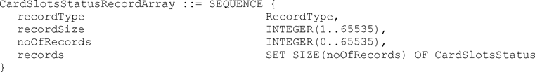
recordType denotes the type of the record (CardSlotsStatus). Value Assignment: See RecordType
recordSize is the size of the CardSlotsStatus in bytes.
noOfRecords is the number of records in the set records.
records is the set of CardSlotsStatus records.
2.36.CardStructureVersionU.K.
Code indicating the version of the implemented structure in a tachograph card.

Value assignment: ‘aabb’H:
‘aa’H
Index for changes of the structure.
‘00’H for Generation 1 applications
‘01’H for Generation 2 applications
‘bb’H
Index for changes concerning the use of the data elements defined for the structure given by the high byte.
‘00’H for this version of Generation 1 applications
‘00’H for this version of Generation 2 applications
2.37.CardVehicleRecordU.K.
Information, stored in a driver or workshop card, related to a period of use of a vehicle during a calendar day (Annex 1C requirements 269, 294, 322, and 345).
Generation 1:
vehicleOdometerBegin is the vehicle odometer value at the beginning of the period of use of the vehicle.
vehicleOdometerEnd is the vehicle odometer value at the end of the period of use of the vehicle.
vehicleFirstUse is the date and time of the beginning of the period of use of the vehicle.
vehicleLastUse is the date and time of the end of the period of use of the vehicle.
vehicleRegistration is the VRN and the registering Member State of the vehicle.
vuDataBlockCounter is the value of the VuDataBlockCounter at last extraction of the period of use of the vehicle.
Generation 2:
In addition to generation 1 the following data element is used:
VehicleIdentificationNumber is the vehicle identification number referring to the vehicle as a whole.


2.38.CardVehiclesUsedU.K.
Information, stored in a driver or workshop card, related to the vehicles used by the card holder (Annex 1C requirements 270, 295, 323, and 346).

vehiclePointerNewestRecord is the index of the last updated vehicle record.
Value assignment: Number corresponding to the numerator of the vehicle record, beginning with ‘0’ for the first occurrence of the vehicle records in the structure.
cardVehicleRecords is the set of records containing information on vehicles used.
2.39.CardVehicleUnitRecordU.K.
Generation 2:
Information, stored in a driver or workshop card, related to a vehicle unit that was used (Annex 1C requirement 303 and 351).

timeStamp is the beginning of the period of use of the vehicle unit (i.e. first card insertion in the vehicle unit for the period).
manufacturerCode identifies the manufacturer of the Vehicle Unit.
deviceID identifies the Vehicle Unit type of a manufacturer. The value is manufacturer specific.
vuSoftwareVersion is the software version number of the Vehicle Unit.
2.40.CardVehicleUnitsUsedU.K.
Generation 2:
Information, stored in a driver or workshop card, related to the vehicle units used by the card holder (Annex 1C requirement 306 and 352).

vehicleUnitPointerNewestRecord is the index of the last updated vehicle unit record.
Value assignment: Number corresponding to the numerator of the vehicle unit record, beginning with ‘0’ for the first occurrence of the vehicle unit records in the structure.
cardVehicleUnitRecords is the set of records containing information on vehicle units used.
2.41.CertificateU.K.
The certificate of a public key issued by a Certification Authority.
Generation 1:
Value assignment: digital signature with partial recovery of a CertificateContent according to Appendix 11 common security mechanisms: Signature (128 bytes) || Public Key remainder (58 bytes) || Certification Authority Reference (8 bytes).
Generation 2:
Value assignment: See Appendix 11


2.42.CertificateContentU.K.
Generation 1:
The (clear) content of the certificate of a public key according to Appendix 11 common security mechanisms.

certificateProfileIdentifier is the version of the corresponding certificate.
Value assignment: ‘01h’ for this version.
certificationAuthorityReference identifies the Certification Authority issuing the certificate. It also references the Public Key of this Certification Authority.
certificateHolderAuthorisation identifies the rights of the certificate holder.
certificateEndOfValidity is the date when the certificate expires administratively.
certificateHolderReference identifies the certificate holder. It also references his Public Key.
publicKey is the public key that is certified by this certificate.
2.43.CertificateHolderAuthorisationU.K.
Identification of the rights of a certificate holder.

Generation 1:
tachographApplicationID is the application identifier for the tachograph application.
Value assignment: ‘FFh’‘54h’‘41h’‘43h’‘48h’‘4Fh’. This AID is a proprietary non registered application identifier in accordance with ISO/IEC 7816-5.
equipmentType is the identification of the type of equipment to which the certificate is intended.
Value assignment: in accordance with EquipmentType data type. 0 if certificate is the one of a Member State.
Generation 2:
tachographApplicationID denotes the 6 most significant bytes of the generation 2 tachograph card application identifier (AID). The AID for the tachograph card application is specified in chapter 6.2.
Value assignment:‘FF 53 4D 52 44 54’.
equipmentType is the identification of the type of equipment as specified for generation 2 to which the certificate is intended.
Value assignment: in accordance with EquipmentType data type.
2.44.CertificateRequestIDU.K.
Unique identification of a certificate request. It can also be used as a Vehicle Unit Public Key Identifier if the serial number of the vehicle Unit to which the key is intended is not known at certificate generation time.

requestSerialNumber is a serial number for the certificate request, unique for the manufacturer and the month below.
requestMonthYear is the identification of the month and the year of the certificate request.
Value assignment: BCD coding of Month (two digits) and Year (two last digits).
crIdentifier: is an identifier to distinguish a certificate request from an extended serial number.
Value assignment: ‘FFh’.
manufacturerCode: is the numerical code of the manufacturer requesting the certificate.
2.45.CertificationAuthorityKIDU.K.
Identifier of the Public Key of a Certification Authority (a Member State or the European Certification Authority).

nationNumeric is the numerical nation code of the Certification Authority.
nationAlpha is the alphanumerical nation code of the Certification Authority.
keySerialNumber is a serial number to distinguish the different keys of the Certification Authority in the case keys are changed.
additionalInfo is a two byte field for additional coding (Certification Authority specific).
caIdentifier is an identifier to distinguish a Certification Authority Key Identifier from other Key Identifiers.
Value assignment: ‘01h’.
2.46.CompanyActivityDataU.K.
Information, stored in a company card, related to activities performed with the card (Annex 1C requirement 373 and 379).

companyPointerNewestRecord is the index of the last updated companyActivityRecord.
Value assignment: Number corresponding to the numerator of the company activity record, beginning with ‘0’ for the first occurrence of the company activity record in the structure.
companyActivityRecords is the set of all company activity records.
companyActivityRecord is the sequence of information related to one company activity.
companyActivityType is the type of the company activity.
companyActivityTime is the date and time of the company activity.
cardNumberInformation is the card number and the card issuing Member State of the card downloaded, if any.
vehicleRegistrationInformation is the VRN and registering Member State of the vehicle downloaded or locked in or out.
downloadPeriodBegin and downloadPeriodEnd is the period downloaded from the VU, if any.
2.47.CompanyActivityTypeU.K.
Code indicating an activity carried out by a company using its company card.

2.48.CompanyCardApplicationIdentificationU.K.
Information, stored in a company card related to the identification of the application of the card (Annex 1C requirement 369 and 375).

typeOfTachographCardId is specifying the implemented type of card.
cardStructureVersion is specifying the the version of the structure that is implemented in the card.
noOfCompanyActivityRecords is the number of company activity records the card can store.
2.49.CompanyCardHolderIdentificationU.K.
Information, stored in a company card, related to the cardholder identification (Annex 1C requirement 372 and 378).

companyName is the name of the holder company.
companyAddress is the address of the holder company.
cardHolderPreferredLanguage is the preferred language of the card holder.
2.50.ControlCardApplicationIdentificationU.K.
Information, stored in a control card related to the identification of the application of the card (Annex 1C requirement 357 and 363).

typeOfTachographCardId is specifying the implemented type of card.
cardStructureVersion is specifying the version of the structure that is implemented in the card.
noOfControlActivityRecords is the number of control activity records the card can store.
2.51.ControlCardControlActivityDataU.K.
Information, stored in a control card, related to control activity performed with the card (Annex 1C requirement 361 and 367).

controlPointerNewestRecord is the index of the last updated control activity record.
Value assignment: Number corresponding to the numerator of the control activity record, beginning with ‘0’ for the first occurrence of the control activity record in the structure.
controlActivityRecords is the set of all control activity records.
controlActivityRecord is the sequence of information related to one control.
controlType is the type of the control.
controlTime is the date and time of the control.
controlledCardNumber is the card number and the card issuing Member State of the card controlled.
controlledVehicleRegistration is the VRN and registering Member State of the vehicle in which the control happened.
controlDownloadPeriodBegin and controlDownloadPeriodEnd is the period eventually downloaded.
2.52.ControlCardHolderIdentificationU.K.
Information, stored in a control card, related to the identification of the cardholder (Annex 1C requirement 360 and 366).

controlBodyName is the name of the control body of the card holder.
controlBodyAddress is the address of the control body of the card holder.
cardHolderName is the name and first name(s) of the holder of the Control Card.
cardHolderPreferredLanguage is the preferred language of the card holder.
2.53.ControlTypeU.K.
Code indicating the activities carried out during a control. This data type is related to Annex 1C requirements 126, 274, 299, 327, and 350.

Generation 1:
Value assignment — Octet aligned: ‘cvpdxxxx’B (8 bits)
‘c’Bcard downloading:
‘0’B: card not downloaded during this control activity,
‘1’B: card downloaded during this control activity
‘v’BVU downloading:
‘0’B: VU not downloaded during this control activity,
‘1’B: VU downloaded during this control activity
‘p’Bprinting:
‘0’B: no printing done during this control activity,
‘1’B: printing done during this control activity
‘d’Bdisplay:
‘0’B: no display used during this control activity,
‘1’B: display used during this control activity
‘xxxx’BNot used.
Generation 2:
Value assignment — Octet aligned: ‘cvpdexxx’B (8 bits)
‘c’Bcard downloading:
‘0’B: card not downloaded during this control activity,
‘1’B: card downloaded during this control activity
‘v’BVU downloading:
‘0’B: VU not downloaded during this control activity,
‘1’B: VU downloaded during this control activity
‘p’Bprinting:
‘0’B: no printing done during this control activity,
‘1’B: printing done during this control activity
‘d’Bdisplay:
‘0’B: no display used during this control activity,
‘1’B: display used during this control activity
‘e’Broadside calibration checking:
‘0’B: calibration parameters not checked during this control activity,
‘1’B: calibration parameters checked during this control activity
‘xxx’BRFU.
2.54.CurrentDateTimeU.K.
The current date and time of the recording equipment.

Value assignment: not further specified.
2.55.CurrentDateTimeRecordArrayU.K.
Generation 2:
The current date and time plus metadata as used in the download protocol.

recordType denotes the type of the record (CurrentDateTime). Value Assignment: See RecordType
recordSize is the size of the CurrentDateTime in bytes.
noOfRecords is the number of records in the set records.
records is a set of current date and time records.
2.56.DailyPresenceCounterU.K.
Counter, stored in a driver or workshop card, increased by one for each calendar day the card has been inserted in a VU. This data type is related to Annex 1C requirements 266, 299, 320, and 343.

Value assignment: Consecutive Number with maximum value = 9 999, starting again with 0. At the time of first issuing of the card the number is set to 0.
2.57.DatefU.K.
Date expressed in a readily printable numeric format.

Value assignment:
yyyy
Year
mm
Month
dd
Day
‘00000000’H
denotes explicitly no date.
2.58.DateOfDayDownloadedU.K.
Generation 2:
The date and time of the download.

Value assignment: not further specified.
2.59.DateOfDayDownloadedRecordArrayU.K.
Generation 2:
The date and time of the download plus metadata as used in the download protocol.
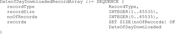
recordType denotes the type of the record (DateOfDayDownloaded). Value Assignment: See RecordType
recordSize is the size of the CurrentDateTime in bytes.
noOfRecords is the number of records in the set records.
records is the set of date and time of the download records.
2.60.DistanceU.K.
A distance travelled (result of the calculation of the difference between two vehicle's odometer values in kilometers).

Value assignment: Unsigned binary. Value in km in the operational range 0 to 9 999 km.
2.61.DriverCardApplicationIdentificationU.K.
Information, stored in a driver card related to the identification of the application of the card (Annex 1C requirement 253 and 278).
Generation 1:
typeOfTachographCardId is specifying the implemented type of card.
cardStructureVersion is specifying the the version of the structure that is implemented in the card.
noOfEventsPerType is the number of events per type of event the card can record.
noOfFaultsPerType is the number of faults per type of fault the card can record.
activityStructureLength indicates the number of bytes available for storing activity records.
noOfCardVehicleRecords is the number of vehicle records the card can contain.
noOfCardPlaceRecords is the number of places the card can record.
Generation 2:
[F2In addition to generation 1 the following data elements are used:
noOfGNSSADRecords is the number of GNSS accumulated driving records the card can store.
noOfSpecificConditionRecords is the number of specific condition records the card can store.
noOfCardVehicleUnitRecords is the number of vehicle units used records the card can store.]


2.62.DriverCardHolderIdentificationU.K.
Information, stored in a driver card, related to the identification of the cardholder (Annex 1C requirement 256 and 281).

cardHolderName is the name and first name(s) of the holder of the Driver Card.
cardHolderBirthDate is the date of birth of the holder of the Driver Card.
cardHolderPreferredLanguage is the preferred language of the card holder.
[F22.63. Reserved for future use] U.K.
2.64.EGFCertificateU.K.
Generation 2:
Certificate of the external GNSS facility public key for mutual authentication with a VU. The structure of this certificate is specified in Appendix 11.

2.65.EmbedderIcAssemblerIdU.K.
Provides information about the IC embedder.

countryCode is the 2 letter country code of the module embedder according to ISO 3166.
moduleEmbedder identifies the module embedder.
manufacturerInformation for manufacturer internal usage.
2.66.EntryTypeDailyWorkPeriodU.K.
Code to distinguish between begin and end for an entry of a daily work period place and condition of the entry.
Generation 1
Value assignment: according to ISO/IEC8824-1.
Generation 2
Value assignment: according to ISO/IEC8824-1.


2.67.EquipmentTypeU.K.
Code to distinguish different types of equipment for the tachograph application.

Generation 1:
Value assignment: According to ISO/IEC8824-1.
Value 0 is reserved for the purpose of designating a Member State or Europe in the CHA field of certificates.
Generation 2:
[F2The same values as in generation 1 are used with the following additions:
Note 1: The generation 2 values for the Plaque, Adapter and the External GNSS connection as well as the generation 1 values for the Vehicle Unit and Motion Sensor may be used in SealRecord, i.e. if applicable.U.K.
Note 2: In the CardHolderAuthorisation (CHA) field of a generation 2 certificate, the values (1), (2), and (6) are to be interpreted as indicating a certificate for Mutual Authentication for the respective equipment type. For indicating the respective certificate for creating a digital signature, the values (17), (18) or (19) must be used.]U.K.


2.68.EuropeanPublicKeyU.K.
Generation 1:
The European public key.

2.69.EventFaultRecordPurposeU.K.
Code explaining why an event or a fault has been recorded.

Value assignment:
 | one of the 10 most recent (or last) events or faults the longest event for one of the last 10 days of occurrence one of the 5 longest events over the last 365 days the last event for one of the last 10 days of occurrence the most serious event for one of the last 10 days of occurrence one of the 5 most serious events over the last 365 days the first event or fault having occurred after the last calibration an active/on-going event or fault RFU manufacturer specific |
2.70.EventFaultTypeU.K.
Code qualifying an event or a fault.

Value assignment:
Generation 1:
General events,
No further details,
Insertion of a non valid card,
Card conflict,
Time overlap,
Driving without an appropriate card,
Card insertion while driving,
Last card session not correctly closed,
Over speeding,
Power supply interruption,
Motion data error,
Vehicle Motion Conflict,
RFU,
Vehicle unit related security breach attempt events,
No further details,
Motion sensor authentication failure,
Tachograph card authentication failure,
Unauthorised change of motion sensor,
Card data input integrity error
Stored user data integrity error,
Internal data transfer error,
Unauthorised case opening,
Hardware sabotage,
RFU,
Sensor related security breach attempt events,
No further details,
Authentication failure,
Stored data integrity error,
Internal data transfer error,
Unauthorised case opening,
Hardware sabotage,
RFU,
Recording equipment faults,
No further details,
VU internal fault,
Printer fault,
Display fault,
Downloading fault,
Sensor fault,
RFU,
Card faults,
No further details,
RFU,
RFU, Manufacturer specific. [F2Generation 2:
General events,
No further details,
Insertion of a non valid card,
Card conflict,
Time overlap,
Driving without an appropriate card,
Card insertion while driving,
Last card session not correctly closed,
Over speeding,
Power supply interruption,
Motion data error,
Vehicle Motion Conflict,
Time conflict (GNSS versus VU internal clock),
Communication error with the remote communication facility,
Absence of position information from GNSS receiver,
Communication error with the external GNSS facility,
RFU,
Vehicle unit related security breach attempt events,
No further details,
Motion sensor authentication failure,
Tachograph card authentication failure,
Unauthorised change of motion sensor,
Card data input integrity error
Stored user data integrity error,
Internal data transfer error,
Unauthorised case opening,
Hardware sabotage,
Tamper detection of GNSS,
External GNSS facility authentication failure,
External GNSS facility certificate expired,
RFU,
Sensor related security breach attempt events,
No further details,
Authentication failure,
Stored data integrity error,
Internal data transfer error,
Unauthorised case opening,
Hardware sabotage,
RFU,
Recording equipment faults,
No further details,
VU internal fault,
Printer fault,
Display fault,
Downloading fault,
Sensor fault,
Internal GNSS receiver,
External GNSS facility,
Remote communication facility,
ITS interface,
RFU,
Card faults,
No further details,
RFU,
RFU, Manufacturer specific.]

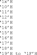


[F22.71. ExtendedSealIdentifier U.K.
Generation 2:
The extended seal identifier uniquely identifies a seal (Annex IC requirement 401).

manufacturerCode is a code of the manufacturer of the seal.
sealIdentifier is an identifier for the seal which is unique for the manufacturer.]
2.72.ExtendedSerialNumberU.K.
Unique identification of an equipment. It can also be used as an equipment Public Key Identifier.
Generation 1:
serialNumber is a serial number for the equipment, unique for the manufacturer, the equipment's type and the month and year below.
monthYear is the identification of the month and the year of manufacturing (or of serial number assignment).
Value assignment: BCD coding of Month (two digits) and Year (two last digits).
type is an identifier of the type of equipment.
Value assignment: manufacturer specific, with ‘FFh’ reserved value.
manufacturerCode: is the numerical code identifying a manufacturer of type approved equipment.
Generation 2:
serialNumber see Generation 1
monthYear see Generation 1
type indicates the type of equipment
manufacturerCode: see Generation 1.


2.73.FullCardNumberU.K.
Code fully identifying a tachograph card.

cardType is the type of the tachograph card.
cardIssuingMemberState is the code of the Member State having issued the card.
cardNumber is the card number.
2.74.FullCardNumberAndGenerationU.K.
Generation 2:
Code fully identifying a tachograph card and its generation.

fullcardNumber identifies the tachograph card.
generation indicates the generation of the tachograph card used.
2.75.GenerationU.K.
Generation 2:
Indicates the generation of tachograph used.

Value assignment:
‘00’H
RFU
‘01’H
Generation 1
‘02’H
Generation 2
‘03’H .. ‘FF’H
RFU
2.76.GeoCoordinatesU.K.
Generation 2:
The geo-coordinates are encoded as integers. These integers are multiples of the ±DDMM.M encoding for the latitude and ±DDDMM.M for the longitude. Here ±DD respectively ±DDD denotes the degrees and MM.M the minutes.

latitude is encoded as a multiple (factor 10) of the ±DDMM.M representation.
longitude is encoded as a multiple (factor 10) of the ±DDDMM.M representation.
2.77.GNSSAccuracyU.K.
Generation 2:
The accuracy of the GNSS position data (definition eee)). This accuracy is encoded as integer and is a multiple (factor 10) of the X.Y value provided by the GSA NMEA sentence.

[F22.78. GNSSAccumulatedDriving U.K.
Generation 2:
Information, stored in a driver or workshop card, related to the GNSS position of the vehicle if the accumulated driving time reaches a multiple of three hours (Annex IC requirement 306 and 354).

gnssADPointerNewestRecord is the index of the last updated GNSS accumulated driving record.
Value assignment is the number corresponding to the numerator of the GNSS accumulated driving record, beginning with '0' for the first occurrence of the GNSS accumulated driving record in the structure.
gnssAccumulatedDrivingRecords is the set of records containing the date and time the accumulated driving reaches a multiple of three hours and information on the position of the vehicle.
2.79. GNSSAccumulatedDrivingRecord U.K.
Generation 2:
Information, stored in a driver or workshop card, related to the GNSS position of the vehicle if the accumulated driving time reaches a multiple of three hours (Annex IC requirement 305 and 353)

timeStamp is the date and time when the accumulated driving time reaches a multiple of three hours.
gnssPlaceRecord contains information related to the position of the vehicle.
vehicleOdometerValue is the odometer value when the accumulated driving time reaches a multiple of three hours.]
2.80.GNSSPlaceRecordU.K.
Generation 2:
Information related to the GNSS position of the vehicle (Annex 1C requirements 108, 109, 110, 296, 305, 347, and 353).

timeStamp is the date and time when the GNSS position of the vehicle was determined.
gnssAccuracy is the accuracy of the GNSS position data.
geoCoordinates is the recorded location using GNSS.
2.81.HighResOdometerU.K.
Odometer value of the vehicle: Accumulated distance travelled by the vehicle during its operation.

Value assignment: Unsigned binary. Value in 1/200 km in the operating range 0 to 21 055 406 km.
2.82.HighResTripDistanceU.K.
A distance travelled during all or part of a journey.

Value assignment: Unsigned binary. Value in 1/200 km in the operating range 0 to 21 055 406 km.
2.83.HolderNameU.K.
The surname and first name(s) of a card holder.

holderSurname is the surname (family name) of the holder. This surname does not include titles.
Value assignment: When a card is not personal, holderSurname contains the same information as companyName or workshopName or controlBodyName.
holderFirstNames is the first name(s) and initials of the holder.
2.84.InternalGNSSReceiverU.K.
Generation 2:
Information if the GNSS receiver is internal or external to the vehicle unit. True means that the GNSS receiver is internal to the VU. False means that the GNSS receiver is external.

2.85.K-ConstantOfRecordingEquipmentU.K.
Constant of the recording equipment (definition m)).

Value assignment: Pulses per kilometer in the operating range 0 to 64 255 pulses/km.
[F22.86. KeyIdentifier U.K.
A unique identifier of a Public Key used to reference and select the key. It also identifies the holder of the key.

The first choice is suitable to reference the public key of a Vehicle Unit, of a tachograph card or of an external GNSS facility.
The second choice is suitable to reference the public key of a Vehicle Unit (in cases where the serial number of the Vehicle Unit cannot be known at certificate generation time).
The third choice is suitable to reference the public key of a Member State.]
2.87.KMWCKeyU.K.
Generation 2:
AES key and its associated key version used for VU — Motion Sensor pairing. For details see Appendix 11.

kMWCKey is the length of the AES key concatenated with the key which is used for VU — Motion Sensor pairing.
keyVersion denotes the key version of the AES key.
2.88.LanguageU.K.
Code identifying a language.

Value assignment: Two-letter lower-case coding according to ISO 639.
2.89.LastCardDownloadU.K.
Date and time, stored on a driver card, of last card download (for other purposes than control) Annex 1C requirement 257 and 282. This date is updateable by a VU or any card reader.

Value assignment: not further specified.
2.90.LinkCertificateU.K.
Generation 2:
The link certificate between European Root CA key pairs.

2.91.L-TyreCircumferenceU.K.
Effective circumference of the wheel tyres (definition u)).

Value assignment: Unsigned binary, value in 1/8 mm in the operating range 0 to 8 031 mm.
[F22.92. MAC U.K.
Generation 2:
A cryptographic check sum of 8, 12 or 16 bytes length corresponding to the cipher suites specified in Appendix 11.]

2.93.ManualInputFlagU.K.
Code identifying whether a cardholder has manually entered driver activities at card insertion or not (Annex 1B requirement 081 and Annex 1C requirement 102).

Value assignment: not further specified.
2.94.ManufacturerCodeU.K.
Code identifying a manufacturer of type approved equipment.

The laboratory competent for interoperability tests maintains and publishes the list of manufacturer codes on its web site (Annex 1C requirement 454).
ManufacturerCodes are provisionally assigned to developers of tachograph equipment on application to the laboratory competent for interoperability tests.
2.95.ManufacturerSpecificEventFaultDataU.K.
Generation 2:
Manufacturer specific error codes simplify the error analysis and maintenance of vehicle units.

manufacturerCode identifies the manufacturer of the Vehicle Unit.
manufacturerSpecificErrorCode is an error code specific to the manufacturer.
2.96.MemberStateCertificateU.K.
The certificate of the public key of a member state issued by the European certification authority.

2.97.MemberStateCertificateRecordArrayU.K.
Generation 2:
The member state certificate plus metadata as used in the download protocol.

recordType denotes the type of the record (MemberStateCertificate). Value Assignment: See RecordType
recordSize is the size of the MemberStateCertificate in bytes.
noOfRecords is the number of records in the set records. The value shall be set to 1 as the certficates may have different lengths.
records is the set of member state certificates.
2.98.MemberStatePublicKeyU.K.
Generation 1:
The public key of a Member State.

2.99.NameU.K.
A name.

codePage specifies a character set defined in Chapter 4,
name is a name encoded using the specified character set.
2.100.NationAlphaU.K.
Alphabetic reference to a country shall be in accordance with the distinguishing signs used on vehicles in international traffic (United Nations Vienna Convention on Road Traffic, 1968).

The Nation Alpha and Numeric codes shall be held on a list maintained on the website of the laboratory appointed to carry out interoperability testing, as set out in Annex 1C requirement 440.
2.101.NationNumericU.K.
Numerical reference to a country.

Value assignment: see data type 2.100 (NationAlpha).
Any amendment or updating of the Nation Alpha or Numeric specification described in the above paragraph shall only be made out after the appointed laboratory has obtained the views of type approved digital and smart tachograph vehicle unit manufacturers.
2.102.NoOfCalibrationRecordsU.K.
Number of calibration records, a workshop card can store.


2.103.NoOfCalibrationsSinceDownloadU.K.
Counter indicating the number of calibrations performed with a workshop card since its last download (Annex 1C requirement 317 and 340).

Value assignment: Not specified further.
2.104.NoOfCardPlaceRecordsU.K.
Number of place records a driver or workshop card can store.


2.105.NoOfCardVehicleRecordsU.K.
Number of vehicles used records a driver or workshop card can store.

Value assignment: see Appendix 2.
2.106.NoOfCardVehicleUnitRecordsU.K.
Generation 2:
Number of vehicle units used records a driver or workshop card can store.

Value assignment: see Appendix 2.
2.107.NoOfCompanyActivityRecordsU.K.
Number of company activity records, a company card can store.

Value assignment: see Appendix 2.
2.108.NoOfControlActivityRecordsU.K.
Number of control activity records, a control card can store.

Value assignment: see Appendix 2.
2.109.NoOfEventsPerTypeU.K.
Number of events per type of event a card can store.

Value assignment: see Appendix 2.
2.110.NoOfFaultsPerTypeU.K.
Number of faults per type of fault a card can store.

Value assignment: see Appendix 2.
[F22.111. NoOfGNSSADRecords U.K.
Generation 2:
Number of GNSS accumulated driving records a card can store.

Value assignment: see Appendix 2.]
2.112.NoOfSpecificConditionRecordsU.K.
Generation 2:
Number of specific condition records a card can store.

Value assignment: see Appendix 2.
2.113.OdometerShortU.K.
Odometer value of the vehicle in a short form.

Value assignment: Unsigned binary. Value in km in the operating range 0 to 9 999 999 km.
2.114.OdometerValueMidnightU.K.
The vehicle's odometer value at midnight on a given day (Annex 1B requirement 090 and Annex 1C requirement 113).

Value assignment: not further specified.
2.115.OdometerValueMidnightRecordArrayU.K.
Generation 2:
The OdometerValueMidnight plus metadata used in the download protocol.

recordType denotes the type of the record (OdometerValueMidnight). Value Assignment: See RecordType
recordSize is the size of the OdometerValueMidnight in bytes.
noOfRecords is the number of records in the set records.
records is the set of OdometerValueMidnight records.
2.116.OverspeedNumberU.K.
Number of over speeding events since the last over speeding control.

Value assignment: 0 means that no over speeding event has occurred since the last over speeding control, 1 means that one over speeding event has occurred since the last over speeding control …255 means that 255 or more over speeding events have occurred since the last over speeding control.
2.117.PlaceRecordU.K.
Information related to a place where a daily work period begins or ends (Annex 1C requirements 108, 271, 296, 324, and 347).
Generation 1:
entryTime is a date and time related to the entry.
entryTypeDailyWorkPeriod is the type of entry.
dailyWorkPeriodCountry is the country entered.
dailyWorkPeriodRegion is the region entered.
vehicleOdometerValue is the odometer value at the time of place entry.
Generation 2:
In addition to Generation 1 the following component is used:
entryGNSSPlaceRecord is the recorded location and time.


2.118.PreviousVehicleInfoU.K.
Information related to the vehicle previously used by a driver when inserting his card in a vehicle unit (Annex 1B requirement 081 and Annex 1C requirement 102).
Generation 1:
vehicleRegistrationIdentification is the VRN and the registering Member State of the vehicle.
cardWithdrawalTime is the card withdrawal date and time.
Generation 2:
In addition to generation 1 the following data element is used:
vuGeneration identifies the generation of the vehicle unit.


2.119.PublicKeyU.K.
Generation 1:
A public RSA key.

rsaKeyModulus is the Modulus of the key pair.
rsaKeyPublicExponent is the public exponent of the key pair.
2.120.RecordTypeU.K.
Generation 2:
Reference to a record type. This data type is used in RecordArrays.

Value assignment:
 | ActivityChangeInfo, CardSlotsStatus, CurrentDateTime, MemberStateCertificate, OdometerValueMidnight, DateOfDayDownloaded, SensorPaired, Signature, SpecificConditionRecord, VehicleIdentificationNumber, VehicleRegistrationNumber, VuCalibrationRecord, VuCardIWRecord, VuCardRecord, VuCertificate, VuCompanyLocksRecord, VuControlActivityRecord, VuDetailedSpeedBlock, VuDownloadablePeriod, VuDownloadActivityData, VuEventRecord, [F2VuGNSSADRecord,] VuITSConsentRecord, VuFaultRecord, VuIdentification, VuOverSpeedingControlData, VuOverSpeedingEventRecord, VuPlaceDailyWorkPeriodRecord, VuTimeAdjustmentGNSSRecord, VuTimeAdjustmentRecord, VuPowerSupplyInterruptionRecord, SensorPairedRecord, SensorExternalGNSSCoupledRecord, RFU, Manufacturer specific. |
2.121.RegionAlphaU.K.
Alphabetic reference to a region within a specified country.

Generation 1:
Value assignment:
Generation 2:
The RegionAlpha codes shall be held on a list maintained on the website of the laboratory appointed to carry out interoperability testing.

2.122.RegionNumericU.K.
Numerical reference to a region within a specified country.

Generation 1:
Value assignment:
Generation 2:
The RegionNumeric codes shall be held on a list maintained on the website of the laboratory appointed to carry out interoperability testing.

2.123.RemoteCommunicationModuleSerialNumberU.K.
Generation 2:
Serial number of the Remote Communication Module.

2.124.RSAKeyModulusU.K.
Generation 1:
The modulus of a RSA key pair.

Value assignment: Unspecified.
2.125.RSAKeyPrivateExponentU.K.
Generation 1:
The private exponent of a RSA key pair.

Value assignment: Unspecified.
2.126.RSAKeyPublicExponentU.K.
Generation1:
The public exponent of a RSA key pair.

Value assignment: Unspecified.
2.127.RtmDataU.K.
Generation2:
For the definition of this data type see Appendix 14.
2.128.SealDataCardU.K.
Generation 2:
This data type stores information about the seals that are attached to the different components of a vehicle and is intended for storage on a card. This data type is related to Annex 1C requirement 337.

noOfSealRecords is the number of records in sealRecords.
sealRecords is a set of seal records.
2.129.SealDataVuU.K.
Generation 2:
This data type stores information about the seals that are attached to the different components of a vehicle and is intended for storage in a Vehicle Unit.

sealRecords is a set of seal records. If there are less than 5 seals available the value of the EquipmentType in all unused sealRecords shall be set to 16, i.e. unused.
2.130.SealRecordU.K.
Generation 2:
This data type stores information about a seal that is attached to a component. This data type is related to Annex 1C requirement 337.

equipmentType identifies the type of equipment the seal is attached to.
extendedSealIdentifier is the identifier of the seal attached to the equipment.
2.131.SensorApprovalNumberU.K.
Type approval number of the sensor.
Generation 1:
Value assignment: Unspecified.
Generation 2:
Value assignment:
The approval number shall be provided as published on the corresponding European Commission web site, i.e. for example including hyphens if any. The approval number shall be left-aligned.


2.132.SensorExternalGNSSApprovalNumberU.K.
Generation 2:
Type approval number of the external GNSS facility.

Value assignment:
The approval number shall be provided as published on the corresponding European Commission web site, i.e. for example including hyphens if any. The approval number shall be left-aligned.
2.133.SensorExternalGNSSCoupledRecordU.K.
Generation 2:
Information, stored in a vehicle unit, related to the identification of the external GNSS facility coupled with the vehicle unit (Annex 1C requirement 100).

sensorSerialNumber is the serial number of the external GNSS facility coupled with the vehicle unit.
sensorApprovalNumber is the approval number of this external GNSS facility.
sensorCouplingDate is a date of coupling of this external GNSS facility with the vehicle unit.
2.134.SensorExternalGNSSIdentificationU.K.
Generation 2:
Information related to the identification of the external GNSS facility (Annex 1C requirement 98).

sensorSerialNumber is the extended serial number of the external GNSS facility.
sensorApprovalNumber is the approval number of the external GNSS facility.
sensorSCIdentifier is the identifier of the security component of the external GNSS facility.
sensorOSIdentifier is the identifier of the operating system of the external GNSS facility.
2.135.SensorExternalGNSSInstallationU.K.
Generation 2:
Information, stored in an external GNSS facility, related to the installation of the external GNSS sensor (Annex 1C requirement 123).

sensorCouplingDateFirst is the date of the first coupling of external GNSS facility with a vehicle unit.
firstVuApprovalNumber is the approval number of the first vehicle unit coupled with the external GNSS facility.
firstVuSerialNumber is the serial number of the first vehicle unit paired with the external GNSS facility.
sensorCouplingDateCurrent is the date of the current coupling of external GNSS facility with a vehicle unit.
currentVuApprovalNumber is the approval number of the vehicle unit currently coupled with the external GNSS facility.
currentVUSerialNumber is the serial number of the vehicle unit currently coupled with the external GNSS facility.
2.136.SensorExternalGNSSOSIdentifierU.K.
Generation 2:
Identifier of the operating system of the external GNSS facility.

Value assignment: manufacturer specific.
2.137.SensorExternalGNSSSCIdentifierU.K.
Generation 2:
This type is used e.g. to identify the cryptographic module of the external GNSS facility.
Identifier of the security component of the external GNSS facility.

Value assignment: component manufacturer specific.
2.138.SensorGNSSCouplingDateU.K.
Generation 2:
Date of a coupling of the external GNSS facility with a vehicle unit.

Value assignment: Unspecified.
2.139.SensorGNSSSerialNumberU.K.
Generation 2:
This type is used to store the serial number of the GNSS receiver both when it is inside the VU and when it is outside the VU.
Serial number of the GNSS receiver.

2.140.SensorIdentificationU.K.
Information, stored in a motion sensor, related to the identification of the motion sensor (Annex 1B requirement 077 and Annex 1C requirement 95).
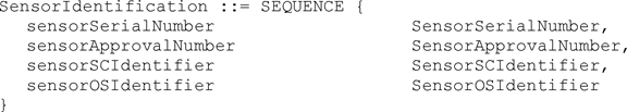
sensorSerialNumber is the extended serial number of the motion sensor (includes part number and manufacturer code).
sensorApprovalNumber is the approval number of the motion sensor.
sensorSCIdentifier is the identifier of the security component of the motion sensor.
sensorOSIdentifier is the identifier of the operating system of the motion sensor.
2.141.SensorInstallationU.K.
Information, stored in a motion sensor, related to the installation of the motion sensor (Annex 1B requirement 099 and Annex 1C requirement 122).

sensorPairingDateFirst is the date of the first pairing of the motion sensor with a vehicle unit.
firstVuApprovalNumber is the approval number of the first vehicle unit paired with the motion sensor.
firstVuSerialNumber is the serial number of the first vehicle unit paired with the motion sensor.
sensorPairingDateCurrent is the date of the current pairing of the motion sensor with the vehicle unit.
currentVuApprovalNumber is the approval number of the vehicle unit currently paired with the motion sensor.
currentVUSerialNumber is the serial number of the vehicle unit currently paired with the motion sensor.
2.142.SensorInstallationSecDataU.K.
Information, stored in a workshop card, related to the security data needed for pairing motion sensors to vehicle units (Annex 1C requirement 308 and 331).
Generation 1:
Value assignment: in accordance with ISO 16844-3.
Generation 2:
As described in Appendix 11 a workshop card shall store up to three keys for VU Motion Sensor pairing. These keys have different key versions.


2.143.SensorOSIdentifierU.K.
Identifier of the operating system of the motion sensor.

Value assignment: manufacturer specific.
2.144.SensorPairedU.K.
Generation 1:
Information, stored in a vehicle unit, related to the identification of the motion sensor paired with the vehicle unit (Annex 1B requirement 079).

sensorSerialNumber is the serial number of the motion sensor currently paired with the vehicle unit.
sensorApprovalNumber is the approval number of the motion sensor currently paired with the vehicle unit.
sensorPairingDateFirst is the date of the first pairing with a vehicle unit of the motion sensor currently paired with the vehicle unit.
2.145.SensorPairedRecordU.K.
Generation 2:
Information, stored in a vehicle unit, related to the identification of a motion sensor paired with the vehicle unit (Annex 1C requirement 97).

sensorSerialNumber is the serial number of a motion sensor paired with the vehicle unit.
sensorApprovalNumber is the approval number of this motion sensor.
sensorPairingDate is a date of pairing of this motion sensor with the vehicle unit.
2.146.SensorPairingDateU.K.
Date of a pairing of the motion sensor with a vehicle unit.

Value assignment: Unspecified.
2.147.SensorSCIdentifierU.K.
Identifier of the security component of the motion sensor.

Value assignment: component manufacturer specific.
2.148.SensorSerialNumberU.K.
Serial number of the motion sensor.

2.149.SignatureU.K.
A digital signature.
Generation 1:
Value assignment: in accordance with Appendix 11 Common security mechanisms.
Generation 2:
Value assignment: in accordance with Appendix 11 Common security mechanisms.


2.150.SignatureRecordArrayU.K.
Generation 2:
A set of signatures plus metadata used in the download protocol.

recordType denotes the type of the record (Signature). Value Assignment: See RecordType
recordSize is the size of the Signature in bytes.
noOfRecords is the number of records in the set records. The value shall be set to 1 as the signatures may have different lengths.
records is the set of signatures.
2.151.SimilarEventsNumberU.K.
The number of similar events for one given day (Annex 1B requirement 094 and Annex 1C requirement 117).

Value assignment: 0 is not used, 1 means that only one event of that type has occurred and has been stored on that day, 2 means that 2 events of that type has occurred on that day (one only has been stored), …255 means that 255 or more events of that type have occurred on that day.
2.152.SpecificConditionRecordU.K.
Information, stored in a driver card, a workshop card or a vehicle unit, related to a specific condition (requirements Annex 1C 130, 276, 301, 328, and 355).

entryTime is the date and time of the entry.
specificConditionType is the code identifying the specific condition.
2.153.SpecificConditionsU.K.
Information, stored in a driver card, a workshop card or a vehicle unit, related to a specific condition (Annex 1C requirement 131, 277, 302, 329, and 356).
Generation 2:

conditionPointerNewestRecord is the index of the last updated specific condition record.
Value assignment: Number corresponding to the numerator of the specific condition record, beginning with ‘0’ for the first occurrence of the specific condition record in the structure.
specificConditionRecords is the set of records containing information on the specific conditions recorded.
2.154.SpecificConditionTypeU.K.
Code identifying a specific condition (Annex 1B requirements 050b, 105a, 212a and 230a and Annex 1C requirements 62).

Generation 1:
Value assignment:
‘00’HRFU
‘01’HOut of scope — Begin
‘02’HOut of scope — End
‘03’HFerry / Train crossing
‘04’H .. ‘FF’HRFU
Generation 2:
Value assignment:
‘00’HRFU
‘01’HOut of scope — Begin
‘02’HOut of scope — End
‘03’HFerry / Train crossing — Begin
‘04’HFerry / Train crossing — End
‘05’H .. ‘FF’HRFU
2.155.SpeedU.K.
Speed of the vehicle (km/h).

Value assignment: kilometers per hour in the operational range 0 to 220 km/h.
2.156.SpeedAuthorisedU.K.
Maximum authorised Speed of the vehicle (definition hh)).

2.157.SpeedAverageU.K.
Average speed in a previously defined duration (km/h).

2.158.SpeedMaxU.K.
Maximum speed measured in a previously defined duration.

2.159.TachographPayloadU.K.
Generation 2:
For the definition of this data type see Appendix 14.
[F22.160. Reserved for future use] U.K.
2.161.TDesSessionKeyU.K.
Generation 1:
A triple DES session key.

Value assignment: not further specified.
[F22.162. TimeReal U.K.
Code for a combined date and time field, where the date and time are expressed as seconds past 00h.00m.00s. on 1 January 1970 UTC.

Value assignment – Octet aligned : Number of seconds since midnight 1 January 1970 UTC.
The max. possible date/time is in the year 2106.]
2.163.TyreSizeU.K.
Designation of tyre dimensions.

Value assignment: in accordance with Directive 92/23 (EEC) 31/03/92 O.J. L129 p.95.
2.164.VehicleIdentificationNumberU.K.
Vehicle Identification Number (VIN) referring to the vehicle as a whole, normally chassis serial number or frame number.

Value assignment: As defined in ISO 3779.
2.165.VehicleIdentificationNumberRecordArrayU.K.
Generation 2:
The Vehicle Idenification Number plus metadata as used in the download protocol.

recordType denotes the type of the record (VehicleIdentificationNumber). Value Assignment: See RecordType
recordSize is the size of the VehicleIdentificationNumber in bytes.
noOfRecords is the number of records in the set records.
records is the set of vehicle identification numbers.
2.166.VehicleRegistrationIdentificationU.K.
Identification of a vehicle, unique for Europe (VRN and Member State).

vehicleRegistrationNation is the nation where the vehicle is registered.
vehicleRegistrationNumber is the registration number of the vehicle (VRN).
2.167.VehicleRegistrationNumberU.K.
Registration number of the vehicle (VRN). The registration number is assigned by the vehicle licensing authority.

codePage specifies a character set defined in Chapter 4,
vehicleRegNumber is a VRN encoded using the specified character set.
Value assignment: Country specific.
2.168.VehicleRegistrationNumberRecordArrayU.K.
Generation 2:
The Vehicle Registration Number plus metadata as used in the download protocol.

recordType denotes the type of the record (VehicleRegistrationNumber). Value Assignment: See RecordType
recordSize is the size of the VehicleRegistrationNumber in bytes.
noOfRecords is the number of records in the set records.
records is the set of vehicle registration numbers.
2.169.VuAbilityU.K.
Generation 2:
Information stored in a VU on the ability of the VU to use generation 1 tachograph cards or not (Annex 1C requirement 121).

Value assignment — Octet Aligned:‘xxxxxxxa’B (8 bits)
For the ability to support of generation 1:
‘a’B
Ability to support generation 1 tachograph cards:
‘0’ B Generation 1 is supported,
‘1’B Generation1 is not supported,
‘xxxxxxx’B
RFU
2.170.VuActivityDailyDataU.K.
Generation 1:
Information, stored in a VU, related to changes of activity and/or changes of driving status and/or changes of card status for a given calendar day (Annex 1B requirement 084 and Annex 1C requirement 105, 106, 107) and to slots status at 00:00 that day.

noOfActivityChanges is the number of ActivityChangeInfo words in the activityChangeInfos set.
activityChangeInfos is the set of ActivityChangeInfo words stored in the VU for the day. It always includes two ActivityChangeInfo words giving the status of the two slots at 00:00 that day.
2.171.VuActivityDailyRecordArrayU.K.
Generation 2:
Information, stored in a VU, related to changes of activity and/or changes of driving status and/or changes of card status for a given calendar day (Annex 1C requirement 105, 106, 107) and to slots status at 00:00 that day.

recordType denotes the type of the record (ActivityChangeInfo). Value Assignment: See RecordType
recordSize is the size of the ActivityChangeInfo in bytes.
noOfRecords is the number of records in the set records.
records is the set of ActivityChangeInfo words stored in the VU for the day. It always includes two ActivityChangeInfo words giving the status of the two slots at 00:00 that day.
2.172.VuApprovalNumberU.K.
Type approval number of the vehicle unit.
Generation 1:
Value assignment: Unspecified.
Generation 2:
Value assignment:
The approval number shall be provided as published on the corresponding European Commission web site, i.e. for example including hyphens if any. The approval number shall be left-aligned.


2.173.VuCalibrationDataU.K.
Generation 1:
Information, stored in a vehicle unit, related to the calibrations of the recording equipment (Annex 1B requirement 098).

noOfVuCalibrationRecords is the number of records contained in the vuCalibrationRecords set.
vuCalibrationRecords is the set of calibration records.
2.174.VuCalibrationRecordU.K.
Information, stored in a vehicle unit, related a calibration of the recording equipment (Annex 1B requirement 098 and Annex 1C requirement 119 and 120).
Generation 1:
calibrationPurpose is the purpose of the calibration.
workshopName, workshopAddress are the workshop name and address.
workshopCardNumber identifies the workshop card used during the calibration.
workshopCardExpiryDate is the card expiry date.
vehicleIdentificationNumber is the VIN.
vehicleRegistrationIdentification contains the VRN and registering Member State.
wVehicleCharacteristicConstant is the characteristic coefficient of the vehicle.
kConstantOfRecordingEquipment is the constant of the recording equipment.
lTyreCircumference is the effective circumference of the wheel tyres.
tyreSize is the designation of the dimension of the tyres mounted on the vehicle
authorisedSpeed is the authorised speed of the vehicle.
oldOdometerValue, newOdometerValue are the old and new values of the odometer.
oldTimeValue, newTimeValue are the old and new values of date and time.
nextCalibrationDate is the date of the next calibration of the type specified in CalibrationPurpose to be carried out by the authorised inspection authority.
Generation 2:
In addition to generation 1 the following data element is used:
sealDataVu gives information about the seals that are attached to different components of the vehicle.


2.175.VuCalibrationRecordArrayU.K.
Generation 2:
Information, stored in a vehicle unit, related to the calibrations of the recording equipment (Annex 1C requirement 119 and 120).

recordType denotes the type of the record (VuCalibrationRecord). Value Assignment: See RecordType
recordSize is the size of the VuCalibrationRecord in bytes.
noOfRecords is the number of records in the set records.
records is the set of calibration records.
2.176.VuCardIWDataU.K.
Generation 1:
Information, stored in a vehicle unit, related to insertion and withdrawal cycles of driver cards or of workshop cards in the vehicle unit (Annex 1B requirement 081 and Annex 1C requirement 103).

noOfIWRecords is the number of records in the set vuCardIWRecords.
vuCardIWRecords is a set of records related to card insertion withdrawal cycles.
2.177.VuCardIWRecordU.K.
Information, stored in a vehicle unit, related to an insertion and withdrawal cycle of a driver card or of a workshop card in the vehicle unit (Annex 1B requirement 081 and Annex 1C requirement 102).
Generation 1:
cardHolderName is the driver or workshop card holder's surname and first names as stored in the card.
fullCardNumber is the type of card, its issuing Member State and its card number as stored in the card.
cardExpiryDate is the card's expiry date as stored in the card.
cardInsertionTime is the insertion date and time.
vehicleOdometerValueAtInsertion is the vehicle odometer value at card insertion.
cardSlotNumber is the slot in which the card is inserted.
cardWithdrawalTime is the withdrawal date and time.
vehicleOdometerValueAtWithdrawal is the vehicle odometer value at card withdrawal.
previousVehicleInfo contains information about the previous vehicle used by the driver, as stored in the card.
manualInputFlag is a flag identifying if the cardholder has manually entered driver activities at card insertion.
Generation 2:
Instead of fullCardNumber the generation 2 data structure makes use of the following data element.
fullCardNumberAndGeneration is the type of card, its issuing Member State, its card number and generation as stored in the card.


2.178.VuCardIWRecordArrayU.K.
Generation 2:
Information, stored in a vehicle unit, related to insertion and withdrawal cycles of driver cards or of workshop cards in the vehicle unit (Annex 1C requirement 103).

recordType denotes the type of the record (VuCardIWRecord). Value Assignment: See RecordType
recordSize is the size of the VuCardIWRecord in bytes.
noOfRecords is the number of records in the set records.
records is a set of records related to card insertion withdrawal cycles.
[F22.179. VuCardRecord U.K.
Generation 2:
Information, stored in a vehicle unit, about a tachograph card used (Annex IC requirement 132).

cardNumberAndGenerationInformation is the full card number and generation of the card used (data type 2.74).
cardExtendedSerialNumber as read from the file EF_ICC under the MF of the card.
cardStructureVersion as read from the file EF_Application_Identification under the DF_Tachograph_G2.
cardNumber as read from the file EF_Identification under the DF_Tachograph_G2.]
2.180.VuCardRecordArrayU.K.
Generation 2:
Information stored in a vehicle unit about the tachograph cards used with this VU. This information is intended for the analysis of VU — card problems (Annex 1C requirement 132).

recordType denotes the type of the record (VuCardRecord). Value Assignment: See RecordType
recordSize is the size of the VuCardRecord in bytes.
noOfRecords is the number of records in the set records.
records is a set of records related to the tachograph cards used with the VU.
2.181.VuCertificateU.K.
Certificate of the public key of a vehicle unit.

2.182.VuCertificateRecordArrayU.K.
Generation 2:
The VU certificate plus metadata as used in the download protocol.

recordType denotes the type of the record (VuCertificate). Value Assignment: See RecordType
recordSize is the size of the VuCertificate in bytes.
noOfRecords is the number of records in the set records. The value shall be set to 1 as the certificates may have different lengths.
records is a set of VU certificates.
2.183.VuCompanyLocksDataU.K.
Generation 1:
Information, stored in a vehicle unit, related to company locks (Annex 1B requirement 104).

noOfLocks is the number of locks listed in vuCompanyLocksRecords.
vuCompanyLocksRecords is the set of company locks records.
2.184.VuCompanyLocksRecordU.K.
Information, stored in a vehicle unit, related to one company lock (Annex 1B requirement 104 and Annex 1C requirement 128).
Generation 1:
lockInTime, lockOutTime are the date and time of lock-in and lock-out.
companyName, companyAddress are the company name and address related with the lock-in.
companyCardNumber identifies the card used at lock-in.
Generation 2:
Instead of companyCardNumber the generation 2 data structure makes use of the following data element.
companyCardNumberAndGeneration identifies the card including its generation used at lock-in.


2.185.VuCompanyLocksRecordArrayU.K.
Generation 2:
Information, stored in a vehicle unit, related to company locks (Annex 1C requirement 128).

recordType denotes the type of the record (VuCompanyLocksRecord). Value Assignment: See RecordType
recordSize is the size of the VuCompanyLocksRecord in bytes.
noOfRecords is the number of records in the set records. Value 0..255.
records is the set of company locks records.
2.186.VuControlActivityDataU.K.
Generation 1:
Information, stored in a vehicle unit, related to controls performed using this VU (Annex 1B requirement 102).

noOfControls is the number of controls listed in vuControlActivityRecords.
vuControlActivityRecords is the set of control activity records.
2.187.VuControlActivityRecordU.K.
Information, stored in a vehicle unit, related to a control performed using this VU (Annex 1B requirement 102 and Annex 1C requirement 126).
Generation 1:
controlType is the type of the control.
controlTime is the date and time of the control.
controlCardNumber identifies the control card used for the control.
downloadPeriodBeginTime is the begin time of the downloaded period, in case of downloading.
downloadPeriodEndTime is the end time of the downloaded period, in case of downloading.
Generation 2:
Instead of controlCardNumber the generation 2 data structure makes use of the following data element.
controlCardNumberAndGeneration identifies the control card including its generation used for the control.


2.188.VuControlActivityRecordArrayU.K.
Generation 2:
Information, stored in a vehicle unit, related to controls performed using this VU (Annex 1C requirement 126).

recordType denotes the type of the record (VuControlActivityRecord). Value Assignment: See RecordType
recordSize is the size of the VuControlActivityRecord in bytes.
noOfRecords is the number of records in the set records.
records is the set of VU control activity records.
2.189.VuDataBlockCounterU.K.
Counter, stored in a card, identifying sequentially the insertion withdrawal cycles of the card in vehicle units.

Value assignment: Consecutive Number with max, value 9 999, starting again with 0.
2.190.VuDetailedSpeedBlockU.K.
Information, stored in a vehicle unit, related to the vehicle's detailed speed for a minute during which the vehicle has been moving (Annnex 1B requirement 093 and Annex 1C requirement 116).

speedBlockBeginDate is the date and time of the first speed value within the block.
speedsPerSecond is the chronological sequence of measured speeds every seconds for the minute starting at speedBlockBeginDate (included).
2.191.VuDetailedSpeedBlockRecordArrayU.K.
Generation 2:
Information, stored in a vehicle unit, related to the detailed speed of the vehicle.

recordType denotes the type of the record (VuDetailedSpeedBlock). Value Assignment: See RecordType
recordSize is the size of the VuDetailedSpeedBlock in bytes.
noOfRecords is the number of records in the set records.
records is the set of detailed speed blocks.
2.192.VuDetailedSpeedDataU.K.
Generation 1:
Information, stored in a vehicle unit, related to the detailed speed of the vehicle.

noOfSpeedBlocks is the number of speed blocks in the vuDetailedSpeedBlocks set.
vuDetailedSpeedBlocks is the set of detailed speed blocks.
2.193.VuDownloadablePeriodU.K.
Oldest and latest dates for which a vehicle unit holds data related to drivers activities (Annex 1B requirements 081, 084 or 087 and Annex 1C requirements 102, 105, 108).

minDownloadableTime is the oldest card insertion or activity change or place entry date and time stored in the VU.
maxDownloadableTime is the latest card withdrawal or activity change or place entry date and time stored in the VU.
2.194.VuDownloadablePeriodRecordArrayU.K.
Generation 2:
The VUDownloadablePeriod plus metadata used in the download protocol.

recordType denotes the type of the record (VuDownloadablePeriod). Value Assignment: See RecordType
recordSize is the size of the VuDownloadablePeriod in bytes.
noOfRecords is the number of records in the set records.
records is the set of VuDownloadablePeriod records.
2.195.VuDownloadActivityDataU.K.
Information, stored in a vehicle unit, related to its last download (Annex 1B requirement 105 and Annex 1C requirement 129).
Generation 1:
downloadingTime is the date and time of downloading.
fullCardNumber identifies the card used to authorise the download.
companyOrWorkshopName is the company or workshop name.
Generation 2:
Instead of fullCardNumber the generation 2 data structure makes use of the following data element.
fullCardNumberAndGeneration identifies the card including its generation used to authorise the download.


2.196.VuDownloadActivityDataRecordArrayU.K.
Generation 2:
Information related to the last VU download (Annex 1C requirement 129).

recordType denotes the type of the record (VuDownloadActivityData). Value Assignment: See RecordType
recordSize is the size of the VuDownloadActivityData in bytes.
noOfRecords is the number of records in the set records.
records is the set of download activity data records.
2.197.VuEventDataU.K.
Generation 1:
Information, stored in a vehicle unit, related to events (Annex 1B requirement 094 except over speeding event).

noOfVuEvents is the number of events listed in the vuEventRecords set.
vuEventRecords is a set of events records.
2.198.VuEventRecordU.K.
Information, stored in a vehicle unit, related to an event (Annex 1B requirement 094 and Annex 1C requirement 117 except over speeding event).
Generation 1:
eventType is the type of the event.
eventRecordPurpose is the purpose for which this event has been recorded.
eventBeginTime is the date and time of beginning of event.
eventEndTime is the date and time of end of event.
cardNumberDriverSlotBegin identifies the card inserted in the driver slot at the beginning of the event.
cardNumberCodriverSlotBegin identifies the card inserted in the co-driver slot at the beginning of the event.
cardNumberDriverSlotEnd identifies the card inserted in the driver slot at the end of the event.
cardNumberCodriverSlotEnd identifies the card inserted in the co-driver slot at the end of the event.
similarEventsNumber is the number of similar events that day.
This sequence can be used for all events other than over speeding events.
Generation 2:
In addition to generation 1 the following data elements are used:
manufacturerSpecificEventFaultData contains additional, manufacturer specific information about the event.
Instead of cardNumberDriverSlotBegin, cardNumberCodriverSlotBegin, cardNumberDriverSlotEnd, and cardNumberCodriverSlotEnd the generation 2 data structure makes use of the following data elements:
cardNumberAndGenDriverSlotBegin identifies the card including its generation which is inserted in the driver slot at the beginning of the event.
cardNumberAndGenCodriverSlotBegin identifies the card including its generation which is inserted in the co-driver slot at the beginning of the event.
cardNumberAndGenDriverSlotEnd identifies the card including its generation which is inserted in the driver slot at the end of the event.
cardNumberAndGenCodriverSlotEnd identifies the card including its generation which is inserted in the co-driver slot at the end of the event.
If the event is a time conflict the eventBeginTime and eventEndTime are to be interpreted as follows:
eventBeginTime is the recording equipment date and time.
eventEndTime is the GNSS date and time.


2.199.VuEventRecordArrayU.K.
Generation 2:
Information, stored in a vehicle unit, related to events (Annex 1C requirement 117 except over speeding event).

recordType denotes the type of the record (VuEventRecord). Value Assignment: See RecordType
recordSize is the size of the VuEventRecord in bytes.
noOfRecords is the number of records in the set records.
records is a set of events records.
2.200.VuFaultDataU.K.
Generation 1:
Information, stored in a vehicle unit, related to faults (Annex 1B requirement 096).

noOfVuFaults is the number of faults listed in the vuFaultRecords set.
vuFaultRecords is a set of faults records.
2.201.VuFaultRecordU.K.
Information, stored in a vehicle unit, related to a fault (Annex 1B requirement 096 and Annex 1C requirement 118).
Generation 1:
faultType is the type of recording equipment fault.
faultRecordPurpose is the purpose for which this fault has been recorded.
faultBeginTime is the date and time of beginning of fault.
faultEndTime is the date and time of end of fault.
cardNumberDriverSlotBegin identifies the card inserted in the driver slot at the beginning of the fault.
cardNumberCodriverSlotBegin identifies the card inserted in the co-driver slot at the beginning of the fault.
cardNumberDriverSlotEnd identifies the card inserted in the driver slot at the end of the fault.
cardNumberCodriverSlotEnd identifies the card inserted in the co-driver slot at the end of the fault.
Generation 2:
In addition to generation 1 the following data element is used:
manufacturerSpecificEventFaultData contains additional, manufacturer specific information about the fault.
Instead of cardNumberDriverSlotBegin, cardNumberCodriverSlotBegin, cardNumberDriverSlotEnd, and cardNumberCodriverSlotEnd the generation 2 data structure makes use of the following data elements:
cardNumberAndGenDriverSlotBegin identifies the card including its generation which is inserted in the driver slot at the beginning of the fault.
cardNumberAndGenCodriverSlotBegin identifies the card including its generation which is inserted in the co-driver slot at the beginning of the fault.
cardNumberAndGenDriverSlotEnd identifies the card including its generation which is inserted in the driver slot at the end of the fault.
cardNumberAndGenCodriverSlotEnd identifies the card including its generation which is inserted in the co-driver slot at the end of the fault.


2.202.VuFaultRecordArrayU.K.
Generation 2:
Information, stored in a vehicle unit, related to faults (Annex 1C requirement 118).

recordType denotes the type of the record (VuFaultRecord). Value Assignment: See RecordType
recordSize is the size of the VuFaultRecord in bytes.
noOfRecords is the number of records in the set records.
records is a set of faults records.
[F22.203. VuGNSSADRecord U.K.
Generation 2:
Information, stored in a vehicle unit, related to the GNSS position of the vehicle if the accumulated driving time reaches a multiple of three hours (Annex IC requirement 108, 110).

timeStamp is the date and time when the accumulated driving time reaches a multiple of three hours.
cardNumberAndGenDriverSlot identifies the card including its generation which is inserted in the driver slot.
cardNumberAndGenCodriverSlot identifies the card including its generation which is inserted in the co-driver slot.
gnssPlaceRecord contains information related to the position of the vehicle.
vehicleOdometerValue is the odometer value when the accumulated driving time reaches a multiple of three hours.
2.204. VuGNSSADRecordArray U.K.
Generation 2:
Information, stored in a vehicle unit, related to the GNSS position of the vehicle if the accumulated driving time reaches a multiple of three hours (Annex IC requirement 108 and 110).

recordType denotes the type of the record (VuGNSSADRecord).
Value Assignment : See RecordType.
recordSize is the size of the VuGNSSADRecord in bytes.
noOfRecords is the number of records in the set records.
records is a set of GNSS accumulated driving records.]
2.205.VuIdentificationU.K.
Information, stored in a vehicle unit, related to the identification of the vehicle unit (Annex 1B requirement 075 and Annex 1C requirement 93 and 121).
Generation 1:
vuManufacturerName is the name of the manufacturer of the vehicle unit.
vuManufacturerAddress is the address of the manufacturer of the vehicle unit.
vuPartNumber is the part number of the vehicle unit.
vuSerialNumber is the serial number of the vehicle unit.
vuSoftwareIdentification identifies the software implemented in the vehicle unit.
vuManufacturingDate is the manufacturing date of the vehicle unit.
vuApprovalNumber is the type approval number of the vehicle unit.
Generation 2:
In addition to generation 1 the following data element are used:
vuGeneration identifies the generation of the vehicle unit.
vuAbility provides information whether the VU supports generation 1 tachograph cards or not.


2.206.VuIdentificationRecordArrayU.K.
Generation 2:
The VuIdentification plus metadata used in the download protocol.

recordType denotes the type of the record (VuIdentification). Value Assignment: See RecordType
recordSize is the size of the VuIdentification in bytes.
noOfRecords is the number of records in the set records.
records is a set of VuIdentification records.
2.207.VuITSConsentRecordU.K.
Generation 2:
Information stored in a vehicle unit, related to the consent of a driver to use Intelligent Transport Systems.

cardNumberAndGen identifies the card including its generation. This must be a driver card or a workshop card.
consent is a flag which indicates whether the driver has given his consent on the usage of Intelligent Transport Systems with this vehicle / vehicle unit.
Value assignment:
TRUE
indicates the driver's consent to use Intelligent Transport Systems
FALSE
indicates the driver's denial to use Intelligent Transport Systems
2.208.VuITSConsentRecordArrayU.K.
Generation 2:
Information, stored in a vehicle unit, related to drivers' consent on the usage of Intelligent Transport Systems (Annex 1C requirement 200).

recordType denotes the type of the record (VuITSConsentRecord). Value Assignment: See RecordType
recordSize is the size of the VuITSConsentRecord in bytes.
noOfRecords is the number of records in the set records.
records is the set of ITS consent records.
2.209.VuManufacturerAddressU.K.
Address of the manufacturer of the vehicle unit.

Value assignment: Unspecified.
2.210.VuManufacturerNameU.K.
Name of the manufacturer of the vehicle unit.

Value assignment: Unspecified.
2.211.VuManufacturingDateU.K.
Date of manufacture of the vehicle unit.

Value assignment: Unspecified.
2.212.VuOverSpeedingControlDataU.K.
Information, stored in a vehicle unit, related to over speeding events since the last over speeding control (Annex 1B requirement 095 and Annex 1C requirement 117).
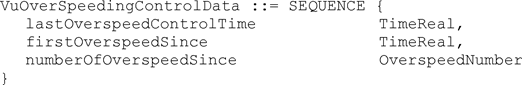
lastOverspeedControlTime is the date and time of the last over speeding control.
firstOverspeedSince is the date and time of the first over speeding following this over speeding control.
numberOfOverspeedSince is the number of over speeding events since the last over speeding control.
2.213.VuOverSpeedingControlDataRecordArrayU.K.
Generation 2:
The VuOverSpeedingControlData plus metadata used in the download protocol.

recordType denotes the type of the record (VuOverSpeedingControlData). Value Assignment: See RecordType
recordSize is the size of the VuOverSpeedingControlData in bytes.
noOfRecords is the number of records in the set records.
records is a set of over speeding control data records.
2.214.VuOverSpeedingEventDataU.K.
Generation 1:
Information, stored in a vehicle unit, related to over speeding events (Annex 1B requirement 094).

noOfVuOverSpeedingEvents is the number of events listed in the vuOverSpeedingEventRecords set.
vuOverSpeedingEventRecords is a set of over speeding events records.
2.215.VuOverSpeedingEventRecordU.K.
Generation 1:
Information, stored in a vehicle unit, related to over speeding events (Annex 1B requirement 094 and Annex 1C requirement 117).
eventType is the type of the event.
eventRecordPurpose is the purpose for which this event has been recorded.
eventBeginTime is the date and time of beginning of event.
eventEndTime is the date and time of end of event.
maxSpeedValue is the maximum speed measured during the event.
averageSpeedValue is the arithmetic average speed measured during the event.
cardNumberDriverSlotBegin identifies the card inserted in the driver slot at the beginning of the event.
similarEventsNumber is the number of similar events that day.
Generation 2:
Information, stored in a vehicle unit, related to over speeding events (Annex 1B requirement 094 and Annex 1C requirement 117).
Instead of cardNumberDriverSlotBegin, the generation 2 data structure makes use of the following data element:
cardNumberAndGenDriverSlotBegin identifies the card including its generation which is inserted in the driver slot at the beginning of the event.


2.216.VuOverSpeedingEventRecordArrayU.K.
Generation 2:
Information, stored in a vehicle unit, related to over speeding events (Annex 1C requirement 117).

recordType denotes the type of the record (VuOverSpeedingEventRecord). Value Assignment: See RecordType
recordSize is the size of the VuOverSpeedingEventRecord in bytes.
noOfRecords is the number of records in the set records.
records is a set of over speeding events records.
2.217.VuPartNumberU.K.
Part number of the vehicle unit.

Value assignment: VU manufacturer specific.
2.218.VuPlaceDailyWorkPeriodDataU.K.
Generation 1:
Information, stored in a vehicle unit, related to places where drivers begin or end a daily work period (Annex 1B requirement 087 and Annex 1C requirement 108 and 110).

noOfPlaceRecords is the number of records listed in the vuPlaceDailyWorkPeriodRecords set.
vuPlaceDailyWorkPeriodRecords is a set of place related records.
2.219.VuPlaceDailyWorkPeriodRecordU.K.
Generation 1:
Information, stored in a vehicle unit, related to a place where a driver begins or ends a daily work period (Annex 1B requirement 087 and Annex 1C requirement 108 and 110).
fullCardNumber is the driver's card type, card issuing Member State and card number.
placeRecord contains the information related to the place entered.
Generation 2:
Information, stored in a vehicle unit, related to a place where a driver begins or ends a daily work period (Annex 1B requirement 087 and Annex 1C requirement 108 and 110).
Instead of fullCardNumber, the generation 2 data structure makes use of the following data element:
fullCardNumberAndGeneration is the type of card, its issuing Member State, its card number and generation as stored in the card.


2.220.VuPlaceDailyWorkPeriodRecordArrayU.K.
Generation 2:
Information, stored in a vehicle unit, related to places where drivers begin or end a daily work period (Annex 1C requirement 108 and 110).

recordType denotes the type of the record (VuPlaceDailyWorkPeriodRecord). Value Assignment: See RecordType
recordSize is the size of the VuPlaceDailyWorkPeriodRecord in bytes.
noOfRecords is the number of records in the set records.
records is a set of place related records.
2.221.VuPrivateKeyU.K.
Generation 1:
The private key of a vehicle unit.

2.222.VuPublicKeyU.K.
Generation 1:
The public key of a vehicle unit.

2.223.VuSerialNumberU.K.
Serial number of the vehicle unit (Annex 1B requirement 075 and Annex 1C requirement 93).

2.224.VuSoftInstallationDateU.K.
Date of installation of the vehicle unit software version.

Value assignment: Unspecified.
2.225.VuSoftwareIdentificationU.K.
Information, stored in a vehicle unit, related to the software installed.

vuSoftwareVersion is the software version number of the Vehicle Unit.
vuSoftInstallationDate is the software version installation date.
2.226.VuSoftwareVersionU.K.
Software version number of the vehicle unit.

Value assignment: Unspecified.
2.227.VuSpecificConditionDataU.K.
Generation 1:
Information, stored in a vehicle unit, related to specific conditions.

noOfSpecificConditionRecords is the number of records listed in the specificConditionRecords set.
specificConditionRecords is a set of specific conditions related records.
2.228.VuSpecificConditionRecordArrayU.K.
Generation 2:
Information, stored in a vehicle unit, related to specific conditions (Annex 1C requirement 130).
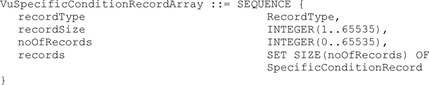
recordType denotes the type of the record (SpecificConditionRecord). Value Assignment: See RecordType
recordSize is the size of the SpecificConditionRecord in bytes.
noOfRecords is the number of records in the set records.
records is a set of specific conditions related records.
2.229.VuTimeAdjustmentDataU.K.
Generation 1:
Information, stored in a vehicle unit, related to time adjustments performed outside the frame of a regular calibration (Annex 1B requirement 101).

noOfVuTimeAdjRecords is the number of records in vuTimeAdjustmentRecords.
vuTimeAdjustmentRecords is a set of time adjustment records.
[F22.230. Reserved for future use U.K.
2.231. Reserved for future use] U.K.
2.232.VuTimeAdjustmentRecordU.K.
Information, stored in a vehicle unit, related a time adjustment performed outside the frame of a regular calibration (Annex 1B requirement 101 and Annex 1C requirement 124 and 125).
Generation 1:
oldTimeValue, newTimeValue are the old and new values of date and time.
workshopName, workshopAddress are the workshop name and address.
workshopCardNumber identifies the workshop card used to perform the time adjustment.
Generation 2:
Instead of workshopCardNumber the generation 2 data structure makes use of the following data element.
workshopCardNumberAndGeneration identifies the workshop card including its generation used to perform the time adjustment.
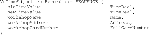

2.233.VuTimeAdjustmentRecordArrayU.K.
Generation 2:
Information, stored in a vehicle unit, related to time adjustments performed outside the frame of a regular calibration (Annex 1C requirement 124 and 125).
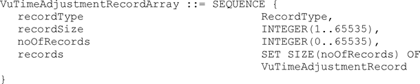
recordType denotes the type of the record (VuTimeAdjustmentRecord). Value Assignment: See RecordType
recordSize is the size of the VuTimeAdjustmentRecord in bytes.
noOfRecords is the number of records in the set records.
records is a set of time adjustment records.
2.234.WorkshopCardApplicationIdentificationU.K.
Information, stored in a workshop card related to the identification of the application of the card (Annex 1C requirement 307 and 330).
Generation 1:
typeOfTachographCardId is specifying the implemented type of card.
cardStructureVersion is specifying the the version of the structure that is implemented in the card.
noOfEventsPerType is the number of events per type of event the card can record.
noOfFaultsPerType is the number of faults per type of fault the card can record.
activityStructureLength indicates the number of bytes available for storing activity records.
noOfCardVehicleRecords is the number of vehicle records the card can contain.
noOfCardPlaceRecords is the number of places the card can record.
noOfCalibrationRecords is the number of calibration records the card can store.
Generation 2:
[F2In addition to generation 1 the following data elements are used:
noOfGNSSADRecords is the number of GNSS accumulated driving records the card can store.
noOfSpecificConditionRecords is the number of specific condition records the card can store.
noOfCardVehicleUnitRecords is the number of vehicle units used records the card can store.]
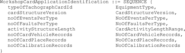

2.235.WorkshopCardCalibrationDataU.K.
Information, stored in a workshop card, related to workshop activity performed with the card (Annex 1C requirements 314, 316, 337, and 339).

calibrationTotalNumber is the total number of calibrations performed with the card.
calibrationPointerNewestRecord is the index of the last updated calibration record.
Value assignment: Number corresponding to the numerator of the calibration record, beginning with ‘0’ for the first occurrence of the calibration records in the structure.
calibrationRecords is the set of records containing calibration and/or time adjustment information.
2.236.WorkshopCardCalibrationRecordU.K.
Information, stored in a workshop card, related to a calibration performed with the card (Annex 1C requirement 314 and 337).
Generation 1:
calibrationPurpose is the purpose of the calibration.
vehicleIdentificationNumber is the VIN.
vehicleRegistration contains the VRN and registering Member State.
wVehicleCharacteristicConstant is the characteristic coefficient of the vehicle.
kConstantOfRecordingEquipment is the constant of the recording equipment.
lTyreCircumference is the effective circumference of the wheel tyres.
tyreSize is the designation of the dimensions of the tyres mounted on the vehicle.
authorisedSpeed is the maximum authorised speed of the vehicle.
oldOdometerValue, newOdometerValue are the old and new values of the odometer.
oldTimeValue, newTimeValue are the old and new values of date and time.
nextCalibrationDate is the date of the next calibration of the type specified in CalibrationPurpose to be carried out by the authorised inspection authority.
vuPartNumber, vuSerialNumber and sensorSerialNumber are the data elements for recording equipment identification.
Generation 2:
In addition to generation 1 the following data elements are used:
sensorGNSSSerialNumber which identifies an external GNSS facility.
rcmSerialNumber which identifies a Remote Communication Module.
sealDataCard gives information about the seals that are attached to different components of the vehicle.


2.237.WorkshopCardHolderIdentificationU.K.
Information, stored in a workshop card, related to the identification of the cardholder (Annex 1C requirement 311 and 334).

workshopName is name of the workshop of the card holder.
workshopAddress is the address of the workshop of the card holder.
cardHolderName is the name and first name(s) of the holder (e.g. the name of the mechanic).
cardHolderPreferredLanguage is the preferred language of the card holder.
2.238.WorkshopCardPINU.K.
Personal identification number of the Workshop Card (Annex 1C requirement 309 and 332).

Value assignment: The PIN known to the cardholder, right padded with ‘FF’ bytes up to 8 bytes.
2.239.W-VehicleCharacteristicConstantU.K.
Characteristic coefficient of the vehicle (definition k)).

Value assignment: Impulses per kilometer in the operating range 0 to 64 255 pulses/km.
2.240.VuPowerSupplyInterruptionRecordU.K.
Generation 2:
Information, stored in a vehicle unit, related to Power Supply Interruption events (Annex 1C requirement 117).

eventType is the type of the event.
eventRecordPurpose is the purpose for which this event has been recorded.
eventBeginTime is the date and time of beginning of event.
eventEndTime is the date and time of end of event.
cardNumberAndGenDriverSlotBegin identifies the card including its generation inserted in the driver slot at the beginning of the event.
cardNumberAndGenDriverSlotEnd identifies the card including its generation inserted in the driver slot at the end of the event.
cardNumberAndGenCodriverSlotBegin identifies the card including its generation inserted in the co-driver slot at the beginning of the event.
cardNumberAndGenCodriverSlotEnd identifies the card including its generation inserted in the co-driver slot at the end of the event.
similarEventsNumber is the number of similar events that day.
2.241.VuPowerSupplyInterruptionRecordArrayU.K.
Generation 2:
Information, stored in a vehicle unit, related to Power Supply Interruption events (Annex 1C requirement 117).

recordType denotes the type of the record (VuPowerSupplyInterruptionRecord). Value Assignment: See RecordType
recordSize is the size of the VuPowerSupplyInterruptionRecord in bytes.
noOfRecords is the number of records in the set records.
records is a set of power supply interruption events records.
2.242.VuSensorExternalGNSSCoupledRecordArrayU.K.
Generation 2:
A set of SensorExternalGNSSCoupledRecord plus metadata used in the download protocol.

recordType denotes the type of the record (SensorExternalGNSSCoupledRecord). Value Assignment: See RecordType
recordSize is the size of the SensorExternalGNSSCoupledRecord in bytes.
noOfRecords is the number of records in the set records.
records is a set of Sensor External GNSS Coupled records.
2.243.VuSensorPairedRecordArrayU.K.
Generation 2:
A set of SensorPairedRecord plus metadata used in the download protocol.

recordType denotes the type of the record (SensorPairedRecord). Value Assignment: See RecordType
recordSize is the size of the SensorPairedRecord in bytes.
noOfRecords is the number of records in the set records.
records is a set of sensor paired records.
3.VALUE AND SIZE RANGE DEFINITIONSU.K.
Definition of variable values used for definitions in paragraph 2.

4.CHARACTER SETSU.K.
IA5Strings use the ASCII characters as defined by ISO/IEC 8824-1. For readability and for easy referencing the value assignment is given below. The ISO/IEC 8824-1 supersedes this informative note in case of discrepancy.

| Other character strings (Address, Name, VehicleRegistrationNumber) use, in addition, characters from the decimal character code range 161 — 255 of the following 8-bit, standard character sets, specified by the Code Page number:Standard Character Set | Code Page(Decimal) |
|---|---|
| ISO/IEC 8859-1 Latin-1 Western European | 1 |
| ISO/IEC 8859-2 Latin-2 Central European | 2 |
| ISO/IEC 8859-3 Latin-3 South European | 3 |
| ISO/IEC 8859-5 Latin / Cyrillic | 5 |
| ISO/IEC 8859-7 Latin / Greek | 7 |
| ISO/IEC 8859-9 Latin-5 Turkish | 9 |
| ISO/IEC 8859-13 Latin-7 Baltic Rim | 13 |
| ISO/IEC 8859-15 Latin-9 | 15 |
| ISO/IEC 8859-16 Latin-10 South Eastern European | 16 |
| KOI8-R Latin / Cyrillic | 80 |
| KOI8-U Latin / Cyrillic | 85 |
5.ENCODINGU.K.
When encoded with ASN.1 encoding rules, all data types defined shall be encoded according to ISO/IEC 8825-2, aligned variant.
6.OBJECT IDENTIFIERS UND APPLICATION IDENTIFIERSU.K.
6.1.Object IdentifiersU.K.
The Object Identifiers (OIDs) listed in this chapter are only relevant for generation 2. These OIDs are specified in TR-03110-3 and repeated here for the sake of completeness. These OIDs are contained in the subtree of bsi-de:

VU Authentication protocol identifiersU.K.

Example: Suppose VU Authentication is to be done with SHA-384, then the object identifier to use is (in ASN.1 notation) 

| Dot notation | Byte notation | |
|---|---|---|
 |  | ‘04 00 7F 00 07 02 02 02 02 03’ |
 |  | ‘04 00 7F 00 07 02 02 02 02 04’ |
 |  | ‘04 00 7F 00 07 02 02 02 02 05’ |
Chip Authentication protocol identifiersU.K.

Example: Suppose Chip Authentication is to be done by using the ECDH algorithm, resulting in an AES session key length of 128 bits. This session key will subsequently be used in the CBC mode of operation to ensure data confidentiality and with the CMAC algorithm to ensure data authenticity. Therefore, the object identifier to use is (in ASN.1 notation) 

| Dot notation | Byte notation | |
|---|---|---|
 |  | ‘04 00 7F 00 07 02 02 03 02 02’ |
 |  | ‘04 00 7F 00 07 02 02 03 02 03’ |
 |  | ‘04 00 7F 00 07 02 02 03 02 04’ |
6.2.Application IdentifiersU.K.
Generation 2:
The Application Identifier (AID) for the External GNSS Facility (Generation 2) is given by ‘FF 44 54 45 47 4D’. This is a proprietary AID according to ISO/IEC 7816-4.
Note: The last 5 bytes encode DTEGM for smart Tachograph External GNSS Facility.U.K.
The Application Identifier for the generation 2 tachograph card application is given by ‘FF 53 4D 52 44 54’. This is a proprietary AID according to ISO/IEC 7816-4.
Appendix 2
TACHOGRAPH CARDS SPECIFICATIONU.K.
1.INTRODUCTIONU.K.
1.1.AbbreviationsU.K.
For the purpose of this appendix, the following abbreviations apply.
AC
Access conditions
AES
Advanced Encryption Standard
AID
Application Identifier
ALW
Always
APDU
Application Protocol Data Unit (structure of a command)
ATR
Answer To Reset
AUT
Authenticated.
C6, C7
Contacts No 6 and 7 of the card as described in ISO/IEC 7816-2
cc
clock cycles
Certificate Holder Authorisation]
CHV
Card holder Verification Information
CLA
Class byte of an APDU command
Data Object]
DSRC
Dedicated Short Range Communication
DF
Dedicated File. A DF can contain other files (EF or DF)
ECC
Elliptic Curve Cryptography
EF
Elementary File
etu
elementary time unit
G1
Generation 1
G2
Generation 2
IC
Integrated Circuit
ICC
Integrated Circuit Card
ID
Identifier
IFD
Interface Device
IFS
Information Field Size
IFSC
Information Field Size for the card
IFSD
Information Field Size Device (for the Terminal)
INS
Instruction byte of an APDU command
Lc
Length of the input data for a APDU command
Le
Length of the expected data (output data for a command)
MF
Master File (root DF)
NAD
Node Address used in T=1 protocol
NEV
Never
P1-P2
Parameter bytes
PIN
Personal Identification Number
PRO SM
Protected with secure messaging
PTS
Protocol Transmission Selection
RFU
Reserved for Future Use
RST
Reset (of the card)
SFID
Short EF Identifier
SM
Secure Messaging
SW1-SW2
Status bytes
TS
Initial ATR character
VPP
Programming Voltage
VU
Vehicle Unit
XXh
Value XX in hexadecimal notation
‘XXh’
Value XX in hexadecimal notation
||
Concatenation symbol 03||04=0304
1.2.ReferencesU.K.
The following references are used in this Appendix:
ISO/IEC 7816-2
Identification cards — Integrated circuit cards — Part 2: Dimensions and location of the contacts. ISO/IEC 7816-2:2007.
ISO/IEC 7816-3
Identification cards — Integrated circuit cards — Part 3: Electrical interface and transmission protocols. ISO/IEC 7816-3:2006.
ISO/IEC 7816-4
Identification cards — Integrated circuit cards — Part 4: Organization, security and commands for interchange. ISO/IEC 7816-4:2013 + Cor 1: 2014.
ISO/IEC 7816-6
Identification cards — Integrated circuit cards — Part 6: Interindustry data elements for interchange. ISO/IEC 7816-6:2004 + Cor 1: 2006.
ISO/IEC 7816-8
Identification cards — Integrated circuit cards — Part 8: Commands for security operations. ISO/IEC 7816-8:2004.
ISO/IEC 9797-2
Information technology — Security techniques — Message Authentication Codes (MACs) — Part 2: Mechanisms using a dedicated hash-function. ISO/IEC 9797-2:2011
2.ELECTRICAL AND PHYSICAL CHARACTERISTICSU.K.
TCS_01All electronic signals shall be in accordance with ISO/IEC 7816-3 unless specified otherwise.U.K.
TCS_02The location and dimensions of the card contacts shall comply with the ISO/IEC 7816-2.U.K.
2.1.Supply Voltage and Current ConsumptionU.K.
TCS_03The card shall work according to specifications within the consumption limits specified in ISO/IEC 7816-3.U.K.
TCS_04The card shall work with Vcc = 3V (± 0,3V) or with Vcc = 5V (± 0,5V).U.K.
Voltage selection shall be performed according to ISO/IEC 7816-3.
2.2.Programming Voltage Vpp U.K.
TCS_05The card shall not require a programming voltage at pin C6. It is expected that pin C6 is not connected in an IFD. Contact C6 may be connected to Vcc in the card but shall not be connected to ground. This voltage should not be interpreted in any case.U.K.
2.3.Clock generation and FrequencyU.K.
TCS_06The card shall operate within a frequency range of 1 to 5 MHz and may support higher frequencies. Within one card session the clock frequency may vary ± 2 %. The clock frequency is generated by the Vehicle Unit and not the card itself. The duty cycle may vary between 40 and 60 %.U.K.
TCS_07Under conditions contained into the card file EF ICC, the external clock can be stopped. The first byte of the EF ICC file body codes the Clockstop mode conditions:U.K.
| Low | High | ||
|---|---|---|---|
| Bit 3 | Bit 2 | Bit 1 | |
| 0 | 0 | 1 | Clockstop allowed, no preferred level |
| 0 | 1 | 1 | Clockstop allowed, high level preferred |
| 1 | 0 | 1 | Clockstop allowed, low level preferred |
| 0 | 0 | 0 | Clockstop not allowed |
| 0 | 1 | 0 | Clockstop only allowed on high level |
| 1 | 0 | 0 | Clockstop only allowed on low level |
Bits 4 to 8 are not used.
2.4.I/O ContactU.K.
TCS_08The I/O contact C7 is used to receive data from and to transmit data to the IFD. During operation only either the card or the IFD shall be in transmit mode. Should both units be in transmit mode no damage shall occur to the card. Unless transmitting, the card shall enter the reception mode.U.K.
2.5.States of the CardU.K.
TCS_09The card works in two states while the supply voltage is applied:U.K.
Operation state while executing commands or interfacing with Digital Unit,
Idle state at all other times; in this state all data shall be retained by the card.
3.HARDWARE AND COMMUNICATIONU.K.
3.1.IntroductionU.K.
This paragraph describes the minimum functionality required by Tachograph cards and VUs to ensure correct operation and interoperability.
Tachograph cards are as compliant as possible with the available ISO/IEC applicable norms (especially ISO/IEC 7816). However, commands and protocols are fully described in order to specify some restricted usage or some differences if they exist. The commands specified are fully compliant with the referred norms except where indicated.
3.2.Transmission ProtocolU.K.
TCS_10The Transmission protocol shall be compliant with ISO/IEC 7816-3 for T = 0 and T = 1. In particular, the VU shall recognise waiting time extensions sent by the card.U.K.
3.2.1ProtocolsU.K.
TCS_11The card shall provide both protocol T=0 and protocol T=1. In addition the card may support further contact-oriented protocols.U.K.
TCS_12T=0 is the default protocol, a PTS command is therefore necessary to change the protocol to T=1.U.K.
TCS_13Devices shall support direct convention in both protocols: the direct convention is hence mandatory for the card.U.K.
TCS_14The Information Field Size Card byte shall be presented at the ATR in character TA3. This value shall be at least ‘F0h’ (=240 bytes).U.K.
The following restrictions apply to the protocols:
TCS_15T=0U.K.
The interface device shall support an answer on I/O after the rising edge of the signal on RST from 400 cc.
The interface device shall be able to read characters separated with 12 etu.
The interface device shall read an erroneous character and its repetition if separated with 13 etu. If an erroneous character is detected, the Error signal on I/O can occur between 1 etu and 2 etu. The device shall support a 1 etu delay.
The interface device shall accept a 33 bytes ATR (TS+32)
If TC1 is present in the ATR, the Extra Guard Time shall be present for characters sent by the interface device although characters sent by the card can still be separated with 12 etu. This is also true for the ACK character sent by the card after a P3 character emitted by the interface device.
The interface device shall take into account a NUL character emitted by the card.
The interface device shall accept the complementary mode for ACK.
The get-response command cannot be used in chaining mode to get a data which length could exceed 255 bytes.
TCS_16T=1U.K.
NAD byte: not used (NAD shall be set to ‘00’).
S-block ABORT: not used.
S-block VPP state error: not used.
The total chaining length for a data field will not exceed 255 bytes (to be ensured by the IFD).
The Information Field Size Device (IFSD) shall be indicated by the IFD immediately after the ATR: the IFD shall transmit the S-Block IFS request after the ATR and the card shall send back S-Block IFS. The recommended value for IFSD is 254 bytes.
The card will not ask for an IFS readjustment.
3.2.2ATRU.K.
TCS_17The device checks ATR bytes, according to ISO/IEC 7816-3. No verification shall be done on ATR Historical Characters.U.K.
Example of Basic Biprotocol ATR according to ISO/IEC 7816-3
| Character | Value | Remarks |
|---|---|---|
| TS | ‘3Bh’ | Indicates direct convention. |
| T0 | ‘85h’ | TD1 present; 5 historical bytes are presents. |
| TD1 | ‘80h’ | TD2 present; T=0 to be used |
| TD2 | ‘11h’ | TA3 present; T=1 to be used |
| TA3 | ‘XXh’ (at least ‘F0h’) | Information Field Size Card ( IFSC) |
| TH1 to TH5 | ‘XXh’ | Historical characters |
| TCK | ‘XXh’ | Check Character (exclusive OR) |
TCS_18After the Answer To Reset (ATR), the Master File (MF) is implicitly selected and becomes the Current Directory.U.K.
3.2.3PTSU.K.
TCS_19The default Protocol is T=0. To set the T=1 protocol, a PTS (also known as PPS) must be sent to the card by the device.U.K.
TCS_20As both T=0 and T=1 protocols are mandatory for the card, the basic PTS for protocol switching is mandatory for the card.U.K.
The PTS can be used, as indicated in ISO/IEC 7816-3, to switch to higher baud rates than the default one proposed by the card in the ATR if any (TA(1) byte).
Higher baud rates are optional for the card.
TCS_21If no other baud rate than the default one are supported (or if the selected baud rate is not supported), the card shall respond to the PTS correctly according to ISO/IEC 7816-3 by omitting the PPS1 byte.U.K.
Examples of basic PTS for protocol selection are the following:
| Character | Value | Remarks |
|---|---|---|
| PPSS | ‘FFh’ | The Initiate Character. |
| PPS0 | ‘00h’ or ‘01h’ | PPS1 to PPS3 are not present; ‘00h’ to select T0, ‘01h’ to select T1. |
| PK | ‘XXh’ | Check Character : ‘XXh’ = ‘FFh’ if PPS0 = ‘00h’, ‘XXh’ = ‘FEh’ if PPS0 = ‘01h’. |
3.3.Access RulesU.K.
TCS_22An access rule specifies for an access mode, i.e. command, the corresponding security conditions. If these security conditions are fulfilled the corresponding command is processed.U.K.
TCS_23The following security conditions are used for the tachograph card:U.K.
| Abbreviation | Meaning |
|---|---|
| ALW | The action is always possible and can be executed without any restriction. Command and response APDU are sent in plain text, i.e. without secure messaging. |
| NEV | The action is never possible. |
| PLAIN-C | The command APDU is sent in plain, i.e. without secure messaging. |
| PWD | The action may only be executed if the workshop card PIN has been successfully verified, i.e. if the card internal security status ‘PIN_Verified’ is set. The command must be sent without secure messaging. |
| EXT-AUT-G1 | The action may only be executed if the External Authenticate command for the generation 1 authentication (see also Appendix 11 Part A) has been successfully performed. |
| SM-MAC-G1 | The APDU (command and response) must be applied with generation 1 secure messaging in authentication-only mode (see Appendix 11 Part A). |
| SM-C-MAC-G1 | The command APDU must be applied with generation 1 secure messaging in authentication only mode (see Appendix 11 Part A). |
| SM-R-ENC-G1 | The response APDU must be applied with generation 1 secure messaging in encryption mode (see Appendix 11 Part A), i.e. no message authentication code is returned. |
| SM-R-ENC-MAC-G1 | The response APDU must be applied with generation 1 secure messaging in encrypt-then-authenticate mode (see Appendix 11 Part A). |
| SM-MAC-G2 | The APDU (command and response) must be applied with generation 2 secure messaging in authentication-only mode (see Appendix 11 Part B). |
| SM-C-MAC-G2 | The command APDU must be applied with generation 2 secure messaging in authentication only mode (see Appendix 11 Part B). |
| SM-R-ENC-MAC-G2 | The response APDU must be applied with generation 2 secure messaging in encrypt-then-authenticate mode (see Appendix 11 Part B). |
[F2TCS_24 These security conditions can be linked in the following ways: U.K.
AND
:
All security conditions must be fulfilled
OR
:
At least one security condition must be fulfilled
The access rules for the file system, i.e. the SELECT, READ BINARY and UPDATE BINARY command, are specified in chapter 4. The access rules for the remaining commands are specified in the following tables. The term ‘not applicable’ is used if there is no requirement to support the command. In this case the command may or may not be supported, but the access condition is out of scope.]
TCS_25In the DF Tachograph G1 application the following access rules are used:U.K.
| [F2Command | Driver Card | Workshop Card | Control Card | Company Card |
|---|---|---|---|---|
| External Authenticate | ||||
— For generation 1 authentication | ALW | ALW | ALW | ALW |
— For generation 2 authentication | ALW | PWD | ALW | ALW |
| Internal Authenticate | ALW | PWD | ALW | ALW |
| General Authenticate | ALW | ALW | ALW | ALW |
| Get Challenge | ALW | ALW | ALW | ALW |
| MSE:SET AT | ALW | ALW | ALW | ALW |
| MSE:SET DST | ALW | ALW | ALW | ALW |
| Process DSRC Message | Not applicable | Not applicable | Not applicable | Not applicable |
| PSO: Compute Digital Signature | ALW OR SM-MAC-G2 | ALW OR SM-MAC-G2 | Not applicable | Not applicable |
| PSO: Hash | Not applicable | Not applicable | ALW | Not applicable |
| PERFORM HASH of FILE | ALW OR SM-MAC-G2 | ALW OR SM-MAC-G2 | Not applicable | Not applicable |
| PSO: Verify Certificate | ALW | ALW | ALW | ALW |
| PSO: Verify Digital Signature | Not applicable | Not applicable | ALW | Not applicable |
| Verify | Not applicable | ALW | Not applicable | Not applicable] |
TCS_26In the DF Tachograph_G2 application the following access rules are used:U.K.
| [F2Command | Driver Card | Workshop Card | Control Card | Company Card |
|---|---|---|---|---|
| External Authenticate | ||||
— For generation 1 authentication | Not applicable | Not applicable | Not applicable | Not applicable |
— For generation 2 authentication | ALW | PWD | ALW | ALW |
| Internal Authenticate | Not applicable | Not applicable | Not applicable | Not applicable |
| General Authenticate | ALW | ALW | ALW | ALW |
| Get Challenge | ALW | ALW | ALW | ALW |
| MSE:SET AT | ALW | ALW | ALW | ALW |
| MSE:SET DST | ALW | ALW | ALW | ALW |
| Process DSRC Message | Not applicable | ALW | ALW | Not applicable |
| PSO: Compute Digital Signature | ALW OR SM-MAC-G2 | ALW OR SM-MAC-G2 | Not applicable | Not applicable |
| PSO: Hash | Not applicable | Not applicable | ALW | Not applicable |
| PERFORM HASH of FILE | ALW OR SM-MAC-G2 | ALW OR SM-MAC-G2 | Not applicable | Not applicable |
| PSO: Verify Certificate | ALW | ALW | ALW | ALW |
| PSO: Verify Digital Signature | Not applicable | Not applicable | ALW | Not applicable |
| Verify | Not applicable | ALW | Not applicable | Not applicable] |
TCS_27In the MF the following access rules are used:U.K.
| [F2Command | Driver Card | Workshop Card | Control Card | Company Card |
|---|---|---|---|---|
| External Authenticate | ||||
— For generation 1 authentication | Not applicable | Not applicable | Not applicable | Not applicable |
— For generation 2 authentication | ALW | PWD | ALW | ALW |
| Internal Authenticate | Not applicable | Not applicable | Not applicable | Not applicable |
| General Authenticate | ALW | ALW | ALW | ALW |
| Get Challenge | ALW | ALW | ALW | ALW |
| MSE:SET AT | ALW | ALW | ALW | ALW |
| MSE:SET DST | ALW | ALW | ALW | ALW |
| Process DSRC Message | Not applicable | Not applicable | Not applicable | Not applicable |
| PSO: Compute Digital Signature | Not applicable | Not applicable | Not applicable | Not applicable |
| PSO: Hash | Not applicable | Not applicable | Not applicable | Not applicable |
| PERFORM HASH of FILE | Not applicable | Not applicable | Not applicable | Not applicable |
| PSO: Verify Certificate | ALW | ALW | ALW | ALW |
| PSO: Verify Digital Signature | Not applicable | Not applicable | Not applicable | Not applicable |
| Verify | Not applicable | ALW | Not applicable | Not applicable] |
TCS_28A tachograph card may or may not accept a command with a higher level of security than the one specified in the security conditions. I.e. if the security condition is ALW (or PLAIN-C) the card may accept a command with secure messaging (encryption and / or authentication mode). If the security condition requires secure messaging with authentication mode, the tachograph card may accept a command with secure messaging of the same generation in authentication and encryption mode.U.K.
Note: The command descriptions provide more information on the support of the commands for the different tachograph card types and the different DFs.U.K.
3.4.Commands and error codes overviewU.K.
Commands and file organisation are deduced from and complies with ISO/IEC 7816-4.
This section describes the following APDU command-response pairs. The command variants which are supported by a generation 1 and 2 application are specified in the corresponding command descriptions.
[F2TCS_29 The status words SW1 SW2 are returned in any response message and denote the processing state of the command. U.K.
Additional status words as defined in ISO/IEC 7816-4 can be returned, if their behaviour is not explicitly mentioned in this appendix.
For example the following status words can be optionally returned:
6881: Logical channel not supported
6882: Secure messaging not supported]
TCS_30If more than one error condition is fulfilled in one command APDU the card may return any of the appropriate status words.U.K.
3.5.Command descriptionsU.K.
The mandatory commands for the Tachograph cards are described in this chapter.
Additional relevant details, related to cryptographic operations involved, are given in Appendix 11 Common security mechanisms for Tachograph Generation 1 and Generation 2.
All commands are described independently of the used protocol (T=0 or T=1). The APDU bytes CLA, INS, P1, P2, Lc and Le are always indicated. If Lc or Le is not needed for the described command, the associated length, value and description are empty.
TCS_31If both length bytes (Lc and Le) are requested, the described command has to be split in two parts if the IFD is using protocol T=0: the IFD sends the command as described with P3=Lc + data and then sends a GET RESPONSE (see § 3.5.6) command with P3=Le.U.K.
TCS_32If both length bytes are requested, and Le=0 (secure messaging):U.K.
When using protocol T=1, the card shall answer to Le=0 by sending all available output data.
When using protocol T=0, the IFD shall send the first command with P3=Lc + data, the card shall answer (to this implicit Le=0) by the Status bytes ‘61La’, where La is the number of response bytes available. The IFD shall then generate a GET RESPONSE command with P3 = La to read the data.
TCS_33A tachograph card may support extended length fields according to ISO/IEC 7816-4 as an optional feature. A tachograph card that supports extended length fields shallU.K.
Indicate the extended length field support in the ATR
Provide the supported buffer sizes by means of the extended length information in the EF ATR/INFO see TCS_146.
Indicate whether it supports extended length fields for T = 1 and / or T = 0 in the EF Extended Length, see TCS_147.
Support extended length fields for the tachograph application generation 1 and 2.
Notes:U.K.
All commands are specified for short length fields. The usage of extended length APDUs is clear from ISO/IEC 7816-4.U.K.
In general the commands are specified for the plain mode, i.e. without secure messaging, as the secure messaging layer is specified in Appendix 11. It is clear from the access rules for a command whether the command shall support secure messaging or not and whether the command shall support generation 1 and / or generation 2 secure messaging. Some command variants are described with secure messaging to illustrate the usage of secure messaging.U.K.
TCS_34The VU shall perform the complete generation 2 VU — card mutual authentication protocol for a session including the certificate verification (if required) either in the DF Tachograph, the DF Tachograph_G2 or the MF.U.K.
3.5.1SELECTU.K.
This command is compliant with ISO/IEC 7816-4, but has a restricted usage compared to the command defined in the norm.
The SELECT command is used:
to select an application DF (selection by name must be used)
to select an elementary file corresponding to the submitted file ID
3.5.1.1Selection by name (AID)U.K.
This command allows selecting an application DF in the card.
TCS_35This command can be performed from anywhere in the file structure (after the ATR or at any time).U.K.
TCS_36The selection of an application resets the current security environment. After performing the application selection, no current public key is selected anymore. The EXT-AUT-G1 access condition is also lost. If the command was performed without secure messaging, the former secure messaging session keys are no longer available.U.K.
TCS_37Command MessageU.K.
| Byte | Length | Value | Description |
|---|---|---|---|
| CLA | 1 | ‘00h’ | |
| INS | 1 | ‘A4h’ | |
| P1 | 1 | ‘04h’ | Selection by name (AID) |
| P2 | 1 | ‘0Ch’ | No response expected |
| Lc | 1 | ‘NNh’ | Number of bytes sent to the card (length of the AID): ‘06h’ for the Tachograph application |
| #6-#(5+NN) | NN | ‘XX..XXh’ | AID: ‘FF 54 41 43 48 4F’ for the Generation 1 tachograph application AID: ‘FF 53 4D 52 44 54’ for the Generation 2 tachograph application |
No response to the SELECT command is needed (Le absent in T=1, or no response asked in T=0).
TCS_38Response Message (no response asked)U.K.
| Byte | Length | Value | Description |
|---|---|---|---|
| SW | 2 | ‘XXXXh’ | Status Words (SW1,SW2) |
If the command is successful, the card returns ‘9000’.
If the application corresponding with the AID is not found, the processing state returned is ‘6A82’.
In T=1, if the byte Le is present, the state returned is ‘6700’.
In T=0, if a response is asked after the SELECT command, the state returned is ‘6900’.
[F2If the selected application is considered to be corrupted (integrity error is detected within the file attributes), the processing state returned is ‘ 6400 ’ or ‘ 6500 ’.]
3.5.1.2Selection of an Elementary File using its File IdentifierU.K.
TCS_39Command MessageU.K.
TCS_40A tachograph card shall support the generation 2 secure messaging as specified in Appendix 11 Part B for this command variant.U.K.
| Byte | Length | Value | Description |
|---|---|---|---|
| CLA | 1 | ‘00h’ | |
| INS | 1 | ‘A4h’ | |
| P1 | 1 | ‘02h’ | Selection of an EF under the current DF |
| P2 | 1 | ‘0Ch’ | No response expected |
| Lc | 1 | ‘02h’ | Number of bytes sent to the card |
| #6-#7 | 2 | ‘XXXXh’ | File Identifier |
No response to the SELECT command is needed (Le absent in T=1, or no response asked in T=0).
TCS_41Response Message (no response asked)U.K.
| Byte | Length | Value | Description |
|---|---|---|---|
| SW | 2 | ‘XXXXh’ | Status Words (SW1,SW2) |
If the command is successful, the card returns ‘9000’.
If the file corresponding with the file identifier is not found, the processing state returned is ‘6A82’.
In T=1, if the byte Le is present, the state returned is ‘6700’.
In T=0, if a response is asked after the SELECT command, the state returned is ‘6900’.
[F2If the selected file is considered to be corrupted (integrity error is detected within the file attributes), the processing state returned is ‘ 6400 ’ or ‘ 6500 ’.]
3.5.2READ BINARYU.K.
This command is compliant with ISO/IEC 7816-4, but has a restricted usage compared to the command defined in the norm.
The READ BINARY command is used to read data from a transparent file.
The response of the card consists of returning the data read, optionally encapsulated in a secure messaging structure.
3.5.2.1Command with offset in P1-P2U.K.
This command enables the IFD to read data from the EF currently selected, without secure messaging.
Note: This command without secure messaging can only be used to read a file that supports the ALW security condition for the Read access mode.U.K.
TCS_42Command MessageU.K.
| Byte | Length | Value | Description |
|---|---|---|---|
| CLA | 1 | ‘00h’ | |
| INS | 1 | ‘B0h’ | Read Binary |
| P1 | 1 | ‘XXh’ | Offset in bytes from the beginning of the file: Most Significant Byte |
| P2 | 1 | ‘XXh’ | Offset in bytes from the beginning of the file: Least Significant Byte |
| Le | 1 | ‘XXh’ | Length of data expected. Number of Bytes to be read. |
Note: bit 8 of P1 must be set to 0.U.K.
TCS_43Response MessageU.K.
| Byte | Length | Value | Description |
|---|---|---|---|
| #1-#X | X | ‘XX..XXh’ | Data read |
| SW | 2 | ‘XXXXh’ | Status Words (SW1,SW2) |
If the command is successful, the card returns ‘9000’.
If no EF is selected, the processing state returned is ‘6986’.
If the security conditions of the selected file are not satisfied, the command is interrupted with ‘6982’.
If the Offset is not compatible with the size of the EF (Offset > EF size), the processing state returned is ‘6B00’.
If the size of the data to be read is not compatible with the size of the EF (Offset + Le > EF size) the processing state returned is ‘6700’ or ‘6Cxx’ where ‘xx’ indicates the exact length.
[F2If an integrity error is detected within the file attributes, the card shall consider the file as corrupted and unrecoverable, the processing state returned is ‘ 6400 ’ or ‘ 6500 ’.]
If an integrity error is detected within the stored data, the card shall return the demanded data, and the processing state returned is ‘6281’.
3.5.2.1.1Command with secure messaging (examples)U.K.
This command enables the IFD to read data from the EF currently selected with secure messaging, in order to verify the integrity of the data received and to protect the confidentiality of the data if the security condition SM-R-ENC-MAC-G1 (generation 1) or SM-R-ENC-MAC-G2 (generation 2) is applied.
TCS_44Command MessageU.K.
| Byte | Length | Value | Description |
|---|---|---|---|
| CLA | 1 | ‘0Ch’ | Secure Messaging asked |
| INS | 1 | ‘B0h’ | Read Binary |
| P1 | 1 | ‘XXh’ | P1 ( offset in bytes from the beginning of the file): Most Significant Byte |
| P2 | 1 | ‘XXh’ | P2 ( offset in bytes from the beginning of the file): Least Significant Byte |
| Lc | 1 | ‘XXh’ | Length of input data for secure messaging |
| #6 | 1 | ‘97h’ | TLE: Tag for expected length specification. |
| #7 | 1 | ‘01h’ | LLE: Length of expected length |
| #8 | 1 | ‘NNh’ | Expected length specification (original Le): Number of Bytes to be read |
| #9 | 1 | ‘8Eh’ | TCC: Tag for cryptographic checksum |
| #10 | 1 | ‘XXh’ | LCC: Length of following cryptographic checksum
|
| #11-#(10+L) | L | ‘XX..XXh’ | Cryptographic checksum |
| Le | 1 | ‘00h’ | As specified in ISO/IEC 7816-4 |
TCS_45Response Message if SM-R-ENC-MAC-G1 (generation 1) / SM-R-ENC-MAC-G2 (generation 2) is not required and if Secure Messaging input format is correct:U.K.
| [F2Byte | Length | Value | Description |
|---|---|---|---|
| #1 | 1 | ‘ 81h ’ | T PV : Tag for plain value data |
| #2 | L | ‘NNh’ or ‘81 NNh’ | L PV : length of returned data (=original Le). L is 2 bytes if L PV >127 bytes. |
| #(2+L) - #(1+L+NN) | NN | ‘ XX..XXh ’ | Plain Data value |
| #(2+L+NN) | 1 | ‘ 99h ’ | Tag for Processing Status (SW1-SW2) – optional for generation 1 secure messaging |
| #(3+L+NN) | 1 | ‘ 02h ’ | Length of Processing Status – optional for generation 1 secure messaging |
| #(4+L+NN) - #(5+L+NN) | 2 | ‘ XX XXh ’ | Processing Status of the unprotected response APDU – optional for generation 1 secure messaging |
| #(6+L+NN) | 1 | ‘ 8Eh ’ | TCC: Tag for cryptographic checksum |
| #(7+L+NN) | 1 | ‘ XXh ’ | LCC: Length of following cryptographic checksum
|
| #(8+L+NN)-#(7+M+L+NN) | M | ‘ XX..XXh ’ | Cryptographic checksum |
| SW | 2 | ‘ XXXXh ’ | Status Words (SW1,SW2)] |
TCS_46Response Message if SM-R-ENC-MAC-G1 (generation 1) / SM-R-ENC-MAC-G2 (generation 2) is required and if Secure Messaging input format is correct:U.K.
| [F2Byte | Length | Value | Description |
|---|---|---|---|
| #1 | 1 | ‘ 87h ’ | T PI CG : Tag for encrypted data (cryptogram) |
| #2 | L | ‘MMh’ or ‘81 MMh’ | L PI CG : length of returned encrypted data (different of original Le of the command due to padding). L is 2 bytes if LPI CG > 127 bytes. |
| #(2+L)-#(1+L+MM) | MM | ‘ 01XX..XXh ’ | Encrypted Data: Padding Indicator and cryptogram |
| #(2+L+MM) | 1 | ‘ 99h ’ | Tag for Processing Status (SW1-SW2) – optional for generation 1 secure messaging |
| #(3+L+MM) | 1 | ‘ 02h ’ | Length of Processing Status – optional for generation 1 secure messaging |
| #(4+L+MM) - #(5+L+MM) | 2 | ‘ XX XXh ’ | Processing Status of the unprotected response APDU – optional for generation 1 secure messaging |
| #(6+L+MM) | 1 | ‘ 8Eh ’ | TCC: Tag for cryptographic checksum |
| #(7+L+MM) | 1 | ‘ XXh ’ | LCC: Length of following cryptographic checksum
|
| #(8+L+MM)-#(7+N+L+MM) | N | ‘ XX..XXh ’ | Cryptographic checksum |
| SW | 2 | ‘ XXXXh ’ | Status Words (SW1,SW2)] |
The READ BINARY command may return regular processing states listed in TCS_43 under Tag ‘99h’ as described in TCS_59 using the secure messaging response structure.
Additionally, some errors specifically related to secure messaging can happen. In that case, the processing state is simply returned, with no secure messaging structure involved:
TCS_47Response Message if incorrect Secure Messaging input formatU.K.
| Byte | Length | Value | Description |
|---|---|---|---|
| SW | 2 | ‘XXXXh’ | Status Words (SW1,SW2) |
If no current session key is available, the processing state ‘6A88’ is returned. It happens either if the session key has not already been generated or if the session key validity has expired (in this case the IFD must re-run a mutual authentication process to set a new session key).
If some expected data objects (as specified above) are missing in the secure messaging format, the processing state ‘6987’ is returned: this error happens if an expected tag is missing or if the command body is not properly constructed.
If some data objects are incorrect, the processing state returned is ‘6988’: this error happens if all the required tags are present but some lengths are different from the ones expected.
If the verification of the cryptographic checksum fails, the processing state returned is ‘6688’.
3.5.2.2Command with short EF (Elementary File) identifierU.K.
This command variant enables the IFD to select an EF by means of a short EF identifier and read data from this EF.
TCS_48A tachograph card shall support this command variant for all Elementary Files with a specified short EF identifier. These short EF identifiers are specified in chapter 4.U.K.
TCS_49Command MessageU.K.
| Byte | Length | Value | Description |
|---|---|---|---|
| CLA | 1 | ‘00h’ | |
| INS | 1 | ‘B0h’ | Read Binary |
| P1 | 1 | ‘XXh’ | Bit 8 is set to 1 Bit 7 and 6 are set to 00 Bit 5 — 1 encode the short EF identifier of the corresponding EF |
| P2 | 1 | ‘XXh’ | Encodes an offset from 0 to 255 bytes in the EF referenced by P1 |
| Le | 1 | ‘XXh’ | Length of data expected. Number of Bytes to be read. |
Note: The short EF identifiers used for the Generation 2 tachograph application are specified in chapter 4.U.K.
If P1 encodes a short EF identifier and the command is successful, the identified EF becomes the currently selected EF (current EF).
TCS_50Response MessageU.K.
| Byte | Length | Value | Description |
|---|---|---|---|
| #1-#L | L | ‘XX..XXh’ | Data read |
| SW | 2 | ‘XXXXh’ | Status Words (SW1,SW2) |
If the command is successful, the card returns ‘9000’.
If the file corresponding with the short EF identifier is not found, the processing state returned is ‘6A82’.
If the security conditions of the selected file are not satisfied, the command is interrupted with ‘6982’.
If the Offset is not compatible with the size of the EF (Offset > EF size), the processing state returned is ‘6B00’.
If the size of the data to be read is not compatible with the size of the EF (Offset + Le > EF size) the processing state returned is ‘6700’ or ‘6Cxx’ where ‘xx’ indicates the exact length.
[F2If an integrity error is detected within the file attributes, the card shall consider the file as corrupted and unrecoverable, the processing state returned is ‘ 6400 ’ or ‘ 6500 ’.]
If an integrity error is detected within the stored data, the card shall return the demanded data, and the processing state returned is ‘6281’.
3.5.2.3Command with odd instruction byteU.K.
This command variant enables the IFD to read data from an EF with 32 768 bytes or more.
TCS_51A tachograph card which supports EFs with 32 768 bytes or more shall support this command variant for these EFs. A tachograph card may or may not support this command variant for other EFs with the exception of the EF Sensor_Installation_Data see TCS_156 and TCS_160.U.K.
TCS_52Command MessageU.K.
| Byte | Length | Value | Description |
|---|---|---|---|
| CLA | 1 | ‘00h’ | |
| INS | 1 | ‘B1h’ | Read Binary |
| P1 | 1 | ‘00h’ | Current EF |
| P2 | 1 | ‘00h’ | |
| Lc | 1 | ‘NNh’ | Lc Length of offset data object. |
| #6-#(5+NN) | NN | ‘XX..XXh’ | Offset data object: Tag ‘54h’ Length ‘01h’ or ‘02h’ Value offset |
| [F2Le | 1 | 'XXh' | As specified in ISO/IEC 7816-4] |
The IFD shall encode the offset data object's length with a minimum possible number of octets, i.e. using the length byte ‘01h’ the IFD shall encode an offset from 0 to 255 and using the length byte ‘02h’ an offset from ‘256’ up to ‘65 535’ bytes.
[F12In case of T = 0 the card assumes the value Le = ‘00h’ if no secure messaging is applied.
In case of T = 1 the processing state returned is ‘6700’ if Le=‘01h’.]
TCS_53Response MessageU.K.
| Byte | Length | Value | Description |
|---|---|---|---|
| #1-#L | L | ‘XX..XXh’ | Data read encapsulated in a discretionary data object with tag ‘53h’. |
| SW | 2 | ‘XXXXh’ | Status Words (SW1,SW2) |
If the command is successful, the card returns ‘9000’.
If no EF is selected, the processing state returned is ‘6986’.
If the security conditions of the selected file are not satisfied, the command is interrupted with ‘6982’.
If the Offset is not compatible with the size of the EF (Offset > EF size), the processing state returned is ‘6B00’.
If the size of the data to be read is not compatible with the size of the EF (Offset + Le > EF size) the processing state returned is ‘6700’ or ‘6Cxx’ where ‘xx’ indicates the exact length.
[F2If an integrity error is detected within the file attributes, the card shall consider the file as corrupted and unrecoverable, the processing state returned is ‘ 6400 ’ or ‘ 6500 ’.]
If an integrity error is detected within the stored data, the card shall return the demanded data, and the processing state returned is ‘6281’.
3.5.2.3.1Command with secure messaging (example)U.K.
The following example illustrates the usage of secure messaging if the security condition SM-MAC-G2 applies.
TCS_54Command messageU.K.
| Byte | Length | Value | Description |
|---|---|---|---|
| CLA | 1 | ‘0Ch’ | Secure Messaging asked |
| INS | 1 | ‘B1h’ | Read Binary |
| P1 | 1 | ‘00h’ | Current EF |
| P2 | 1 | ‘00h’ | |
| Lc | 1 | ‘XXh’ | Length of the secured data field |
| #6 | 1 | ‘B3h’ | Tag for plain value data encoded in BER-TLV |
| #7 | 1 | ‘NNh’ | LPV: length of transmitted data |
| #(8)-#(7+NN) | NN | ‘XX..XXh’ | Plain Data encoded in BER-TLV, i.e. the offset data object with tag ‘54’ |
| #(8+NN) | 1 | ‘97h’ | TLE: Tag for expected length specification. |
| #(9+NN) | 1 | ‘01h’ | LLE: Length of expected length |
| #(10+NN) | 1 | ‘XXh’ | Expected length specification (original Le): Number of bytes to be read |
| #(11+NN) | 1 | ‘8Eh’ | TCC: Tag for cryptographic checksum |
| #(12+NN) | 1 | ‘XXh’ | LCC: Length of following cryptographic checksum ‘08h’, ‘0Ch’ or ‘10h’ depending on AES key length for Generation 2 secure messaging (see Appendix 11 Part B) |
| #(13+NN)-#(12+M+NN) | M | ‘XX..XXh’ | Cryptographic checksum |
| Le | 1 | ‘00h’ | As specified in ISO/IEC 7816-4 |
TCS_55Response message if the command is successfulU.K.
| Byte | Length | Value | Description |
|---|---|---|---|
| #1 | 1 | ‘B3h’ | Plain Data encoded in BER-TLV |
| #2 | L | ‘NNh’ or ‘81 NNh’ | LPV: length of returned data (=original Le). L is 2 bytes if LPV>127 bytes. |
| #(2+L)-#(1+L+NN) | NN | ‘XX..XXh’ | Plain Data value encoded in BER-TLV, i.e. data read encapsulated in a discretionary data object with tag ‘53h’. |
| #(2+L+NN) | 1 | ‘99h’ | Processing Status of the unprotected response APDU |
| #(3+L+NN) | 1 | ‘02h’ | Length of Processing Status |
| #(4+L+NN) — #(5+L+NN) | 2 | ‘XX XXh’ | Processing Status of the unprotected response APDU |
| #(6+L+NN) | 1 | ‘8Eh’ | TCC: Tag for cryptographic checksum |
| #(7+L+NN) | 1 | ‘XXh’ | LCC: Length of following cryptographic checksum ‘08h’, ‘0Ch’ or ‘10h’ depending on AES key length for Generation 2 secure messaging (see Appendix 11 Part B) |
| #(8+L+NN)-#(7+M+L+NN) | M | ‘XX..XXh’ | Cryptographic checksum |
| SW | 2 | ‘XXXXh’ | Status Words (SW1,SW2) |
3.5.3UPDATE BINARYU.K.
This command is compliant with ISO/IEC 7816-4, but has a restricted usage compared to the command defined in the norm.
The UPDATE BINARY command message initiates the update (erase + write) of the bits already present in an EF binary with the bits given in the command APDU.
3.5.3.1Command with offset in P1-P2U.K.
This command enables the IFD to write data into the EF currently selected, without the card verifying the integrity of data received.
Note: This command without secure messaging can only be used to update a file that supports the ALW security condition for the Update access mode.U.K.
TCS_56Command MessageU.K.
| Byte | Length | Value | Description |
|---|---|---|---|
| CLA | 1 | ‘00h’ | |
| INS | 1 | ‘D6h’ | Update Binary |
| P1 | 1 | ‘XXh’ | Offset in bytes from the beginning of the file: Most Significant Byte |
| P2 | 1 | ‘XXh’ | Offset in bytes from the beginning of the file: Least Significant Byte |
| Lc | 1 | ‘NNh’ | Lc Length of data to Update. Number of bytes to be written. |
| #6-#(5+NN) | NN | ‘XX..XXh’ | Data to be written |
Note: bit 8 of P1 must be set to 0.U.K.
TCS_57Response MessageU.K.
| Byte | Length | Value | Description |
|---|---|---|---|
| SW | 2 | ‘XXXXh’ | Status Words (SW1,SW2) |
If the command is successful, the card returns ‘9000’.
If no EF is selected, the processing state returned is ‘6986’.
If the security conditions of the selected file are not satisfied, the command is interrupted with ‘6982’.
If the Offset is not compatible with the size of the EF (Offset > EF size), the processing state returned is ‘6B00’.
If the size of the data to be written is not compatible with the size of the EF (Offset + Lc > EF size) the processing state returned is ‘6700’.
If an integrity error is detected within the file attributes, the card shall consider the file as corrupted and unrecoverable, the processing state returned is ‘6400’ or ‘6500’.
If writing is unsuccessful, the processing state returned is ‘6581’.
3.5.3.1.1Command with secure messaging (examples)U.K.
This command enables the IFD to write data into the EF currently selected, with the card verifying the integrity of data received. As no confidentiality is required, the data are not encrypted.
TCS_58Command MessageU.K.
| Byte | Length | Value | Description |
|---|---|---|---|
| CLA | 1 | ‘0Ch’ | Secure Messaging asked |
| INS | 1 | ‘D6h’ | Update Binary |
| P1 | 1 | ‘XXh’ | Offset in bytes from the beginning of the file: Most Significant Byte |
| P2 | 1 | ‘XXh’ | Offset in bytes from the beginning of the file: Least Significant Byte |
| Lc | 1 | ‘XXh’ | Length of the secured data field |
| #6 | 1 | ‘81h’ | TPV: Tag for plain value data |
| #7 | L | ‘NNh’ or ‘81 NNh’ | LPV: length of transmitted data. L is 2 bytes if LPV > 127 bytes. |
| #(7+L)-#(6+L+NN) | NN | ‘XX..XXh’ | Plain Data value (Data to be written) |
| #(7+L+NN) | 1 | ‘8Eh’ | TCC: Tag for cryptographic checksum |
| #(8+L+NN) | 1 | ‘XXh’ | LCC: Length of following cryptographic checksum‘04h’ for Generation 1 secure messaging (see Appendix 11 Part A) ‘08h’, ‘0Ch’ or ‘10h’ depending on AES key length for Generation 2 secure messaging (see Appendix 11 Part B) |
| #(9+L+NN)-#(8+M+L+NN) | M | ‘XX..XXh’ | Cryptographic checksum |
| Le | 1 | ‘00h’ | As specified in ISO/IEC 7816-4 |
TCS_59Response message if correct Secure Messaging input formatU.K.
| Byte | Length | Value | Description |
|---|---|---|---|
| #1 | 1 | ‘99h’ | TSW: Tag for Status Words (to be protected by CC) |
| #2 | 1 | ‘02h’ | LSW: length of returned Status Words |
| #3-#4 | 2 | ‘XXXXh’ | Processing Status of the unprotected response APDU |
| #5 | 1 | ‘8Eh’ | TCC: Tag for cryptographic checksum |
| #6 | 1 | ‘XXh’ | LCC: Length of following cryptographic checksum
|
| #7-#(6+L) | L | ‘XX..XXh’ | Cryptographic checksum |
| SW | 2 | ‘XXXXh’ | Status Words (SW1,SW2) |
The ‘regular’ processing states, described for the UPDATE BINARY command with no secure messaging (see §3.5.3.1), can be returned using the response message structure described above.
Additionally, some errors specifically related to secure messaging can happen. In that case, the processing state is simply returned, with no secure messaging structure involved:
TCS_60Response Message if error in secure messagingU.K.
| Byte | Length | Value | Description |
|---|---|---|---|
| SW | 2 | ‘XXXXh’ | Status Words (SW1,SW2) |
If no current session key is available, the processing state ‘6A88’ is returned.
If some expected data objects (as specified above) are missing in the secure messaging format, the processing state ‘6987’ is returned: this error happens if an expected tag is missing or if the command body is not properly constructed.
If some data objects are incorrect, the processing state returned is ‘6988’: this error happens if all the required tags are present but some lengths are different from the ones expected.
If the verification of the cryptographic checksum fails, the processing state returned is ‘6688’.
3.5.3.2Command with short EF identifierU.K.
This command variant enables the IFD to select an EF by means of a short EF identifier and write data from this EF.
TCS_61A tachograph card shall support this command variant for all Elementary Files with a specified short EF identifier. These short EF identifiers are specified in chapter 4.U.K.
TCS_62Command MessageU.K.
| Byte | Length | Value | Description |
|---|---|---|---|
| CLA | 1 | ‘00h’ | |
| INS | 1 | ‘D6h’ | Update Binary |
| P1 | 1 | ‘XXh’ | Bit 8 is set to 1 Bit 7 and 6 are set to 00 Bit 5 — 1 encode the short EF identifier of the corresponding EF |
| P2 | 1 | ‘XXh’ | Encodes an offset from 0 to 255 bytes in the EF referenced by P1 |
| Lc | 1 | ‘NNh’ | Lc Length of data to Update. Number of bytes to be written. |
| #6-#(5+NN) | NN | ‘XX..XXh’ | Data to be written |
TCS_63Response MessageU.K.
| Byte | Length | Value | Description |
|---|---|---|---|
| SW | 2 | ‘XXXXh’ | Status Words (SW1,SW2) |
Note: The short EF identifiers used for the generation 2 tachograph application are specified in chapter 4.U.K.
If P1 encodes a short EF identifier and the command is successful, the identified EF becomes the currently selected EF (current EF).
If the command is successful, the card returns ‘9000’.
If the file corresponding with the short EF identifier is not found, the processing state returned is ‘6A82’.
If the security conditions of the selected file are not satisfied, the command is interrupted with ‘6982’.
If the Offset is not compatible with the size of the EF (Offset > EF size), the processing state returned is ‘6B00’.
If the size of the data to be written is not compatible with the size of the EF (Offset + Lc > EF size) the processing state returned is ‘6700’.
[F2If an integrity error is detected within the file attributes, the card shall consider the file as corrupted and unrecoverable, the processing state returned is ‘ 6400 ’ or ‘ 6500 ’.]
If writing is unsuccessful, the processing state returned is ‘6581’.
3.5.3.3Command with odd instruction byteU.K.
This command variant enables the IFD to write data to an EF with 32 768 bytes or more.
TCS_64A tachograph card which supports EFs with 32 768 bytes or more shall support this command variant for these EFs. A tachograph card may or may not support this command variant for other EFs.U.K.
TCS_65Command MessageU.K.
| Byte | Length | Value | Description |
|---|---|---|---|
| CLA | 1 | ‘00h’ | |
| INS | 1 | ‘D7h’ | Update Binary |
| P1 | 1 | ‘00h’ | Current EF |
| P2 | 1 | ‘00h’ | |
| Lc | 1 | ‘NNh’ | Lc Length of data in the command data field |
| #6-#(5+NN) | NN | ‘XX..XXh’ | Offset data object with tag ‘54h’ || Discretionary data object with tag ‘53h’ that encapsulates the data to be written |
The IFD shall encode the offset data object's and the discretionary data object's length with the minimum possible number of octets, i.e. using the length byte ‘01h’ the IFD shall encode an offset / length from 0 to 255 and using the length byte ‘02h’ an offset / length from ‘256’ up to ‘65 535’ bytes.
TCS_66Response MessageU.K.
| Byte | Length | Value | Description |
|---|---|---|---|
| SW | 2 | ‘XXXXh’ | Status Words (SW1,SW2) |
If the command is successful, the card returns ‘9000’.
If no EF is selected, the processing state returned is ‘6986’.
If the security conditions of the selected file are not satisfied, the command is interrupted with ‘6982’.
If the Offset is not compatible with the size of the EF (Offset > EF size), the processing state returned is ‘6B00’.
If the size of the data to be written is not compatible with the size of the EF (Offset + Lc > EF size) the processing state returned is ‘6700’.
If an integrity error is detected within the file attributes, the card shall consider the file as corrupted and unrecoverable, the processing state returned is ‘6400’ or ‘6500’.
If writing is unsuccessful, the processing state returned is ‘6581’.
3.5.3.3.1Command with secure messaging (example)U.K.
The following example illustrates the usage of secure messaging if the security condition SM-MAC-G2 applies.
TCS_67Command messageU.K.
| Byte | Length | Value | Description |
|---|---|---|---|
| CLA | 1 | ‘0Ch’ | Secure Messaging asked |
| INS | 1 | ‘D7h’ | Update Binary |
| P1 | 1 | ‘00h’ | Current EF |
| P2 | 1 | ‘00h’ | |
| Lc | 1 | ‘XXh’ | Length of the secured data field |
| #6 | 1 | ‘B3h’ | Tag for plain value data encoded in BER-TLV |
| #7 | L | ‘NNh’ or ‘81 NNh’ | LPV: length of transmitted data. L is 2 bytes if LPV > 127 bytes. |
| #(7+L)-#(6+L+NN) | NN | ‘XX..XXh’ | Plain Data encoded in BER-TLV, i.e. offset data object with tag ‘54h’ || Discretionary data object with tag ‘53h’ that encapsulates the data to be written |
| #(7+L+NN) | 1 | ‘8Eh’ | TCC: Tag for cryptographic checksum |
| #(8+L+NN) | 1 | ‘XXh’ | LCC: Length of following cryptographic checksum ‘08h’, ‘0Ch’ or ‘10h’ depending on AES key length for Generation 2 secure messaging (see Appendix 11 Part B) |
| #(9+L+NN)-#(8+M+L+NN) | M | ‘XX..XXh’ | Cryptographic checksum |
| Le | 1 | ‘00h’ | As specified in ISO/IEC 7816-4 |
TCS_68Response message if the command is successfulU.K.
| Byte | Length | Value | Description |
|---|---|---|---|
| #1 | 1 | ‘99h’ | TSW: Tag for Status Words (to be protected by CC) |
| #2 | 1 | ‘02h’ | LSW: length of returned Status Words |
| #3-#4 | 2 | ‘XXXXh’ | Processing Status of the unprotected response APDU |
| #5 | 1 | ‘8Eh’ | TCC: Tag for cryptographic checksum |
| #6 | 1 | ‘XXh’ | LCC: Length of following cryptographic checksum ‘08h’, ‘0Ch’ or ‘10h’ depending on AES key length for Generation 2 secure messaging (see Appendix 11 Part B) |
| #7-#(6+L) | L | ‘XX..XXh’ | Cryptographic checksum |
| SW | 2 | ‘XXXXh’ | Status Words (SW1,SW2) |
3.5.4GET CHALLENGEU.K.
This command is compliant with ISO/IEC 7816-4, but has a restricted usage compared to the command defined in the norm.
The GET CHALLENGE command asks the card to issue a challenge in order to use it in a security related procedure in which a cryptogram or some ciphered data are sent to the card.
TCS_69The Challenge issued by the card is only valid for the next command, which uses a challenge, sent to the card.U.K.
TCS_70Command MessageU.K.
| Byte | Length | Value | Description |
|---|---|---|---|
| CLA | 1 | ‘00h’ | |
| INS | 1 | ‘84h’ | INS |
| P1 | 1 | ‘00h’ | P1 |
| P2 | 1 | ‘00h’ | P2 |
| Le | 1 | ‘08h’ | Le (Length of Challenge expected). |
TCS_71Response MessageU.K.
| Byte | Length | Value | Description |
|---|---|---|---|
| #1-#8 | 8 | ‘XX..XXh’ | Challenge |
| SW | 2 | ‘XXXXh’ | Status Words (SW1,SW2) |
If the command is successful, the card returns ‘9000’.
If Le is different from ‘08h’, the processing state is ‘6700’.
If parameters P1-P2 are incorrect, the processing state is ‘6A86’.
3.5.5VERIFYU.K.
This command is compliant with ISO/IEC 7816-4, but has a restricted usage compared to the command defined in the norm.
Only the workshop card is required to support this command.
Other types of tachograph cards may or may not implement this command, but for these cards no reference CHV is personalized. Therefore these cards cannot perform this commend successfully. For other types of tachograph cards than workshop cards the behavior, i.e. the error code returned, is out of the scope of this specification, if this command is sent.
The Verify command initiates the comparison in the card of the CHV (PIN) data sent from the command with the reference CHV stored in the card.
[F2TCS_72The PIN entered by the user must be ASCII encoded and right padded with ‘FFh’ bytes up to a length of 8 bytes by the IFD, see also the data type WorkshopCardPIN in Appendix 1.]U.K.
TCS_73The tachograph applications generation 1 and 2 shall use the same reference CHV.U.K.
TCS_74The tachograph card shall check whether the command is encoded correctly. If the command is not encoded correctly the card shall not compare the CHV values, not decrement the remaining CHV attempt counter and not reset the security status ‘PIN_Verified’, but abort the command. A command is encoded correctly, if the CLA, INS, P1, P2, Lc bytes have the specified values, Le is absent, and the command data field has the correct length.U.K.
TCS_75If the command is successful, the remaining CHV attempt counter is reinitialised. The initial value of the remaining CHV attempt counter is 5. If the command is successful the card shall set the internal security status ‘PIN_Verified’. The card shall reset this security status, if the card is reset or if the CHV code transmitted in the command does not match the stored reference CHV.U.K.
Note: Using the same reference CHV and a global security status prevents that a workshop employee must re-enter the PIN after a selection of another tachograph application DF.U.K.
TCS_76An unsuccessful comparison is recorded in the card, i.e. the remaining CHV attempts counter shall be decremented by one, in order to limit the number of further attempts of the use of the reference CHV.U.K.
TCS_77Command MessageU.K.
| Byte | Length | Value | Description |
|---|---|---|---|
| CLA | 1 | ‘00h’ | |
| INS | 1 | ‘20h’ | INS |
| P1 | 1 | ‘00h’ | P1 |
| P2 | 1 | ‘00h’ | P2 (the verified CHV is implicitly known) |
| Lc | 1 | ‘08h’ | Length of CHV code transmitted |
| #6-#13 | 8 | ‘XX..XXh’ | CHV |
TCS_78Response MessageU.K.
| Byte | Length | Value | Description |
|---|---|---|---|
| SW | 2 | ‘XXXXh’ | Status Words (SW1,SW2) |
If the command is successful, the card returns ‘9000’.
If the reference CHV is not found, the processing state returned is ‘6A88’.
If the CHV is blocked, (the remaining attempt counter of the CHV is null), the processing state returned is ‘6983’. Once in that state, the CHV can never be successfully presented anymore.
If the comparison is unsuccessful, the remaining attempt Counter is decreased and the status ‘63CX’ is returned (X>0 and X equals the remaining CHV attempts counter.
If the reference CHV is considered corrupted, the processing state returned is ‘6400’ or ‘6581’.
If Lc is different from ‘08h’, the processing state is ‘6700’.
3.5.6GET RESPONSEU.K.
This command is compliant with ISO/IEC 7816-4.
This command (only necessary and available for T=0 Protocol) is used to transmit prepared data from the card to the interface device (case where a command had included both Lc and Le).
The GET RESPONSE command has to be issued immediately after the command preparing the data, otherwise, the data are lost. After the execution of the GET RESPONSE command (except if the error ‘61xx’ or ‘6Cxx’ occur, see below), the previously prepared data are no longer available.
TCS_79Command MessageU.K.
| Byte | Length | Value | Description |
|---|---|---|---|
| CLA | 1 | ‘00h’ | |
| INS | 1 | ‘C0h’ | |
| P1 | 1 | ‘00h’ | |
| P2 | 1 | ‘00h’ | |
| Le | 1 | ‘XXh’ | Number of bytes expected |
TCS_80Response MessageU.K.
| Byte | Length | Value | Description |
|---|---|---|---|
| #1-#X | X | ‘XX..XXh’ | Data |
| SW | 2 | ‘XXXXh’ | Status Words (SW1,SW2) |
If the command is successful, the card returns ‘9000’.
If no data have been prepared by the card, the processing state returned is ‘6900’ or ‘6F00’.
If Le exceeds the number of available bytes or if Le is null, the processing state returned is ‘6Cxx’, where xx denotes the exact number of available bytes. In that case, the prepared data are still available for a subsequent GET RESPONSE command.
If Le is not null and is smaller than the number of available bytes, the required data are sent normally by the card, and the processing state returned is ‘61xx’, where ‘xx’ indicates a number of extra bytes still available by a subsequent GET RESPONSE command.
If the command is not supported (protocol T=1), the card returns ‘6D00’.
3.5.7PSO: VERIFY CERTIFICATEU.K.
This command is compliant with ISO/IEC 7816-8, but has a restricted usage compared to the command defined in the norm.
The VERIFY CERTIFICATE command is used by the card to obtain a Public Key from the outside and to check its validity.
3.5.7.1Generation 1 Command — Response pairU.K.
TCS_81This command variant is only supported by a generation 1 tachograph application.U.K.
TCS_82When a VERIFY CERTIFICATE command is successful, the Public Key is stored for a future use in the Security environment. This key shall be explicitly set for the use in security related commands (INTERNAL AUTHENTICATE, EXTERNAL AUTHENTICATE or VERIFY CERTIFICATE) by the MSE command (see § 3.5.11) using its key identifier.U.K.
TCS_83In any case, the VERIFY CERTIFICATE command uses the public key previously selected by the MSE command to open the certificate. This public key must be the one of a Member State or of Europe.U.K.
TCS_84Command MessageU.K.
| Byte | Length | Value | Description |
|---|---|---|---|
| CLA | 1 | ‘00h’ | |
| INS | 1 | ‘2Ah’ | Perform Security Operation |
| P1 | 1 | ‘00h’ | P1 |
| P2 | 1 | ‘AEh’ | P2: non BER-TLV coded data (concatenation of data elements) |
| Lc | 1 | ‘C2h’ | Lc: Length of the certificate, 194 bytes |
| #6-#199 | 194 | ‘XX..XXh’ | Certificate: concatenation of data elements (as described in Appendix 11) |
TCS_85Response MessageU.K.
| Byte | Length | Value | Description |
|---|---|---|---|
| SW | 2 | ‘XXXXh’ | Status Words (SW1,SW2) |
If the command is successful, the card returns ‘9000’.
If the certificate verification fails, the processing state returned is ‘6688’. The verification and unwrapping process of the certificate is described in Appendix 11 for G1 and G2.
If no Public Key is present in the Security Environment, ‘6A88’ is returned.
If the selected public key (used to unwrap the certificate) is considered corrupted, the processing state returned is ‘6400’ or ‘6581’.
Generation 1 only: If the selected public key (used to unwrap the certificate) has a CHA.LSB (
) different from ‘00’ (i.e. is not the one of a Member State or of Europe), the processing state returned is ‘6985’.
3.5.7.2Generation 2 Command — Response pairU.K.
Depending on the curve size ECC certificates may be so long that they cannot be transmitted in a single APDU. In this case command chaining according to ISO/IEC 7816-4 must be applied and the certificate transmitted in two consecutive PSO: Verify Certificate APDUs.
The certificate structure and the domain parameters are defined in Appendix 11.
TCS_86The command can be performed in the MF, DF Tachograph and DF Tachograph_G2, see also TCS_33.U.K.
TCS_87Command MessageU.K.
| Byte | Length | Value | Description |
|---|---|---|---|
| CLA | 1 | ‘X0h’ | CLA byte indicating command chaining:
|
| INS | 1 | ‘2Ah’ | Perform Security Operation |
| P1 | 1 | ‘00h’ | |
| P2 | 1 | ‘BEh’ | Verify self-descriptive certificate |
| Lc | 1 | ‘XXh’ | Length of the command data field, see TCS_88 and TCS_89. |
| #6-#5+L | L | ‘XX..XXh’ | DER-TLV encoded data: ECC Certificate Body data object as first data object concatenated with the ECC Certificate Signature data object as second data object or a part of this concatenation. The tag ‘7F21’ and the corresponding length shall not be transmitted. The order of these data objects is fixed. |
TCS_88For short length APDUs the following provisions apply: The IFD shall use the minimum number of APDUs required to transmit the command payload and transmit the maximum number of bytes in the first command APDU according to the value of the Information Field Size Card Byte, see TCS_14. If the IFD behaves differently, the behavior of the card is out of scope.U.K.
TCS_89For extended length APDUs the following provisions apply: If the certificate does not fit into a single APDU, the card shall support command chaining. The IFD shall use the minimum number of APDUs required to transmit the command payload and transmit the maximum number of bytes in the first command APDU. If the IFD behaves differently, the behavior of the card is out of scope.U.K.
Note: According to Appendix 11 the card stores the certificate or the relevant contents of the certificate and updates its currentAuthenticatedTime.U.K.
The response message structure and status words are as defined in TCS_85.
TCS_90In addition to the error codes listed in TCS_85, the card may return the following error codes:U.K.
If the selected public key (used to unwrap the certificate) has a CHA.LSB (CertificateHolderAuthorisation.equipmentType) that is not suitable for the certificate verification according to Appendix 11, the processing state returned is ‘6985’.
If the currentAuthenticatedTime of the card is later than the Certificate Expiration Date, the processing state returned is ‘6985’.
If the last command of the chain is expected, the card returns ‘6883’.
If incorrect parameters are sent in the command data field, the card returns ‘6A80’ (also used in case the data objects are not sent in the specified order).
3.5.8INTERNAL AUTHENTICATEU.K.
This command is compliant with ISO/IEC 7816-4.
TCS_91All tachograph cards shall support this command in the DF Tachograph generation 1. The command may or may not be accessible in the MF and / or the DF Tachograph_G2. If so, the command shall terminate with a suitable error code as the private key of the card (Card.SK) for the generation 1 authentication protocol is only accessible in the DF_Tachograph generation 1.U.K.
Using the INTERNAL AUTHENTICATE command, the IFD can authenticate the card. The authentication process is described in Appendix 11. It includes the following statements:
TCS_92The INTERNAL AUTHENTICATE command uses the card Private Key (implicitly selected) to sign authentication data including K1 (first element for session key agreement) and RND1, and uses the Public Key currently selected (through the last MSE command) to encrypt the signature and form the authentication token (more details in Appendix 11).U.K.
TCS_93Command MessageU.K.
| Byte | Length | Value | Description |
|---|---|---|---|
| CLA | 1 | ‘00h’ | CLA |
| INS | 1 | ‘88h’ | INS |
| P1 | 1 | ‘00h’ | P1 |
| P2 | 1 | ‘00h’ | P2 |
| Lc | 1 | ‘10h’ | Length of data sent to the card |
| #6 — #13 | 8 | ‘XX..XXh’ | Challenge used to authenticate the card |
| #14 -#21 | 8 | ‘XX..XXh’ | VU.CHR (see Appendix 11) |
| Le | 1 | ‘80h’ | Length of the data expected from the card |
TCS_94Response MessageU.K.
| Byte | Length | Value | Description |
|---|---|---|---|
| #1-#128 | 128 | ‘XX..XXh’ | Card authentication token (see Appendix 11) |
| SW | 2 | ‘XXXXh’ | Status Words (SW1,SW2) |
If the command is successful, the card returns ‘9000’.
If no Public Key is present in the Security Environment, the processing state returned is ‘6A88’.
If no Private Key is present in the Security Environment, the processing state returned is ‘6A88’.
If VU.CHR does not match the current public key identifier, the processing state returned is ‘6A88’.
If the selected private key is considered corrupted, the processing state returned is ‘6400’ or ‘6581’.
[F2TCS_95 If the INTERNAL AUTHENTICATE command is successful, the current generation 1 session key, if existing, is erased and no longer available. In order to have a new generation 1 session key available, the EXTERNAL AUTHENTICATE command for the generation 1 authentication mechanism must be successfully performed. U.K.
Note: For generation 2 session keys see Appendix 11 CSM_193 and CSM_195. If generation 2 session keys are established and the tachograph card receives the plain INTERNAL AUTHENTICATE command APDU, it aborts the generation 2 secure messaging session and destroys the generation 2 session keys.]U.K.
3.5.9EXTERNAL AUTHENTICATEU.K.
This command is compliant with ISO/IEC 7816-4.
Using the EXTERNAL AUTHENTICATE command, the card can authenticate the IFD. The authentication process is described in Appendix 11 for Tachograph G1 and G2 (VU authentication).
TCS_96The command variant for the generation 1 mutual authentication mechanism is only supported by a generation 1 tachograph application.U.K.
[F2TCS_97 The command variant for the second generation VU-card mutual authentication can be performed in the MF, DF Tachograph and DF Tachograph_G2, see also TCS_34. If this generation 2 EXTERNAL AUTHENTICATE command is successful, the current generation 1 session key, if existing, is erased and no longer available. U.K.
Note: For generation 2 session keys see Appendix 11 CSM_193 and CSM_195. If generation 2 session keys are established and the tachograph card receives the plain EXTERNAL AUTHENTICATE command APDU, it aborts the generation 2 secure messaging session and destroys the generation 2 session keys.]U.K.
TCS_98Command MessageU.K.
| Byte | Length | Value | Description |
|---|---|---|---|
| CLA | 1 | ‘00h’ | CLA |
| INS | 1 | ‘82h’ | INS |
| P1 | 1 | ‘00h’ | Keys and algorithms implicitly known |
| P2 | 1 | ‘00h’ | |
| Lc | 1 | ‘XXh’ | Lc (Length of the data sent to the card ) |
| #6-#(5+L) | L | ‘XX..XXh’ | Generation 1 authentication: Cryptogram (see Appendix 11 Part A) Generation 2 authentication: Signature generated by the IFD (see Appendix 11 Part B) |
TCS_99Response MessageU.K.
| Byte | Length | Value | Description |
|---|---|---|---|
| SW | 2 | ‘XXXXh’ | Status Words (SW1,SW2) |
If the command is successful, the card returns ‘9000’.
If the CHA of the currently set public key is not the concatenation of the Tachograph application AID and of a VU equipment Type, the processing state returned is ‘6F00’.
If the command is not immediately preceded with a GET CHALLENGE command, the processing state returned is ‘6985’.
The Generation 1 Tachograph application may return the following additional error codes:
If no Public Key is present in the Security Environment, ‘6A88’ is returned.
If no Private Key is present in the Security Environment, the processing state returned is ‘6A88’.
If the verification of the cryptogram is wrong, the processing state returned is ‘6688’.
If the selected private key is considered corrupted, the processing state returned is ‘6400’ or ‘6581’.
The command variant for the Generation 2 authentication may return the following additional error code:
If signature verification failed, the card returns ‘6300’.
3.5.10GENERAL AUTHENTICATEU.K.
This command is used for the generation 2 chip authentication protocol specified in Appendix 11 Part B and is compliant with ISO/IEC 7816-4.
TCS_100The command can be performed in the MF, DF Tachograph and DF Tachograph_G2, see also TCS_34.U.K.
TCS_101Command MessageU.K.
| Byte | Length | Value | Description |
|---|---|---|---|
| CLA | 1 | ‘00h’ | |
| INS | 1 | ‘86h’ | |
| P1 | 1 | ‘00h’ | Keys and protocol implicitly known |
| P2 | 1 | ‘00h’ | |
| Lc | 1 | ‘NNh’ | Lc: length of subsequent data field |
| #6-#(5+L) | L | ‘7Ch’ + L7C + ‘80h’ + L80 + ‘XX..XXh’ | DER-TLV encoded ephemeral public key value (see Appendix 11) The VU shall send the data objects in this order. |
| [F125 + L + 1 | 1 | ‘ 00h ’ | As specified in ISO/IEC 7816-4] |
TCS_102Response MessageU.K.
| Byte | Length | Value | Description |
|---|---|---|---|
| #1-#L | L | ‘7Ch’ + L7C + ‘81h’ + ‘08h’ + ‘XX..XXh’ + ‘82h’ + L82 + ‘XX..XXh’ | DER-TLV encoded Dynamic Authentication Data: nonce and authentication token (see Appendix 11) |
| SW | 2 | ‘XXXXh’ | Status Words (SW1,SW2) |
If the command is successful, the card returns ‘9000’.
The card returns ‘6A80’ to indicate incorrect parameters in data field.
The card returns ‘6982’ if the External Authenticate command has not been performed successfully
The response Dynamic Authentication Data object ‘7Ch’
must be present if the operation is successful, i.e. the Status Words are ‘9000’,
must be absent in case of an execution error or checking error, i.e. if the Status Words are in the range ‘6400’ — ‘6FFF’, and
may be absent in case of a warning, i.e. if the Status Words are in the range ‘6200’ — ‘63FF’.
3.5.11MANAGE SECURITY ENVIRONMENTU.K.
This command is used to set a public key for authentication purpose.
3.5.11.1Generation 1 Command — Response pairU.K.
This command is compliant with ISO/IEC 7816-4. The use of this command is restricted regarding the related standard.
TCS_103This command is only supported by a generation 1 tachograph application.U.K.
TCS_104The key referenced in the MSE data field remains the current public key until the next correct MSE command, a DF is selected or the card is reset.U.K.
TCS_105If the key referenced is not (already) present into the card, the security environment remains unchanged.U.K.
TCS_106Command MessageU.K.
| Byte | Length | Value | Description |
|---|---|---|---|
| CLA | 1 | ‘00h’ | CLA |
| INS | 1 | ‘22h’ | INS |
| P1 | 1 | ‘C1h’ | P1: referenced key valid for all cryptographic operations |
| P2 | 1 | ‘B6h’ | P2 (referenced data concerning Digital Signature) |
| Lc | 1 | ‘0Ah’ | Lc: length of subsequent data field |
| #6 | 1 | ‘83h’ | Tag for referencing a public key in asymmetric cases |
| #7 | 1 | ‘08h’ | Length of the key reference (key identifier) |
| #8-#15 | 8 | ‘XX..XXh’ | Key identifier as specified in Appendix 11 |
TCS_107Response MessageU.K.
| Byte | Length | Value | Description |
|---|---|---|---|
| SW | 2 | ‘XXXXh’ | Status Words (SW1,SW2) |
If the command is successful, the card returns ‘9000’.
If the referenced key is not present into the card, the processing state returned is ‘6A88’.
If some expected data objects are missing in the secure messaging format, the processing state ‘6987’ is returned. This can happen if the tag ‘83h’ is missing.
If some data objects are incorrect, the processing state returned is ‘6988’. This can happen if the length of the key identifier is not ‘08h’.
If the selected key is considered corrupted, the processing state returned is ‘6400’ or ‘6581’.
3.5.11.2Generation 2 Command — Response pairsU.K.
For the Generation 2 authentication the tachograph card supports the following MSE: Set command versions which are compliant with ISO/IEC 7816-4. These command versions are not supported for the Generation 1 authentication.
3.5.11.2.1MSE:SET AT for Chip AuthenticationU.K.
The following MSE:SET AT command is used to select the parameters for the Chip Authentication that is performed by a subsequent General Authenticate command.
TCS_108The command can be performed in the MF, DF Tachograph and DF Tachograph_G2, see also TCS_34.U.K.
TCS_109MSE:SET AT Command Message for Chip AuthenticationU.K.
| Byte | Length | Value | Description |
|---|---|---|---|
| CLA | 1 | ‘00h’ | |
| INS | 1 | ‘22h’ | |
| P1 | 1 | ‘41h’ | Set for internal authentication |
| P2 | 1 | ‘A4h’ | Authentication |
| Lc | 1 | ‘NNh’ | Lc: length of subsequent data field |
| #6-#(5+L) | L | ‘80h’ + ‘0Ah’ + ‘XX..XXh’ | DER-TLV encoded cryptographic mechanism reference: Object Identifier of Chip Authentication (value only, Tag ‘06h’ is omitted). See Appendix 1 for the values of object identifiers; the byte notation shall be used. See Appendix 11 for guidance on how to select one of these object identifiers. |
3.5.11.2.2MSE:SET AT for VU AuthenticationU.K.
The following MSE:SET AT command is used to select the parameters and keys for the VU Authentication that is performed by a subsequent External Authenticate command.
TCS_110The command can be performed in the MF, DF Tachograph and DF Tachograph_G2, see also TCS_34.U.K.
TCS_111MSE:SET AT Command Message for VU AuthenticationU.K.
| Byte | Length | Value | Description |
|---|---|---|---|
| CLA | 1 | ‘00h’ | |
| INS | 1 | ‘22h’ | |
| P1 | 1 | ‘81h’ | Set for external authentication |
| P2 | 1 | ‘A4h’ | Authentication |
| Lc | 1 | ‘NNh’ | Lc: length of subsequent data field |
| #6-#(5+L) | L | ‘80h’ + ‘0Ah’ + ‘XX..XXh’ | DER-TLV encoded cryptographic mechanism reference: Object Identifier of VU Authentication (value only, Tag ‘06h’ is omitted). See Appendix 1 for the values of object identifiers; the byte notation shall be used. See Appendix 11 for guidance on how to select one of these object identifiers. |
| ‘83h’ + ‘08h’ + ‘XX..XXh’ | DER-TLV encoded reference of the VU public key by the Certificate Holder Reference mentioned in its certificate. | ||
| ‘91h’ + L91 + ‘XX..XXh’ | DER-TLV encoded compressed representation of the ephemeral public key of the VU that will be used during Chip Authentication (see Appendix 11) |
3.5.11.2.3MSE:SET DSTU.K.
The following MSE:SET DST command is used to set a public key either
for the verification of a signature that is provided in a subsequent PSO: Verify Digital Signature command or
for the signature verification of a certificate that is provided in a subsequent PSO: Verify Certificate command
TCS_112The command can be performed in the MF, DF Tachograph and DF Tachograph_G2, see also TCS_33.U.K.
TCS_113MSE:SET DST Command MessageU.K.
| Byte | Length | Value | Description |
|---|---|---|---|
| CLA | 1 | ‘00h’ | |
| INS | 1 | ‘22h’ | |
| P1 | 1 | ‘81h’ | Set for verification |
| P2 | 1 | ‘B6h’ | Digital Signature |
| Lc | 1 | ‘NNh’ | Lc: length of subsequent data field |
| #6-#(5+L) | L | ‘83h’ + ‘08h’ + ‘XX...XXh’ | DER-TLV encoded reference of a public key, i.e. the Certificate Holder Reference in the certificate of the public key (see Appendix 11) |
For all command versions the response message structure and status words are given by:
TCS_114Response MessageU.K.
| Byte | Length | Value | Description |
|---|---|---|---|
| SW | 2 | ‘XXXXh’ | Status Words (SW1,SW2) |
If the command is successful, the card returns ‘9000’. The protocol has been selected and initialised.
‘6A80’ indicates incorrect parameters in the command data field.
‘6A88’ indicates that referenced data (i.e. a referenced key) is not available.
[F12If the currentAuthenticatedTime of the card is later than the Expiration Date of the selected public key, the processing state returned is ‘ 6A88 ’ .
Note: In the case of a MSE: SET AT for VU Authentication command, the referenced key is a VU_MA public key. The card shall set the VU_MA public key for use, if available in its memory, which matches the Certificate Holder Reference (CHR) given in the command data field (the card can identify VU_MA public keys by means of the certificate's CHA field). A card shall return ‘6A 88’ to this command in case only the VU_Sign public key or no public key of the Vehicle Unit is available. See the definition of the CHA field in Appendix 11 and of data type equipmentType in Appendix 1.U.K.
Similarly, in case an MSE: SET DST command referencing an EQT (i.e. a VU or a card) is sent to a control card, according to CSM_234 the referenced key is always an EQT_Sign key that has to be used for the verification of a digital signature. According to Figure 13 in Appendix 11, the control card will always have stored the relevant EQT_Sign public key. In some cases, the control card may have stored the corresponding EQT_MA public key. The control card shall always set the EQT_Sign public key for use when it receives an MSE: SET DST command.]
3.5.12PSO: HASHU.K.
This command is used to transfer to the card the result of a hash calculation on some data. This command is used for the verification of digital signatures. The hash value is stored temporarily for the subsequent command PSO: Verify Digital Signature
This command is compliant with ISO/IEC 7816-8. The use of this command is restricted regarding the related standard.
Only the control card is required to support this command in the DF Tachograph and DF Tachograph_G2.
Other types of tachograph cards may or may not implement this command. The command may or may not be accessible in the MF.
The control card application generation 1 supports only SHA-1.
TCS_115The temporarily stored hash value shall be deleted if a new hash value is computed by means of the PSO: HASH command, if a DF is selected, and if the tachograph card is reset.U.K.
TCS_116Command MessageU.K.
| Byte | Length | Value | Description |
|---|---|---|---|
| CLA | 1 | ‘00h’ | CLA |
| INS | 1 | ‘2Ah’ | Perform Security Operation |
| P1 | 1 | ‘90h’ | Return Hash code |
| P2 | 1 | ‘A0h’ | Tag: data field contains DOs relevant for hashing |
| Lc | 1 | ‘XXh’ | Length Lc of the subsequent data field |
| #6 | 1 | ‘90h’ | Tag for the hash code |
| #7 | 1 | ‘XXh’ | Length L of the hash code:
|
| #8-#(7+L) | L | ‘XX..XXh’ | Hash code |
TCS_117Response MessageU.K.
| Byte | Length | Value | Description |
|---|---|---|---|
| SW | 2 | ‘XXXXh’ | Status Words (SW1,SW2) |
If the command is successful, the card returns ‘9000’.
If some expected data objects (as specified above) are missing, the processing state ‘6987’ is returned. This can happen if one of the tag ‘90h’ is missing.
If some data objects are incorrect, the processing state returned is ‘6988’. This error happens if the required tag is present but with a length different from ‘14h’ for SHA-1, ‘20h’ for SHA-256, ‘30h’ for SHA-384, ‘40h’ for SHA-512 (Generation 2 application).
3.5.13PERFORM HASH of FILEU.K.
This command is not compliant with ISO/IEC 7816-8. Thus the CLA byte of this command indicates that there is a proprietary use of the PERFORM SECURITY OPERATION / HASH.
Only the driver card and the workshop card are required to support this command in the DF Tachograph and DF Tachograph_G2.
Other types of tachograph cards may or may not implement this command. If a company or control card implements this command, the command shall be implemented as specified in this chapter.
The command may or may not be accessible in the MF. If so, the command shall be implemented as specified in this chapter, i.e. shall not allow the calculation of a hash value, but terminate with a suitable error code.
TCS_118The PERFORM HASH of FILE command is used to hash the data area of the currently selected transparent EF.U.K.
TCS_119A tachograph card shall support this command only for the EFs that are listed in chapter 4 under the DF_Tachograph and DF_Tachograph_G2 with the following exception. A tachograph card shall not support the command for the EF Sensor_Installation_Data of DF Tachograph_G2..U.K.
TCS_120The result of the hash operation is stored temporarily in the card. It can then be used to get a digital signature of the file, using the PSO: COMPUTE DIGITAL SIGNATURE command.U.K.
[F2TCS_121The temporarily stored hash of file value shall be deleted if a new hash of file value is computed by means of the PERFORM HASH of FILE command, if a DF is selected, and if the tachograph card is reset.]U.K.
TCS_122The Tachograph Generation 1 application shall support SHA-1.U.K.
[F2TCS_123The Tachograph Generation 2 application shall support the SHA-2 algorithm (SHA-256, SHA-384 or SHA-512), specified by the cipher suite in Appendix 11 Part B for the card signature key Card_Sign.]U.K.
TCS_124Command MessageU.K.
| [F2Byte | Length | Value | Description |
|---|---|---|---|
| CLA | 1 | ‘ 80h ’ | CLA |
| INS | 1 | ‘ 2Ah ’ | Perform Security Operation |
| P1 | 1 | ‘ 90h ’ | Tag: Hash |
| P2 | 1 | ‘ 00h ’ | Algorithm implicitly known For the Tachograph Generation 1 application: SHA-1 For the Tachograph Generation 2 application: SHA-2 algorithm (SHA-256, SHA-384 or SHA-512) defined by the cipher suite in Appendix 11 Part B for the card signature key Card_Sign] |
TCS_125Response MessageU.K.
| Byte | Length | Value | Description |
|---|---|---|---|
| SW | 2 | ‘XXXXh’ | Status Words (SW1,SW2) |
If the command is successful, the card returns ‘9000’.
If the current EF does not allow this command (EF Sensor_Installation_Data in DF Tachograph_G2), the processing state ‘6985’ is returned.
If the selected EF is considered corrupted (file attributes or stored data integrity errors), the processing state returned is ‘6400’ or ‘6581’.
If the selected file is not a transparent file or if there is no current EF, the processing state returned is ‘6986’.
3.5.14PSO: COMPUTE DIGITAL SIGNATUREU.K.
[F2This command is used to compute the digital signature of previously computed hash code (see PERFORM HASH of FILE, §3.5.13).
Only the driver card and the workshop card are required to support this command in the DF Tachograph and DF Tachograph_G2.
Other types of tachograph cards may or may not implement this command. In case of the Generation 2 tachograph application, only the driver card and the workshop card have a generation 2 signature key, other cards are not able to successfully perform the command and terminate with a suitable error code.
The command may or may not be accessible in the MF. If the command is not accessible in the MF, it shall terminate with a suitable error code.
This command is compliant with ISO/IEC 7816-8. The use of this command is restricted regarding the related standard.]
TCS_126This command shall not compute a digital signature of previously computed hash code with the PSO: HASH command.U.K.
TCS_127The card private key is used to compute the digital signature and is implicitly known by the card.U.K.
TCS_128The Generation 1 tachograph application performs a digital signature using a padding method compliant with PKCS1 (see Appendix 11 for details).U.K.
TCS_129The Generation 2 tachograph application computes an elliptic curve based digital signature (see Appendix 11 for details).U.K.
TCS_130Command MessageU.K.
| Byte | Length | Value | Description |
|---|---|---|---|
| CLA | 1 | ‘00h’ | CLA |
| INS | 1 | ‘2Ah’ | Perform Security Operation |
| P1 | 1 | ‘9Eh’ | Digital signature to be returned |
| P2 | 1 | ‘9Ah’ | Tag: data field contains data to be signed. As no data field is included, the data are supposed to be already present in the card (hash of file) |
| Le | 1 | ‘NNh’ | Length of the expected signature |
TCS_131Response MessageU.K.
| Byte | Length | Value | Description |
|---|---|---|---|
| #1-#L | L | ‘XX..XXh’ | Signature of the previously computed hash |
| SW | 2 | ‘XXXXh’ | Status Words (SW1,SW2) |
If the command is successful, the card returns ‘9000’.
If the implicitly selected private key is considered as corrupted, the processing state returned is ‘6400’ or ‘6581’.
If the hash which was computed in a previous Perform Hash of File command is not available, the processing state returned is ‘6985’.
3.5.15PSO: VERIFY DIGITAL SIGNATUREU.K.
This command is used to verify the digital signature, provided as an input, whose hash is known to the card. The signature algorithm is implicitly known by the card.
This command is compliant with ISO/IEC 7816-8. The use of this command is restricted regarding the related standard.
Only the control card is required to support this command in the DF Tachograph and DF Tachograph_G2.
Other types of tachograph cards may or may not implement this command. The command may or may not be accessible in the MF.
TCS_132The VERIFY DIGITAL SIGNATURE command always uses the public key selected by the previous Manage Security Environment MSE: Set DST command and the previous hash code entered by a PSO: HASH command.U.K.
TCS_133Command MessageU.K.
| [F2Byte | Length | Value | Description |
|---|---|---|---|
| CLA | 1 | ‘ 00h ’ | CLA |
| INS | 1 | ‘ 2Ah ’ | Perform Security Operation |
| P1 | 1 | ‘ 00h ’ | |
| P2 | 1 | ‘ A8h ’ | Tag: data field contains DOs relevant for verification |
| Lc | 1 | ‘ XXh ’ | Length Lc of the subsequent data field |
| #6 | 1 | ‘ 9Eh ’ | Tag for Digital Signature |
#7 or #7-#8 | L | ‘NNh’ or ‘81 NNh’ | Length of digital signature (L is 2 bytes if the digital signature is longer than 127 bytes):
|
| #(7+L)-#(6+L+NN) | NN | ‘ XX..XXh ’ | Digital signature content] |
TCS_134Response MessageU.K.
| Byte | Length | Value | Description |
|---|---|---|---|
| SW | 2 | ‘XXXXh’ | Status Words (SW1,SW2) |
If the command is successful, the card returns ‘9000’.
If the verification of the signature fails, the processing state returned is ‘6688’. The verification process is described in Appendix 11.
If no public key is selected, the processing state returned is ‘6A88’.
If some expected data objects (as specified above) are missing, the processing state ‘6987’ is returned. This can happen if one of the required tag is missing.
If no hash code is available to process the command (as a result of a previous PSO: Hash command), the processing state returned is ‘6985’.
If some data objects are incorrect, the processing state returned is ‘6988’. This can happen if one of the required data objects length is incorrect.
If the selected public key is considered corrupted, the processing state returned is ‘6400’ or ‘6581’.
[F12If the selected public key (used to verify the digital signature) has a CHA.LSB (CertificateHolderAuthorisation.equipmentType) that is not suitable for the digital signature verification according to Appendix 11, the processing state returned is ‘ 6985 ’.]
3.5.16PROCESS DSRC MESSAGEU.K.
This command is used to verify the integrity and authenticity of the DSRC message and to decipher the data communicated from a VU to a control authority or a workshop over the DSRC link. The card derives the encryption key and the MAC key used to secure the DSRC message as described in Appendix 11 Part B chapter 13.
Only the control card and the workshop card are required to support this command in the DF Tachograph_G2.
Other types of tachograph cards may or may not implement this command, but shall not have a DSRC master key. Therefore these cards cannot perform the command successfully, but terminate with a suitable error code.
The command may or may not be accessible in the MF and / or the DF Tachograph. If so, the command shall terminate with a suitable error code.
TCS_135The DSRC master key is accessible only in the DF Tachograph_G2, i.e. the control and workshop card shall support a successful execution of the command only in the DF Tachograph_G2.U.K.
TCS_136The command shall only decrypt the DSRC data and verify the cryptographic checksum, but not interpret the input data.U.K.
TCS_137The order of the data objects in the command data field is fixed by this specification.U.K.
TCS_138Command MessageU.K.
| Byte | Length | Value | Description |
|---|---|---|---|
| CLA | 1 | ‘80h’ | Proprietary CLA |
| INS | 1 | ‘2Ah’ | Perform Security Operation |
| P1 | 1 | ‘80h’ | Response data: plain value |
| P2 | 1 | ‘B0h’ | Command data: plain value encoded in BER-TLV and including SM DOs |
| Lc | 1 | ‘NNh’ | Length Lc of the subsequent data field |
| #6-#(5+L) | L | ‘87h’ + L87 + ‘XX..XXh’ | DER-TLV encoded padding-content indicator byte followed by encrypted tachograph payload. For the padding-content indicator byte the value ‘00h’ (‘no further indication’ according to ISO/IEC 7816-4:2013 Table 52) shall be used. For the encryption mechanism see Appendix 11, Part B chapter 13. Allowed values for the length L87 are the multiples of the AES block length plus 1 for the padding-content indicator byte, i.e. from 17 bytes up to and including 193 bytes. Note: See ISO/IEC 7816-4:2013 Table 49 for the SM data object with tag ‘87h’. |
| ‘81h’ + ‘10h’ | DER-TLV encoded Control Reference Template for Confidentiality nesting the concatenation of the following data elements (see Appendix 1 DSRCSecurityData and Appendix 11 Part B chapter 13):
Note: See ISO/IEC 7816-4:2013 Table 49 for the SM data object with tag ‘81h’. | ||
| ‘8Eh’ + L8E + ‘XX..XXh’ | DER-TLV encoded MAC over the DSRC message. For the MAC algorithm and calculation see Appendix 11, Part B chapter 13. Note: See ISO/IEC 7816-4:2013 Table 49 for the SM data object with tag ‘8Eh’. | ||
| [F125 + L + 1 | 1 | ‘ 00h ’ | As specified in ISO/IEC 7816-4] |
TCS_139Response MessageU.K.
| Byte | Length | Value | Description |
|---|---|---|---|
| #1-#L | L | ‘XX..XXh’ | Absent (in case of an error) or deciphered data (padding removed) |
| SW | 2 | ‘XXXXh’ | Status Words (SW1,SW2) |
If the command is successful, the card returns ‘9000’.
‘6A80’ indicates incorrect parameters in the command data field (also used in case the data objects are not sent in the specified order).
‘6A88’ indicates that referenced data is not available, i.e. the referenced DSRC master key is not available.
‘6900’ indicates that the verification of the cryptographic checksum or the decryption of the data failed.
‘ [F126985 ’ indicates that the 4-byte time stamp provided in the command data field is earlier than cardValidityBegin or later than cardExpiryDate.]
4.TACHOGRAPH CARDS STRUCTUREU.K.
This paragraph specifies the file structures of the Tachograph cards for storage of accessible data.
It does not specify card manufacturer dependent internal structures, such as e.g. file headers, nor storage and handling of data elements needed for internal use only such as 


TCS_140A generation 2 tachograph card shall host the Master File MF and a generation 1 and a generation 2 tachograph application of the same type (e.g. driver card applications).U.K.
TCS_141A tachograph card shall support at least the minimum number of records specified for the corresponding applications and shall not support more records than the maximum number of records specified for the corresponding applications.U.K.
The maximum and minimum numbers of records are specified in this chapter for the different applications.
For the security conditions used in the access rules throughout this chapter please refer to chapter 3.3. In general the access mode ‘read’ denotes the READ BINARY command with even and if supported odd INS byte with the exception of the EF Sensor_Installation_Data on the workshop card, see TCS_156 and TCS_160. The access mode ‘update’ denotes the Update Binary command with even and if supported odd INS byte and the access mode ‘select’ the SELECT command.
4.1.Master File MFU.K.
TCS_142After its personalisation, the master file MF shall have the following permanent file structure and file access rules:U.K.
Note: The short EF identifier SFID is given as decimal number, e.g. the value 30 corresponds to 11110 in binary.U.K.

The following abbreviation for the security condition is used in this table:
SC1
ALW OR SM-MAC-G2
TCS_143All EF structures shall be transparent.U.K.
TCS_144The Master File MF shall have the following data structure:U.K.

TCS_145The elementary file EF DIR shall contain the following application related data objects: ‘61 08 4F 06 FF 54 41 43 48 4F 61 08 4F 06 FF 53 4D 52 44 54’U.K.
TCS_146The elementary file EF ATR/INFO shall be present if the tachograph card indicates in its ATR that it supports extended length fields. In this case the EF ATR/INFO shall contain the extended length information data object (DO‘7F66’) as specified in ISO/IEC 7816-4:2013 clause 12.7.1.U.K.
TCS_147The elementary file EF Extended_Length shall be present if the tachograph card indicates in its ATR that it supports extended length fields. In this case the EF shall contain the following data object: ‘02 01 xx’ where the value ‘xx’ indicates whether extended length fields are supported for the T = 1 and / or T = 0 protocol.U.K.
The value ‘01’ indicates extended length field support for the T = 1 protocol.
The value ‘10’ indicates extended length field support for the T = 0 protocol.
The value ‘11’ indicates extended length field support for the T = 1 and the T = 0 protocol.
4.2.Driver card applicationsU.K.
4.2.1Driver card application generation 1U.K.
TCS_148After its personalisation, the driver card application generation 1 shall have the following permanent file structure and file access rules:U.K.

The following abbreviations for the security conditions are used in this table:
SC1
ALW OR SM-MAC-G2
SC2
ALW OR SM-MAC-G1 OR SM-MAC-G2
SC3
SM-MAC-G1 OR SM-MAC-G2
TCS_149All EF structures shall be transparent.U.K.
TCS_150The driver card application generation 1 shall have the following data structure:U.K.


TCS_151The following values, used to provide sizes in the table above, are the minimum and maximum record number values the driver card data structure must use for a generation 1 application:U.K.

4.2.2Driver card application generation 2U.K.
TCS_152After its personalisation, the driver card application generation 2 shall have the following permanent file structure and file access rules.U.K.
Note: The short EF identifier SFID is given as decimal number, e.g. the value 30 corresponds to 11110 in binary.U.K.
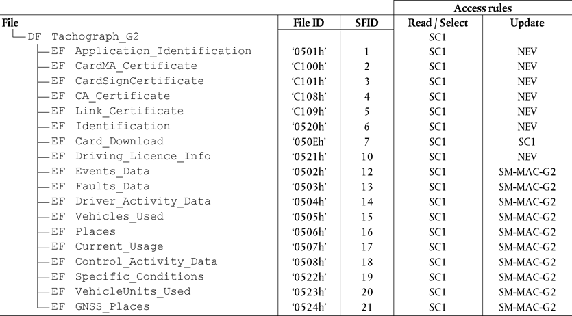
The following abbreviation for the security condition is used in this table:
SC1
ALW OR SM-MAC-G2
TCS_153All EF structures shall be transparent.U.K.
TCS_154The driver card application generation 2 shall have the following data structure:U.K.


TCS_155The following values, used to provide sizes in the table above, are the minimum and maximum record number values the driver card data structure must use for a generation 2 application:U.K.

4.3.Workshop card applicationsU.K.
4.3.1Workshop card application generation 1U.K.
TCS_156After its personalisation, the workshop card application generation 1 shall have the following permanent file structure and file access rules:U.K.

The following abbreviations for the security conditions are used in this table:
SC1
ALW OR SM-MAC-G2
SC2
ALW OR SM-MAC-G1 OR SM-MAC-G2
SC3
SM-MAC-G1 OR SM-MAC-G2
For the READ BINARY command with even INS byte:
(SM-C-MAC-G1 AND SM-R-ENC-MAC-G1) OR
(SM-C-MAC-G2 AND SM-R-ENC-MAC-G2)
For the READ BINARY command with odd INS byte (if supported): NEV]
TCS_157All EF structures shall be transparent.U.K.
TCS_158The workshop card application generation 1 shall have the following data structure:U.K.


TCS_159The following values, used to provide sizes in the table above, are the minimum and maximum record number values the workshop card data structure must use for a generation 1 application:U.K.

4.3.2Workshop card application generation 2U.K.
TCS_160After its personalisation, the workshop card application generation 2 shall have the following permanent file structure and file access rules.U.K.
Note: The short EF identifier SFID is given as decimal number, e.g. the value 30 corresponds to 11110 in binary.U.K.

The following abbreviations for the security conditions are used in this table:
SC1
ALW OR SM-MAC-G2
SC5
For the Read Binary command with even INS byte: SM-C-MAC-G2 AND SM-R-ENC-MAC-G2
For the Read Binary command with odd INS byte (if supported): NEV
TCS_161All EFs structures shall be transparent.U.K.
TCS_162The workshop card application generation 2 shall have the following data structure:U.K.

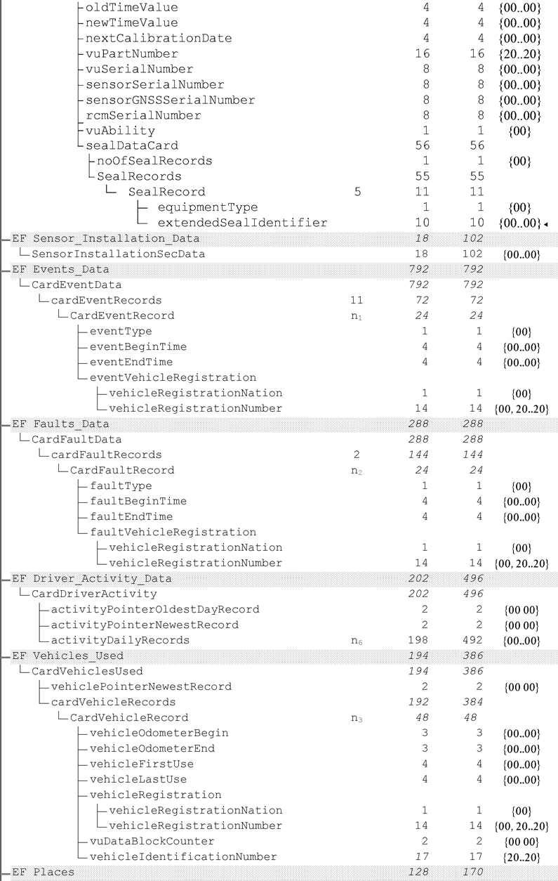

TCS_163The following values, used to provide sizes in the table above, are the minimum and maximum record number values the workshop card data structure must use for a generation 2 application:U.K.

4.4.Control card applicationsU.K.
4.4.1Control Card application generation 1U.K.
TCS_164After its personalisation, the control card application generation 1 shall have the following permanent file structure and file access rules:U.K.

The following abbreviations for the security conditions are used in this table:
SC1
ALW OR SM-MAC-G2
SC2
ALW OR SM-MAC-G1 OR SM-MAC-G2
SC3
SM-MAC-G1 OR SM-MAC-G2
SC6
EXT-AUT-G1 OR SM-MAC-G1 OR SM-MAC-G2
TCS_165All EF structures shall be transparent.U.K.
TCS_166The control card application generation 1 shall have the following data structure:U.K.

TCS_167The following values, used to provide sizes in the table above, are the minimum and maximum record number values the control card data structure must use for a generation 1 application:U.K.

4.4.2Control card application generation 2U.K.
TCS_168After its personalisation, the control card application generation 2 shall have the following permanent file structure and file access rules.U.K.
Note: The short EF identifier SFID is given as decimal number, e.g. the value 30 corresponds to 11110 in binary.U.K.

The following abbreviation for the security condition is used in this table:
SC1
ALW OR SM-MAC-G2
TCS_169All EF structures shall be transparent.U.K.
TCS_170The control card application generation2 shall have the following data structure:U.K.

TCS_171The following values, used to provide sizes in the table above, are the minimum and maximum record number values the control card data structure must use for a generation 2 application:U.K.

4.5.Company card applicationsU.K.
4.5.1Company card application generation 1U.K.
TCS_172After its personalisation, the company card application generation 1 shall have the following permanent file structure and file access rules:U.K.

The following abbreviations for the security conditions are used in this table:
SC1
ALW OR SM-MAC-G2
SC2
ALW OR SM-MAC-G1 OR SM-MAC-G2
SC3
SM-MAC-G1 OR SM-MAC-G2
SC6
EXT-AUT-G1 OR SM-MAC-G1 OR SM-MAC-G2
TCS_173All EF structures shall be transparent.U.K.
TCS_174The company card application generation 1 shall have the following data structure:U.K.

TCS_175The following values, used to provide sizes in the table above, are the minimum and maximum record number values the company card data structure must use for a generation 1 application:U.K.

4.5.2Company card application generation 2U.K.
TCS_176After its personalisation, the company card application generation 2 shall have the following permanent file structure and file access rules.U.K.
Note: The short EF identifier SFID is given as decimal number, e.g. the value 30 corresponds to 11110 in binary.U.K.

The following abbreviation for the security condition is used in this table:
SC1
ALW OR SM-MAC-G2
TCS_177All EF structures shall be transparent.U.K.
TCS_178The company card application generation 2 shall have the following data structure:U.K.

TCS_179The following values, used to provide sizes in the table above, are the minimum and maximum record number values the company card data structure must use for a generation 2 application:U.K.

Appendix 3
PICTOGRAMSU.K.
PIC_001The tachograph may optionally use the following pictograms and pictogram combinations (or pictograms and combination similar enough to be unambiguously identifiable with these):U.K.
1.
BASIC PICTOGRAMS
| People | Actions | Modes of operation | |
|---|---|---|---|
 | Company | Company mode | |
 | Controller | Control | Control mode |
 | Driver | Driving | Operational mode |
 | Workshop/test station | Inspection/calibration | Calibration mode |
 | Manufacturer |
| Activities | Duration | |
|---|---|---|
 | Available | Current availability period |
 | Driving | Continuous driving time |
 | Rest | Current rest period |
 | Other Work | Current work period |
 | Break | Cumulative break time |
 | Unknown |
| Equipment | Functions | |
|---|---|---|
 | Driver slot | |
 | Co-driver slot | |
 | Card | |
 | Clock | |
 | Display | Displaying |
 | External storage | Downloading |
 | Power supply | |
 | Printer/printout | Printing |
 | Sensor | |
 | Tyre size | |
 | Vehicle/vehicle unit | |
 | GNSS facility | |
 | Remote Detection facility | |
 | ITS interface |
| Specific conditions | |
|---|---|
 | Out of scope |
 | Ferry/train crossing |
| Miscellaneous | |||
|---|---|---|---|
 | Events |  | Faults |
 | Start of daily work period |  | End of daily work period |
 | Location | ||
 | Manual entry of driver activities | ||
 | Security | ||
 | Speed | ||
 | Time | ||
 | Total/summary |
| Qualifiers | |
|---|---|
| 24h | Daily |
 | Weekly |
 | Two weeks |
 | From or to |
2.
PICTOGRAM COMBINATIONS
| Miscellaneous | |||
|---|---|---|---|
 | Control place | ||
 | Location start of daily work period |  | Location end of daily work period |
 | [F12Position after 3 hours accumulated driving time ] | ||
 | From time |  | To time |
 | From vehicle | ||
 | Out of scope begin |  | Out of scope end |
| Cards | |
|---|---|
 | Driver card |
 | Company card |
 | Control card |
 | Workshop card |
 | No card |
| Driving | |
|---|---|
 | Crew driving |
 | Driving time for one week |
 | Driving time for two weeks |
| Printouts | |
|---|---|
 | Driver activities from card daily printout |
 | Driver activities from VU daily printout |
 | Events and faults from card printout |
 | Events and faults from VU printout |
 | Technical data printout |
 | Over speeding printout |
| Events | |
|---|---|
 | Insertion of a non valid card |
 | Card conflict |
 | Time overlap |
 | Driving without an appropriate card |
 | Card insertion while driving |
 | Last card session not correctly closed |
 | Over speeding |
 | Power supply interruption |
 | Motion data error |
 | Vehicle motion conflict |
 | Security breach |
 | [F2Time conflict or time adjustment (by workshop)] |
 | Over speeding control |
 | [F12Absence of position information from GNSS receiver or Communication error with the external GNSS facility |
 | Communication error with the remote communication facility] |
| Faults | |
|---|---|
 | Card fault (driver slot) |
 | Card fault (co-driver slot) |
 | Display fault |
 | Downloading fault |
 | Printer fault |
 | Sensor fault |
 | VU internal fault |
 | GNSS fault |
 | Remote Detection fault |
| Manual entries procedure | |
|---|---|
 | Still same daily work period ? |
 | End of previous work period ? |
 | Confirm or enter location of end of work period |
 | Enter start time |
 | Enter location of start of work period. |
Note: Additional pictogram combinations to form printout blocks or record identifiers are defined in Appendix 4.U.K.
Appendix 4
PRINTOUTSU.K.
1.GENERALITIESU.K.
Each printout is built up by chaining various data blocks, possibly identified with a block identifier.
A data block contains one or more records, possibly identified with a record identifier.
PRT_001
When a block identifier immediately precedes a record identifier, the record identifier is not printed.
PRT_002
In the case where a data item is unknown, or must not be printed for data access rights reasons, spaces are printed instead.
PRT_003
If the content of a complete line is unknown, or need not to be printed, then the complete line is omitted.
PRT_004
Numerical data fields are printed right aligned, with a space separator for thousands and millions, and without leading zeros.
PRT_005
String data fields are printed left aligned and filled up with spaces to data item length, or truncated to data item length when needed (names and addresses).
PRT_006
In case of a line-break due to a long text a special character (dot at middle line-height, ‘•’) should be printed as first character in the new line.
2.DATA BLOCKS SPECIFICATIONU.K.
In this chapter the following format notation conventions have been used:
Characters printed in bold denote plain text to be printed (printing remains in normal characters),
Normal characters denote variables (pictograms or data) to be replaced by their values for printing,
Variable names have been padded with underscores to show the data item length available for the variable,
Dates are specified with a ‘dd/mm/yyyy’ (day, month, year) format. A ‘dd.mm.yyyy’ format may also be used,
The term ‘card identification’ denotes the composition of: the type of card through a card pictograms combination, the card issuing Member State code, a forward slash character and the card number with the replacement index and the renewal index separated with a space:
P x x x / x x x x x x x x x x x x x x x x Card Pictogram combination Issuing Member State code First 14 characters of card number
(possibly including a consecutive index)
Replacement index Renewal index

PRT_007Printouts shall use the following data blocks and/or data records, in accordance with the following meanings and formats:U.K.


3.PRINTOUT SPECIFICATIONSU.K.
In this chapter the following notation conventions have been used:
| N | Print block or record number N |
| N | Print block or record number N repeated as many times as necessary |
| X/Y | Print blocks or records X and/or Y as needed, and repeating as many times as necessary. |
3.1.Driver Activities from Card Daily PrintoutU.K.
PRT_008The driver activities from card daily printout shall be in accordance with the following format:U.K.
| 1 | Date and time at which the document is printed |
| 2 | Type of printout |
| 3 | Controller identification (if a control card is inserted in the VU) |
| 3 | Driver identification (from card subject of the printout + GEN) |
| 4 | Vehicle identification (vehicle from which printout is taken) |
| 5 | VU identification (VU from which printout is taken + GEN) |
| 6 | Last calibration of this VU |
| 7 | Last control the inspected driver has been subject to |
| 8 | Driver activities delimiter |
| 8a | Out of scope condition in the beginning of this day |
| 8.1a/8.1b/8.1c/8.2/8.3/8.3a/8.4 | Activities of the driver in order of occurrence |
| 11 | Daily summary delimiter |
| 11.4 | Places entered in chronological order |
| [F211.5 | Positions after 3 hours accumulated driving time in chronological order] |
| 11.6 | Activity totals |
| 12.1 | Events or faults from card delimiter |
| 12.4 | Event/Fault records (Last 5 events or faults stored in the card) |
| 13.1 | Events or faults from VU delimiter |
| 13.4 | Event/Fault records (Last 5 events or faults stored or on-going in the VU) |
| 22.1 | Control place |
| 22.2 | Controller's signature |
| 22.5 | Driver's signature |
3.2.Driver Activities from VU Daily PrintoutU.K.
PRT_009The driver activities from VU daily printout shall be in accordance with the following format:U.K.
| [F21 | Date and time at which the document is printed | ||
| 2 | Type of printout | ||
| 3 | Card holder identification (for all cards inserted in VU + GEN) | ||
| 4 | Vehicle identification (vehicle from which printout is taken) | ||
| 5 | VU identification (VU from which printout is taken + GEN) | ||
| 6 | Last calibration of this VU | ||
| 7 | Last control on this tachograph | ||
| 9 | Driver activities delimiter | ||
| 10 | Driver slot delimiter (slot 1) | ||
| 10a | Out of scope condition in the beginning of this day | ||
| 10.1 / 10.2 / 10.3 / 10.3a / 10.4 | Activities in chronological order (driver slot) | ||
| 10 | Co-driver slot delimiter (slot 2) | ||
| 10a | Out of scope condition in the beginning of this day | ||
| 10.1 / 10.2 / 10.3 / 10.3a / 10.4 | Activities in chronological order (co-driver slot) | ||
| 11 | Daily summary delimiter | ||
| 11.1 | Summary of periods without card in driver slot | ||
| 11.4 | Places entered in chronological order | ||
| 11.5 | Positions after 3 hours accumulated driving time in chronological order | ||
| 11.7 | Activity totals | ||
| 11.2 | Summary of periods without card in co-driver slot | ||
| 11.4 | Places entered in chronological order | ||
| 11.5 | Positions after 3 hours accumulated driving time in chronological order | ||
| 11.8 | Activity totals | ||
| 11.3 | Summary of activities for a driver both slots included | ||
| 11.4 | Places entered by this driver in chronological order | ||
| 11.5 | Positions after 3 hours accumulated driving time in chronological order | ||
| 11.9 | Activity totals for this driver | ||
| 13.1 | Events faults delimiter | ||
| 13.4 | Event/Fault records (Last 5 events or faults stored or on-going in the VU) | ||
| 22.1 | Control place | ||
| 22.2 | Controller’s signature | ||
| 22.3 | From time (space available for a driver without a card to indicate | ||
| 22.4 | To time which periods are relevant to himself) | ||
| 22.5 | Driver's signature] | ||
3.3.Events and Faults from Card PrintoutU.K.
PRT_010The events and faults from card printout shall be in accordance with the following format:U.K.
| 1 | Date and time at which the document is printed |
| 2 | Type of printout |
| 3 | Controller identification (if a control card is inserted in the VU + GEN) |
| 3 | Driver identification (from card subject of the printout) |
| 4 | Vehicle identification (vehicle from which printout is taken) |
| 12.2 | Events delimiter |
| 12.4 | Event records (all events stored on the card) |
| 12.3 | Faults delimiter |
| 12.4 | Fault records (all faults stored on the card) |
| 22.1 | Control place |
| 22.2 | Controller's signature |
| 22.5 | Driver's signature |
3.4.Events and Faults from VU PrintoutU.K.
PRT_011The events and faults from VU printout shall be in accordance with the following format:U.K.
| 1 | Date and time at which the document is printed |
| 2 | Type of printout |
| 3 | Card holder identification (for all cards inserted in VU + GEN) |
| 4 | Vehicle identification (vehicle from which printout is taken) |
| 13.2 | Events delimiter |
| 13.4 | Event records (All Events stored or on-going in the VU) |
| 13.3 | Faults delimiter |
| 13.4 | Fault records (All Faults stored or on-going in the VU) |
| 22.1 | Control place |
| 22.2 | Controller's signature |
| 22.5 | Driver's signature |
3.5.Technical data PrintoutU.K.
PRT_012The technical data printout shall be in accordance with the following format:U.K.
| 1 | Date and time at which the document is printed |
| 2 | Type of printout |
| 3 | Card holder identification (for all cards inserted in VU + GEN) |
| 4 | Vehicle identification (vehicle from which printout is taken) |
| 14 | VU identification |
| 15 | Sensor identification |
| 15.1 | Sensor Pairing data (all data available in chronological order) |
| 16 | GNSS identification |
| 16.1 | External GNSS facility coupling data (all data available in chronological order) |
| 17 | Calibration data delimiter |
| 17.1 | Calibration records (all records available in chronological order) |
| 18 | Time adjustment delimiter |
| 18.1 | Time adjustment records (all records available from time adjustment and from calibration data records) |
| 19 | Most recent event and Fault recorded in the VU |
3.6.Over speeding PrintoutU.K.
PRT_013The over speeding printout shall be in accordance with the following format:U.K.
| 1 | Date and time at which the document is printed |
| 2 | Type of printout |
| 3 | Card holder identification (for all cards inserted in VU + GEN) |
| 4 | Vehicle identification (vehicle from which printout is taken) |
| 20 | Over speeding control information |
| 21.1 | Over speeding data identifier |
| 21.4/21.5 | First over speeding after the last calibration |
| 21.2 | Over speeding data identifier |
| 21.4/21.5 | The 5 most serious over speeding events over the last 365 days |
| 21.3 | Over speeding data identifier |
| 21.4/21.5 | The most serious over speeding for each of the last 10 days of occurrence |
| 22.1 | Control place |
| 22.2 | Controller's signature |
| 22.5 | Driver's signature |
3.7.Historic of inserted cardsU.K.
[F2PRT_014 The historic of inserted cards printout shall be in accordance with the following format: U.K.
| 1 | Date and time at which the document is printed |
| 2 | Type of printout |
| 3 | Card holder identifications (of all cards inserted in the VU) |
| 23 | Most recent card inserted in the VU |
| 23.1 | Inserted cards (up to 88 records) |
| 12.3 | Faults delimiter] |
Appendix 5
DISPLAYU.K.
In this appendix the following format notation conventions have been used:
characters printed in bold denote plain text to be displayed (display remains in normal character),
normal characters denote variables (pictograms or data) to be replaced by their values for displaying:
— dd mm yyyy:
day, month, year,
— hh:
hours,
— mm:
minutes,
— D:
duration pictogram,
— EF:
event or fault pictograms combination,
— O:
mode of operation pictogram.
DIS_001The tachograph shall display data using the following formats:U.K.
| Data | Format |
|---|---|
| Default display | |
| Local time |  |
| Mode of operation |  |
| Information related to the driver |  |
| Information related to the co-driver |  |
| Out of scope condition opened |  |
| Warning display | |
| Exceeding continuous driving time |  |
| Event or fault |  |
| Other displays | |
| UTC date |  |
| time | |
| Driver's continuous driving time and cumulative break time |  |
| Co-driver's continuous driving time and cumulative break time |  |
| Driver's cumulated driving time for the previous and the current week |  |
| Co-driver's cumulated driving time for the previous and the current week |  |
Appendix 6
FRONT CONNECTOR FOR CALIBRATION AND DOWNLOADU.K.
1.HARDWAREU.K.
1.1.ConnectorU.K.
INT_001The downloading/calibration connector shall be a 6 pin connector, accessible on the front panel without the need to disconnect any part of the tachograph, and shall comply with the following drawing (all dimensions in millimetres):U.K.
The following diagram shows a typical 6 pin mating plug:
1.2.Contact allocationU.K.
INT_002Contacts shall be allocated in accordance with the following table:U.K.
| Pin | Description | Remark |
|---|---|---|
| 1 | Battery minus | Connected to the battery minus of the vehicle |
| 2 | Data communication | K-line (ISO 14230-1) |
| 3 | RxD — Downloading | Data input to tachograph |
| 4 | Input/output signal | Calibration |
| 5 | Permanent power output | The voltage range is specified to be that of the vehicle power minus 3V to allow for the voltage drop across the protective circuitry Output 40 mA |
| 6 | TxD — Downloading | Data output from tachograph |
1.3.Block diagramU.K.
INT_003The block diagram shall comply with the following:U.K.
2.DOWNLOADING INTERFACEU.K.
INT_004The downloading interface shall comply to RS232 specifications.U.K.
INT_005The downloading interface shall use one start bit, 8 data bits LSB first, one even parity bit and 1 stop bit.U.K.
Data byte organisationU.K.
Start bit
:
one bit with logic level 0;
Data bits
:
transmitted with LSB first;
Parity bit
:
even parity
Stop bit
:
one bit with logic level 1
When numerical data composed by more than one byte are transmitted, the most significant byte is transmitted first and the least significant byte last.
INT_006Transmission baud rates shall be adjustable from 9 600 bps to 115 200 bps. Transmission shall be achieved at the highest possible transmission speed, the initial baud rate after a start of communication being set at 9 600 bps.U.K.
3.CALIBRATION INTERFACEU.K.
INT_007The data communication shall comply to ISO 14230-1 Road vehicles — Diagnostic systems — Keyword protocol 2000 — Part 1: Physical layer, First edition: 1999.U.K.
INT_008The input/output signal shall comply with the following electrical specification:U.K.
| Parameter | Minimum | Typical | Maximum | Remark |
|---|---|---|---|---|
| U low (in) | 1,0 V | I = 750 μA | ||
| U high (in) | 4 V | I = 200 μA | ||
| Frequency | 4 kHz | |||
| U low (out) | 1,0 V | I = 1 mA | ||
| U high (out) | 4 V | I = 1 mA |
INT_009The input/output signal shall comply with the following timing diagrams:U.K.
Appendix 7
DATA DOWNLOADING PROTOCOLSU.K.
1.INTRODUCTIONU.K.
This appendix specifies the procedures to follow in order to perform the different types of data download to an External Storage Medium, together with the protocols that must be implemented to assure the correct data transfer and the full compatibility of the downloaded data format to allow any controller to inspect these data and be able to control their authenticity and their integrity before analysing them.
[F21.1. Scope U.K.
Data may be downloaded to an ESM:
from a Vehicle Unit by an Intelligent Dedicated Equipment (IDE) connected to the VU,
from a tachograph card by an IDE fitted with a card interface device (IFD),
from a tachograph card via a vehicle unit by an IDE connected to the VU.
To give the possibility to verify the authenticity and integrity of downloaded data stored on an ESM, data is downloaded with a signature appended in accordance with Appendix 11 Common Security Mechanisms. The source equipment (VU or card) identification and its security certificates (Member state and equipment) are also downloaded. The verifier of the data must possess independently a trusted European public key.
Data downloaded from a VU are signed using Appendix 11 Common Security Mechanisms Part B (Second-generation tachograph system), except when drivers' control is performed by a non EU control authority, using a first generation control card, in which case data are signed using Appendix 11 Common Security Mechanisms Part A (First-generation tachograph system), as requested by Appendix 15 Migration, requirement MIG_015.
This Appendix specifies therefore two types of data downloads from the VU:
Generation 2 type of VU data download, providing the generation 2 data structure, signed using Appendix 11 Common Security Mechanisms Part B,
Generation 1 type of VU data download, providing the generation 1 data structure, signed using Appendix 11 Common Security Mechanisms Part A.
Similarly, there are two types of data downloads from second generation driver cards inserted in a VU, as specified in paragraphs 3 and 4 of this Appendix.]
1.2.Acronyms and notationsU.K.
The following acronyms are used in this appendix:
AID
Application Identifier
ATR
Answer To Reset
CS
Checksum byte
DF
Dedicated File
DS_
Diagnostic Session
EF
Elementary File
ESM
External Storage Medium
FID
File Identifier (File ID)
FMT
Format Byte (first byte of message header)
ICC
Integrated Circuit Card
IDE
Intelligent Dedicated Equipment: The equipment used to perform data downloading to the ESM (e.g. Personal Computer)
IFD
Interface Device
KWP
Keyword Protocol 2000
LEN
Length Byte (last byte of message header)
PPS
Protocol Parameter Selection
PSO
Perform Security Operation
SID
Service Identifier
SRC
Source byte
TGT
Target Byte
TLV
Tag Length Value
TREP
Transfer Response Parameter
TRTP
Transfer Request Parameter
VU
Vehicle Unit
2.V.U. DATA DOWNLOADINGU.K.
2.1.Download procedureU.K.
In order to carry on a VU data download, the operator must perform the following operations:
Insert his tachograph card inside a card slot of the VU(21);
Connect the IDE to the VU download connector;
Establish the connection between the IDE and the VU;
Select on the IDE the data to download and send the request to the VU;
Close the download session.
2.2.Data download protocolU.K.
The protocol is structured on a master-slave basis, with the IDE playing the master role and the VU playing the slave role.
The message structure, types and flow are principally based on the Keyword Protocol 2000 (KWP) (ISO 14230-2 Road vehicles — Diagnostic systems — Keyword protocol 2000 — Part2: Data link layer).
The application layer is principally based on the current draft to date of ISO 14229-1 (Road vehicles — Diagnostic systems — Part 1: Diagnostic services, version 6 of 22 February 2001).
2.2.1Message structureU.K.
DDP_002All the messages exchanged between the IDE and the VU are formatted with a structure consisting of three parts:U.K.
Header composed by a Format byte (FMT), a Target byte (TGT), a Source byte (SRC) and possibly a Length byte (LEN),
Data field composed by a Service Identifier byte (SID) and a variable number of data bytes, which can include an optional diagnostic session byte (DS_) or an optional transfer parameter byte (TRTP or TREP).
Checksum composed by a Checksum byte (CS).
| Header | Data field | Checksum | |||||||
|---|---|---|---|---|---|---|---|---|---|
| FMT | TGT | SRC | LEN | SID | DATA | … | … | … | CS |
| 4 bytes | Max 255 bytes | 1 byte | |||||||
The TGT and SRC byte represent the physical address of the recipient and originator of the message. Values are F0 Hex for the IDE and EE Hex for the VU.
The LEN byte is the length of the Data field part.
The Checksum byte is the 8 bit sum series modulo 256 of all the bytes of the message excluding the CS itself.
FMT, SID, DS_, TRTP and TREP bytes are defined later in this document.
DDP_003In the case where the data to be carried by the message is longer than the space available in the data field part, the message is actually sent in several sub messages. Each sub message bears a header, the same SID, TREP and a 2-byte sub message counter indicating the sub message number within the total message. To enable error checking and abort the IDE acknowledges every sub message. The IDE can accept the sub message, ask for it to be re-transmitted, request the VU to start again or abort the transmission.U.K.
DDP_004If the last sub message contains exactly 255 bytes in the data field, a final sub message with an empty (except SID TREP and sub message counter) data field must be appended to show the end of the message.U.K.
Example:
| Header | SID | TREP | Message | CS |
|---|---|---|---|---|
| 4 Bytes | Longer than 255 Bytes | |||
Will be transmitted as:
| Header | SID | TREP | 00 | 01 | Sub message 1 | CS |
|---|---|---|---|---|---|---|
| 4 Bytes | 255 Bytes | |||||
| Header | SID | TREP | 00 | 02 | Sub message 2 | CS |
|---|---|---|---|---|---|---|
| 4 Bytes | 255 Bytes | |||||
…
| Header | SID | TREP | xx | yy | Sub message n | CS |
|---|---|---|---|---|---|---|
| 4 Bytes | Less than 255 Bytes | |||||
or as:
| Header | SID | TREP | 00 | 01 | Sub message 1 | CS |
|---|---|---|---|---|---|---|
| 4 Bytes | 255 Bytes | |||||
| Header | SID | TREP | 00 | 02 | Sub message 2 | CS |
|---|---|---|---|---|---|---|
| 4 Bytes | 255 Bytes | |||||
…
| Header | SID | TREP | xx | yy | Sub message n | CS |
|---|---|---|---|---|---|---|
| 4 Bytes | 255 Bytes | |||||
| Header | SID | TREP | xx | yy + 1 | CS |
|---|---|---|---|---|---|
| 4 Bytes | 4 bytes | ||||
2.2.2Message typesU.K.
The communication protocol for data download between the VU and the IDE requires the exchange of 8 different message types.
The following table summarises these messages.
| [F2Message Structure | Max 4 Bytes Header | Max 255 Bytes Data | 1 Byte CheckSum | ||||||
|---|---|---|---|---|---|---|---|---|---|
| IDE -> | <- VU | FMT | TGT | SRC | LEN | SID | DS_ / TRTP | DATA | CS |
| Start Communication Request | 81 | EE | F0 | 81 | E0 | ||||
| Positive Response Start Communication | 80 | F0 | EE | 03 | C1 | EA, 8F | 9B | ||
| Start Diagnostic Session Request | 80 | EE | F0 | 02 | 10 | 81 | F1 | ||
| Positive Response Start Diagnostic | 80 | F0 | EE | 02 | 50 | 81 | 31 | ||
| Link Control Service | |||||||||
| Verify Baud Rate (stage 1) | |||||||||
| 9 600 Bd | 80 | EE | F0 | 04 | 87 | 01,01,01 | EC | ||
| 19 200 Bd | 80 | EE | F0 | 04 | 87 | 01,01,02 | ED | ||
| 38 400 Bd | 80 | EE | F0 | 04 | 87 | 01,01,03 | EE | ||
| 57 600 Bd | 80 | EE | F0 | 04 | 87 | 01,01,04 | EF | ||
| 115 200 Bd | 80 | EE | F0 | 04 | 87 | 01,01,05 | F0 | ||
| Positive Response Verify Baud Rate | 80 | F0 | EE | 02 | C7 | 01 | 28 | ||
| Transition Baud Rate (stage 2) | 80 | EE | F0 | 03 | 87 | 02,03 | ED | ||
| Request Upload | 80 | EE | F0 | 0A | 35 | 00,00,00,00,00,FF,FF, FF,FF | 99 | ||
| Positive Response Request Upload | 80 | F0 | EE | 03 | 75 | 00,FF | D5 | ||
| Transfer Data Request | |||||||||
| Overview | 80 | EE | F0 | 02 | 36 | 01 or 21 | 97 | ||
| Activities | 80 | EE | F0 | 06 | 36 | 02 or 22 | Date | CS | |
| Events & Faults | 80 | EE | F0 | 02 | 36 | 03 or 23 | Date | 99 | |
| Detailed Speed | 80 | EE | F0 | 02 | 36 | 04 or 24 | Date | 9 A | |
| Technical Data | 80 | EE | F0 | 02 | 36 | 05 or 25 | Date | 9B | |
| Card download | 80 | EE | F0 | 02 | 36 | 06 | Slot | CS | |
| Positive Response Transfer Data | 80 | F0 | EE | Len | 76 | TREP | Data | CS | |
| Request Transfer Exit | 80 | EE | F0 | 01 | 37 | 96 | |||
| Positive Response Request Transfer Exit | 80 | F0 | EE | 01 | 77 | D6 | |||
| Stop Communication Request | 80 | EE | F0 | 01 | 82 | E1 | |||
| Positive Response Stop Communication | 80 | F0 | EE | 01 | C2 | 21 | |||
| Acknowledge sub message | 80 | EE | F0 | Len | 83 | Data | CS | ||
| Negative responses | |||||||||
| General reject | 80 | F0 | EE | 03 | 7F | Sid Req | 10 | CS | |
| Service not supported | 80 | F0 | EE | 03 | 7F | Sid Req | 11 | CS | |
| Sub function not supported | 80 | F0 | EE | 03 | 7F | Sid Req | 12 | CS | |
| Incorrect Message Length | 80 | F0 | EE | 03 | 7F | Sid Req | 13 | CS | |
| Conditions not correct or Request sequence error | 80 | F0 | EE | 03 | 7F | Sid Req | 22 | CS | |
| Request out of range | 80 | F0 | EE | 03 | 7F | Sid Req | 31 | CS | |
| Upload not accepted | 80 | F0 | EE | 03 | 7F | Sid Req | 50 | CS | |
| Response pending | 80 | F0 | EE | 03 | 7F | Sid Req | 78 | CS | |
| Data not available | 80 | F0 | EE | 03 | 7F | Sid Req | FA | CS] | |
Notes:U.K.
[F12TRTP 21 to 25 are used for Generation 2 type of VU data download requests, TRTP 01 to 05 are used for Generation 1 type of VU data download requests, which can only be accepted by the VU in the frame of drivers' control performed by a non EU control authority, using a first generation control card.
TRTP 11 to 19 and 31 to 39 are reserved for manufacturer specific download requests.]
Sid Req = the Sid of the corresponding request.
TREP = the TRTP of the corresponding request.
Dark cells denote that nothing is transmitted.
The term upload (as seen from the IDE) is used for compatibility with ISO 14229. It means the same as download (as seen from the VU).
Potential 2-byte sub message counters are not shown in this table.
Slot is the slot number, either “1” (card on driver slot) or “2” (card on co-driver slot)
In case the slot is not specified, the VU shall select slot 1 if a card is inserted in this slot and it shall select slot 2 only in case it is specifically selected by the user.
2.2.2.1Start Communication Request (SID 81)U.K.
DDP_005This message is issued by the IDE to establish the communication link with the VU. Initial communications are always performed at 9 600 baud (until baud rate is eventually changed using the appropriate Link control services).U.K.
2.2.2.2Positive Response Start Communication (SID C1)U.K.
DDP_006This message is issued by the VU to answer positively to a start communication request. It includes the 2 key bytes ‘EA’‘8F’ indicating that the unit supports protocol with header including target source and length information.U.K.
2.2.2.3Start Diagnostic Session Request (SID 10)U.K.
DDP_007The Start Diagnostic Session request message is issued by the IDE in order to request a new diagnostic session with the VU. The sub function ‘default session’ (81 Hex) indicates a standard diagnostic session is to be opened.U.K.
2.2.2.4Positive Response Start Diagnostic (SID 50)U.K.
DDP_008The Positive Response Start Diagnostic message is sent by the VU to answer positively to Diagnostic Session Request.U.K.
2.2.2.5Link Control Service (SID 87)U.K.
DDP_052The Link Control Service is used by the IDE to initiate a change in baud rate. This takes place in two steps. In step one the IDE proposes the baud rate change, indicating the new rate. On receipt of a positive message from the VU the IDE sends out confirmation of the baud rate change to the VU (step two). The IDE then changes to the new baud rate. After receipt of the confirmation the VU changes to the new baud rateU.K.
2.2.2.6Link Control Positive Response (SID C7)U.K.
DDP_053The Link Control Positive Response is issued by the VU to answer positively to Link Control Service request (step one). Note that no response is given to the confirmation request (step two).U.K.
2.2.2.7Request Upload (SID 35)U.K.
DDP_009The Request Upload message is issued by the IDE to specify to the VU that a download operation is requested. To meet the requirements of ISO14229 data is included covering address, the size and format details for the data requested. As these are not known to the IDE prior to a download, the memory address is set to 0, format is unencrypted and uncompressed and the memory size is set to the maximum.U.K.
2.2.2.8Positive Response Request Upload (SID 75)U.K.
DDP_010The Positive Response Request Upload message is sent by the VU to indicate to the IDE that the VU is ready to download data. To meet the requirements of ISO 14229 data is included in this positive response message, indicating to the IDE that further Positive Response Transfer Data messages will include 00FF hex bytes maximum.U.K.
2.2.2.9Transfer Data Request (SID 36)U.K.
[F2DDP_011 The Transfer Data Request is sent by the IDE to specify to the VU the type of data that are to be downloaded. A one byte Transfer Request Parameter (TRTP) indicates the type of transfer. U.K.
There are six types of data transfer. For VU data download, two different TRTP values can be used for each transfer type:
| Data transfer type | TRTP value for generation 1 type of VU data download | TRTP value for generation 2 type of VU data download |
|---|---|---|
| Overview | 01 | 21 |
| Activities of a specified date | 02 | 22 |
| Events and faults | 03 | 23 |
| Detailed speed | 04 | 24 |
| Technical data | 05 | 25 |
| Data transfer type | TRTP value |
| Card download | 06] |
[F2DDP_054 It is mandatory for the IDE to request the overview data transfer (TRTP 01 or 21) during a download session as this only will ensure that the VU certificates are recorded within the downloaded file (and allow for verification of digital signature). U.K.
In the second case (TRTP 02 or 22) the Transfer Data Request message includes the indication of the calendar day ( 
2.2.2.10Positive Response Transfer Data (SID 76)U.K.
DDP_012The Positive Response Transfer Data is sent by the VU in response to the Transfer Data Request. The message contains the requested data, with a Transfer Response Parameter (TREP) corresponding to the TRTP of the request.U.K.
[F2DDP_055 In the first case (TREP 01 or 21), the VU will send data helping the IDE operator to choose the data he wants to download further. The information contained within this message is: U.K.
Security certificates,
Vehicle identification,
VU current date and time,
Min and Max downloadable date (VU data),
Indication of cards presence in the VU,
Previous download to a company,
Company locks,
Previous controls.]
2.2.2.11Request Transfer Exit (SID 37)U.K.
DDP_013The Request Transfer Exit message is sent by the IDE to inform the VU that the download session is terminated.U.K.
2.2.2.12Positive Response Request Transfer Exit (SID 77)U.K.
DDP_014The Positive Response Request Transfer Exit message is sent by the VU to acknowledge the Request Transfer Exit.U.K.
2.2.2.13Stop Communication Request (SID 82)U.K.
DDP_015The Stop Communication Request message is sent by the IDE to disconnect the communication link with the VU.U.K.
2.2.2.14Positive Response Stop Communication (SID C2)U.K.
DDP_016The Positive Response Stop Communication message is sent by the VU to acknowledge the Stop Communication Request.U.K.
2.2.2.15Acknowledge Sub Message (SID 83)U.K.
DDP_017The Acknowledge Sub Message is sent by the IDE to confirm receipt of each part of a message that is being transmitted as several sub messages. The data field contains the SID received from the VU and a 2-byte code as follows:U.K.
MsgC+1 Acknowledges correct receipt of sub message number MsgC.
Request from the IDE to the VU to send next sub message
MsgC indicates a problem with the receipt of sub message number MsgC.
Request from the IDE to the VU to send the sub message again.
FFFF requests termination of the message.
This can be used by the IDE to end the transmission of the VU message for any reason.
The last sub message of a message (LEN byte < 255) may be acknowledged using any of these codes or not acknowledged.
The VU responses that will consist of several sub messages are:
Positive Response Transfer Data (SID 76)
2.2.2.16Negative Response (SID 7F)U.K.
DDP_018The Negative Response message is sent by the VU in response to the above request messages when the VU cannot satisfy the request. The data fields of the message contains the SID of the response (7F), the SID of the request, and a code specifying the reason of the negative response. The following codes are available:U.K.
10 general reject
The action cannot be performed for a reason not covered below.
11 service not supported
The SID of the request is not understood.
12 sub function not supported
The DS_ or TRTP of the request is not understood, or there are no further sub messages to be transmitted.
13 incorrect message length
The length of the received message is wrong.
22 conditions not correct or request sequence error
The required service is not active or the sequence of request messages is not correct.
31 Request out of range
The request parameter record (data field) is not valid.
50 upload not accepted
The request cannot be performed (VU in a non appropriate mode of operation or internal fault of the VU).
78 response pending
The action requested cannot be completed in time and the VU is not ready to accept another request.
[F2FA data not available
The data object of a data transfer request are not available in the VU (e.g. no card is inserted, generation 1 type of VU data download requested outside the frame of a driver’s control by a non EU control authority…).]
2.2.3Message flowU.K.
A typical message flow during a normal data download procedure is the following:
| IDE | VU | |
|---|---|---|
| Start Communication Request | ⇨ | |
| ⇦ | Positive Response | |
| Start Diagnostic Service Request | ⇨ | |
| ⇦ | Positive Response | |
| Request Upload | ⇨ | |
| ⇦ | Positive Response | |
| Transfer Data Request Overview | ⇨ | |
| ⇦ | Positive Response | |
| Transfer Data Request #2 | ⇨ | |
| ⇦ | Positive Response #1 | |
| Acknowledge Sub Message #1 | ⇨ | |
| ⇦ | Positive Response #2 | |
| Acknowledge Sub Message #2 | ⇨ | |
| ⇦ | Positive Response #m | |
| Acknowledge Sub Message #m | ⇨ | |
| ⇦ | Positive Response (Data Field < 255 Bytes) | |
| Acknowledge Sub Message (optional) | ⇨ | |
| … | ||
| Transfer Data Request #n | ⇨ | |
| ⇦ | Positive Response | |
| Request Transfer Exit | ⇨ | |
| ⇦ | Positive Response | |
| Stop Communication Request | ⇨ | |
| ⇦ | Positive Response | |
2.2.4TimingU.K.
DDP_019During normal operation the timing parameters shown in the following figure are relevant:U.K.

Where:
P1
=
Inter byte time for VU response.
P2
=
Time between end of IDE request and start of VU response, or between end of IDE acknowledge and start of next VU response.
P3
=
Time between end of VU response and start of new IDE request, or between end of VU response and start of IDE acknowledge, or between end of IDE request and start of new IDE request if VU fails to respond.
P4
=
Inter byte time for IDE request.
P5
=
Extended value of P3 for card downloading.
The allowed values for the timing parameters are showed in the following table (KWP extended timing parameters set, used in case of physical addressing for faster communication).
a If the VU responds with a Negative Response containing a code meaning ‘request correctly received, response pending’, this value is extended to the same upper limit value of P3. | ||
| Timing Parameter | Lower limitValue (ms) | Upper limitValue (ms) |
|---|---|---|
| P1 | 0 | 20 |
| P2 | 20 | 1 000a |
| P3 | 10 | 5 000 |
| P4 | 5 | 20 |
| P5 | 10 | 20 minutes |
2.2.5Error handlingU.K.
If an error occurs during the message exchange, the message flow scheme is modified depending on which equipment has detected the error and on the message generating the error.
In figure 2 and figure 3 the error handling procedures for the VU and the IDE are respectively shown.
2.2.5.1Start Communication phaseU.K.
DDP_020If the IDE detects an error during the Start Communication phase, either by timing or by the bit stream, then it will wait for a period P3 min before issuing again the request.U.K.
DDP_021If the VU detects an error in the sequence coming from the IDE, it shall send no response and wait for another Start Communication Request message within a period P3 max.U.K.
2.2.5.2Communication phaseU.K.
Two different error handling areas can be defined:
1.
The VU detects an IDE transmission error.
DDP_022
For every received message the VU shall detect timing errors, byte format errors (e.g. start and stop bit violations) and frame errors (wrong number of bytes received, wrong checksum byte).
DDP_023
If the VU detects one of the above errors, then it sends no response and ignores the message received.
DDP_024
The VU may detect other errors in the format or content of the received message (e.g. message not supported) even if the message satisfies the length and checksum requirements; in such a case, the VU shall respond to the IDE with a Negative Response message specifying the nature of the error.

2.
The IDE detects a VU transmission error.
DDP_025
For every received message the IDE shall detect timing errors, byte format errors (e.g. start and stop bit violations) and frame errors (wrong number of bytes received, wrong checksum byte).
DDP_026
The IDE shall detect sequence errors, e.g. incorrect sub message counter increments in successive received messages.
DDP_027
If the IDE detects an error or there was no response from the VU within a P2 max period, the request message will be sent again for a maximum of three transmissions in total. For the purposes of this error detection a sub message acknowledge will be considered as a request to the VU.
DDP_028
The IDE shall wait at least for a period of P3 min before beginning each transmission; the wait period shall be measured from the last calculated occurrence of a stop bit after the error was detected.

2.2.6Response Message contentU.K.
This paragraph specifies the content of the data fields of the various positive response messages.
Data elements are defined in Appendix 1 data dictionary.
Remark: For generation 2 downloads, each top-level data element is represented by a record array, even if it contains only one record. A record array starts with a header; this header contains the record type, the record size and the number of records. Record arrays are named by ‘…RecordArray’ (with header) in the following tables.U.K.
2.2.6.1Positive Response Transfer Data OverviewU.K.
DDP_029 [F2The data field of the ‘Positive Response Transfer Data Overview’ message shall provide the following data in the following order under the SID 76 Hex, the TREP 01 or 21 Hex and appropriate sub message splitting and counting:] U.K.
| [F2Data structure generation 1 (TREP 01 Hex)] | ||
| Data element | Comment | |
|---|---|---|
  | VU Security certificates | |
  | Vehicle identification | |
 | VU current date and time | |
 | Downloadable period | |
 | Type of cards inserted in the VU | |
 | Previous VU download | |
 | All company locks stored. If the section is empty, only noOfLocks = 0 is sent. | |
 | All control records stored in the VU. If the section is empty, only noOfControls = 0 is sent | |
 | RSA signature of all data (except certificates) starting from VehicleIdentificationNumber down to last byte of last VuControlActivityData. | |
| [F2Data structure generation 2 (TREP 21 Hex)] | ||
| Data element | Comment | |
|---|---|---|
 | Member state certificate | |
 | VU certificate | |
 | Vehicle identification | |
 | Vehicle registration number | |
 | VU current date and time | |
 | Downloadable period | |
 | Type of cards inserted in the VU | |
 | Previous VU download | |
 | All company locks stored. If the section is empty, an array header with noOfRecords = 0 is sent | |
 | All control records stored in the VU. If the section is empty, an array header with noOfRecords = 0 is sent | |
 | ECC signature of all preceding data except the certificates. | |
2.2.6.2Positive Response Transfer Data ActivitiesU.K.
DDP_030 [F2The data field of the ‘Positive Response Transfer Data Activities’ message shall provide the following data in the following order under the SID 76 Hex, the TREP 02 or 22 Hex and appropriate sub message splitting and counting:] U.K.
| [F2Data structure generation 1 (TREP 02 Hex)] | ||
| Data element | Comment | |
|---|---|---|
 | Date of day downloaded | |
 | Odometer at end of downloaded day | |
 | Cards insertion withdrawal cycles data.
| |
 | Slots status at 00:00 and activity changes recorded for the day downloaded. | |
 | Places related data recorded for the day downloaded. If the section is empty, only noOfPlaceRecords = 0 is sent. | |
 | Specific conditions data recorded for the day downloaded. If the section is empty, only noOfSpecificConditionRecords=0 is sent | |
 | RSA signature of all data starting from TimeReal down to last byte of last specific condition record. | |
| [F2Data structure generation 2 (TREP 22 Hex)] | ||
| Data element | Comment | |
|---|---|---|
 | Date of day downloaded | |
 | Odometer at end of downloaded day | |
 | Cards insertion withdrawal cycles data.
| |
 | Slots status at 00:00 and activity changes recorded for the day downloaded. | |
 | Places related data recorded for the day downloaded. If the section is empty, an array header with noOfRecords = 0 is sent. | |
 | [F2 GNSS positions of the vehicle when the accumulated driving time of the vehicle reaches a multiple of three hours. If the section is empty, an array header with noOfRecords = 0 is sent.] | |
 | Specific conditions data recorded for the day downloaded. If the section is empty, an array header with noOfRecords =0 is sent | |
 | ECC signature of all preceding data. | |
2.2.6.3Positive Response Transfer Data Events and FaultsU.K.
DDP_031 [F2The data field of the ‘Positive Response Transfer Data Events and Faults’ message shall provide the following data in the following order under the SID 76 Hex, the TREP 03 or 23 Hex and appropriate sub message splitting and counting:] U.K.
| [F2Data structure generation 1 (TREP 03 Hex)] | ||
| Data element | Comment | |
|---|---|---|
 | All faults stored or on-going in the VU. If the section is empty, only noOfVuFaults = 0 is sent. | |
 | All events (except over speeding) stored or on-going in the VU. If the section is empty, only noOfVuEvents = 0 is sent. | |
 | Data related to last over speeding control (default value if no data). | |
 | All over speeding events stored in the VU. If the section is empty, only noOfVuOverSpeedingEvents = 0 is sent. | |
 | All time adjustment events stored in the VU (outside the frame of a full calibration). If the section is empty, only noOfVuTimeAdjRecords = 0 is sent. | |
 | RSA signature of all data starting from noOfVuFaults down to last byte of last time adjustment record | |
| [F2Data structure generation 2 (TREP 23 Hex)] | ||
| Data element | Comment | |
|---|---|---|
 | All faults stored or on-going in the VU. If the section is empty, an array header with noOfRecords = 0 is sent. | |
 | All events (except over speeding) stored or on-going in the VU. If the section is empty, an array header with noOfRecords = 0 is sent. | |
 | Data related to last over speeding control (default value if no data). | |
 | All over speeding events stored in the VU. If the section is empty, an array header with noOfRecords = 0 is sent. | |
 | All time adjustment events stored in the VU (outside the frame of a full calibration). If the section is empty, an array header with noOfRecords = 0 is sent. | |
| F25 | ||
 | ECC signature of all preceding data. | |
Textual Amendments
2.2.6.4Positive Response Transfer Data Detailed SpeedU.K.
DDP_032 [F2The data field of the ‘Positive Response Transfer Data Detailed Speed’ message shall provide the following data in the following order under the SID 76 Hex, the TREP 04 or 24 Hex and appropriate sub message splitting and counting:] U.K.
| [F2Data structure generation 1 (TREP 04)] | ||
| Data element | Comment | |
|---|---|---|
 | All detailed speed stored in the VU (one speed block per minute during which the vehicle has been moving) 60 speed values per minute (one per second). | |
 | RSA signature of all data starting from noOfSpeedBlocks down to last byte of last speed block. | |
| [F2Data structure generation 2 (TREP 24)] | ||
| Data element | Comment | |
|---|---|---|
 | All detailed speed stored in the VU (one speed block per minute during which the vehicle has been moving) 60 speed values per minute (one per second). | |
 | ECC signature of all preceding data. | |
2.2.6.5Positive Response Transfer Data Technical DataU.K.
DDP_033 [F2The data field of the ‘Positive Response Transfer Data Technical Data’ message shall provide the following data in the following order under the SID 76 Hex, the TREP 05 or 25 Hex and appropriate sub message splitting and counting:] U.K.
| [F2Data structure generation 1 (TREP 05)] | ||
| Data element | Comment | |
|---|---|---|
 | ||
 | ||
 | All calibration records stored in the VU. | |
 | RSA signature of all data starting from vuManufacturerName down to last byte of last VuCalibrationRecord. | |
| [F2Data structure generation 2 (TREP 25)] | ||
| Data element | Comment | |
|---|---|---|
 | ||
 | All MS pairings stored in the VU | |
 | All external GNSS facility couplings stored in the VU | |
 | All calibration records stored in the VU. | |
 | All card insertion data stored in the VU. | |
 | ||
 | ||
 | ECC signature of all preceding data. | |
2.3.ESM File storageU.K.
DDP_034When a download session has included a VU data transfer, the IDE shall store within one single physical file all data received from the VU during the download session within Positive Response Transfer Data messages. Data stored excludes message headers, sub-message counters, empty sub-messages and checksums but include the SID and TREP (of the first sub-message only if several sub-messages).U.K.
3.TACHOGRAPH CARDS DOWNLOADING PROTOCOLU.K.
3.1.ScopeU.K.
This paragraph describes the direct card data downloading of a tachograph card to an IDE. The IDE is not part of the secure environment; therefore no authentication between the card and the IDE is performed.
3.2.DefinitionsU.K.
Download session
:
Each time a download of the ICC data is performed. The session covers the complete procedure from the reset of the ICC by an IFD until the deactivation of the ICC (withdraw of the card or next reset).
Signed Data File
:
A file from the ICC. The file is transferred to the IFD in plain text. On the ICC the file is hashed and signed and the signature is transferred to the IFD.
3.3.Card DownloadingU.K.
[F2DDP_035 The download of a tachograph card includes the following steps: U.K.
Download the common information of the card in the EFs
and
This information is optional and is not secured with a digital signature.
(for first and second generation tachograph cards) Download EFs within
:
Download the EFs
and
This information is not secured with a digital signature.
It is mandatory to download these files for each download session.
Download the other application data EFs (within
) except EF
. This information is secured with a digital signature, using Appendix 11 Common Security Mechanisms Part A.
It is mandatory to download at least the EFs
and
for each download session.
When downloading a driver card it is also mandatory to download the following EFs:
(for second generation tacograph cards only) Except when a download of a driver card inserted in a VU is performed during drivers' control by a non EU control authority, using a first generation control card, download EFs within
:
Download the EFs CardSignCertificate, CA_Certificate and Link_Certificate (if present). This information is not secured with a digital signature.
It is mandatory to download these files for each download session.
Download the other application data EFs (within
) except EF
. This information is secured with a digital signature, using Appendix 11 Common Security Mechanisms Part B.
It is mandatory to download at least the EFs
and
for each download session.
When downloading a driver card it is also mandatory to download the following EFs:
When downloading a driver card, update the
date in EF
, in the
and, if applicable,
DFs.
When downloading a workshop card, reset the calibration counter in EF
in the
and, if applicable,
DFs.
When downloading a workshop card the EF
in the
and, if applicable,
DFs shall not be downloaded.]


3.3.1Initialisation sequenceU.K.
DDP_036The IDE shall initiate the sequence as follows:U.K.
| Card | Direction | IDE/IFD | Meaning/Remarks |
|---|---|---|---|
| ⇦ | Hardware reset | ||
| ATR | ⇨ |
It is optional to use PPS to switch to a higher baud rate as long as the ICC supports it.
3.3.2Sequence for un-signed data filesU.K.
DDP_037 [F2The sequence to download EFs ICC, IC, Card_Certificate (or CardSignCertificate for DF Tachograph_G2), CA_Certificate and Link_Certificate (for DF Tachograph_G2 only) is as follows:] U.K.
| Card | Direction | IDE/IFD | Meaning/Remarks |
|---|---|---|---|
| ⇦ | Select File | Select by File identifiers | |
| OK | ⇨ | ||
| ⇦ | Read Binary | If the file contains more data than the buffer size of the reader or the card the command has to be repeated until the complete file is read. | |
File Data OK | ⇨ | Store data to ESM | according to 3.4 Data storage format |
Note 1: Before selecting the Card_Certificate (or CardSignCertificate) EF, the Tachograph Application must be selected (selection by AID).U.K.
Note 2: Selecting and reading a file may also be performed in one step using a Read Binary command with a short EF identifier.U.K.
3.3.3Sequence for Signed data filesU.K.
DDP_038The following sequence shall be used for each of the following files that has to be downloaded with their signature:U.K.
| [F2Card | Dir | IDE / IFD | Meaning / Remarks |
|---|---|---|---|
 | Select File | ||
| OK |  | ||
 | Perform Hash of File | — Calculates the hash value over the data content of the selected file using the prescribed hash algorithm in accordance with Appendix 11, part A or B. This command is not an ISO-Command. | |
| Calculate Hash of File and store Hash value temporarily | |||
| OK |  | ||
 | Read Binary | If the file contains more data than the buffer of the reader or the card can hold, the command has to be repeated until the complete file is read. | |
File Data OK |  | Store received data to ESM | according to 3.4 Data storage format |
 | PSO: Compute Digital Signature | ||
| Perform Security Operation ‘ Compute Digital Signature ’ using the temporarily stored Hash value | |||
Signature OK |  | Append data to the previous stored data on the ESM | according to 3.4 Data storage format] |
Note: Selecting and reading a file may also be performed in one step using a Read Binary command with a short EF identifier. In this case the EF may be selected and read before the command Perform Hash of File is applied.U.K.
3.3.4Sequence for resetting the calibration counter.U.K.
DDP_039The sequence to reset the  counter in the EF
  in a workshop card is the following:U.K.
| Card | Dir | IDE/IFD | Meaning/Remarks |
|---|---|---|---|
| ⇦ | Select File EF Card_Download | Select by File identifiers | |
| OK | ⇨ | ||
| ⇦ | Update Binary NoOfCalibrationsSinceDownload = ‘00 00’ | ||
| resets card download number | |||
| OK | ⇨ |
Note: Selecting and updating a file may also be performed in one step using an Update Binary command with a short EF identifier.U.K.
3.4.Data storage formatU.K.
3.4.1IntroductionU.K.
DDP_040The downloaded data has to be stored according to the following conditions:U.K.
The data shall be stored transparent. This means that the order of the bytes as well as the order of the bits inside the byte that are transferred from the card has to be preserved during storage.
All files of the card downloaded within a download session are stored in one file on the ESM.
3.4.2File formatU.K.
DDP_041The file format is a concatenation of several TLV objects.U.K.
DDP_042The tag for an EF shall be the FID plus the appendix „00“.U.K.
DDP_043The tag of an EF's signature shall be the FID of the file plus the appendix „01“.U.K.
DDP_044The length is a two byte value. The value defines the number of bytes in the value field. The value „FF FF“ in the length field is reserved for future use.U.K.
DDP_045When a file is not downloaded nothing related to the file shall be stored (no tag and no zero length).U.K.
[F2DDP_046 A signature shall be stored as the next TLV object directly after the TLV object that contains the data of the file. U.K.
| Definition | Meaning | Length |
|---|---|---|
| FID (2 Bytes) || ‘ 00 ’ | Tag for EF (FID) in the  or for common information of the card or for common information of the card | 3 Bytes |
| FID (2 Bytes) || ‘ 01 ’ | Tag for Signature of EF (FID) in the  DF DF | 3 Bytes |
| FID (2 Bytes) || ‘ 02 ’ | Tag for EF (FID) in the  DF DF | 3 Bytes |
| FID (2 Bytes) || ‘ 03 ’ | Tag for Signature of EF (FID) in the  DF DF | 3 Bytes |
| xx xx | Length of Value field | 2 Bytes |
Example of data in a download file on an ESM:


4.DOWNLOADING A TACHOGRAPH CARD VIA A VEHICLE UNIT.U.K.
DDP_047The VU must allow for downloading the content of a driver card inserted to a connected IDE.U.K.
DDP_048The IDE shall send a ‘Transfer Data Request Card Download’ message to the VU to initiate this mode (see 2.2.2.9).U.K.
[F2DDP_049 First generation driver cards: Data shall be downloaded using the first generation data download protocol, and downloaded data shall have the same format as data downloaded from a first generation vehicle unit. U.K.
Second generation driver cards: the VU shall then download the whole card, file by file, in accordance with the card downloading protocol defined in paragraph 3, and forward all data received from the card to the IDE within the appropriate TLV file format (see 3.4.2) and encapsulated within a ‘Positive Response Transfer Data’ message.]
DDP_050The IDE shall retrieve card data from the ‘Positive Response Transfer Data’ message (stripping all headers, SIDs, TREPs, sub message counters, and checksums) and store them within one single physical file as described in paragraph 2.3.U.K.
DDP_051The VU shall then, as applicable, update the  or the
  file of the driver card.U.K.
Appendix 8
CALIBRATION PROTOCOLU.K.
1.INTRODUCTIONU.K.
This appendix describes how data is exchanged between a vehicle unit and a tester via the K-line which forms part of the calibration interface described in Appendix 6. It also describes control of the input/output signal line on the calibration connector.
Establishing K-line communications is described in Section 4 ‘Communication Services’.
This appendix uses the idea of diagnostic ‘sessions’ to determine the scope of K-line control under different conditions. The default session is the ‘StandardDiagnosticSession’ where all data can be read from a vehicle unit but no data can be written to a vehicle unit.
Selection of the diagnostic session is described in Section 5 ‘Management Services’.
This appendix has to be considered as relevant for both generations of VUs and of workshop cards, in compliance with the interoperability requirements laid down in this Regulation.
CPR_001The ‘ECUProgrammingSession’ allows data entry into the vehicle unit. In the case of entry of calibration data, the vehicle unit must, in addition be in the CALIBRATION mode of operation.U.K.
Data transfer via K-line is described in Section 6 ‘Data Transmission Services’. Formats of data transferred are detailed in Section 8 ‘dataRecords formats’.
CPR_002The ‘ECUAdjustmentSession’ allows the selection of the I/O mode of the calibration I/O signal line via the K-line interface. Control of the calibration I/O signal line is described in section 7 ‘Control of Test Pulses — Input/Output Control functional unit’.U.K.
CPR_003Throughout this document the address of the tester is referred to as ‘tt’. Although there may be preferred addresses for testers, the VU shall respond correctly to any tester address. The physical address of the VU is 0xEE.U.K.
2.TERMS, DEFINITIONS AND REFERENCESU.K.
The protocols, messages and error codes are principally based on a draft of ISO 14229-1 (Road vehicles — Diagnostic systems — Part 1: Diagnostic services, version 6 of 22 February 2001).
Byte encoding and hexadecimal values are used for the service identifiers, the service requests and responses, and the standard parameters.
The term ‘tester’ refers to the equipment used to enter programming/calibration data into the VU.
The terms ‘client’ and ‘server’ refer to the tester and the VU respectively.
The term ECU means ‘Electronic Control Unit’ and refers to the VU.
References:U.K.
[F2ISO 14230-2: Road Vehicles -Diagnostic Systems — Keyword Protocol 2000- Part 2: Data Link Layer.
First edition: 1999.]
3.OVERVIEW OF SERVICESU.K.
3.1.Services availableU.K.
The following table provides an overview of the services that will be available in the tachograph and are defined in this document.
CPR_004The table indicates the services that are available in an enabled diagnostic session.U.K.
The 1st column lists the services that are available.
The 2nd column includes the section number in this appendix where of service is further defined.
The 3rd column assigns the service identifier values for request messages.
The 4th column specifies the services of the ‘StandardDiagnosticSession’ (SD) which must be implemented in each VU.
The 5th column specifies the services of the ‘ECUAdjustmentSession’ (ECUAS) which must be implemented to allow control of the I/O signal line in the front panel calibration connector of the VU.
The 6th column specifies the services of the ‘ECUProgrammingSession’ (ECUPS) which must be implemented to allow for programming of parameters in the VU.
Table 1
Service Identifier value summary table
■ This symbol indicates that the service is mandatory in this diagnostic session. No symbol indicates that this service is not allowed in this diagnostic session. | |||||
| Diagnostic Sessions | |||||
|---|---|---|---|---|---|
| Diagnostic Service Name | Section No. | SId Req.Value | SD | ECUAS | ECUPS |
| StartCommunication | 4.1 | 81 | ■ | ■ | ■ |
| StopCommunication | 4.2 | 82 | ■ | ||
| TesterPresent | 4.3 | 3E | ■ | ■ | ■ |
| StartDiagnosticSession | 5.1 | 10 | ■ | ■ | ■ |
| SecurityAccess | 5.2 | 27 | ■ | ■ | ■ |
| ReadDataByIdentifier | 6.1 | 22 | ■ | ■ | ■ |
| WriteDataByIdentifier | 6.2 | 2E | ■ | ||
| InputOutputControlByIdentifier | 7.1 | 2F | ■ | ||
3.2.Response codesU.K.
Response codes are defined for each service.
4.COMMUNICATION SERVICESU.K.
Some services are necessary to establish and maintain communication. They do not appear on the application layer. The services available are detailed in the following table:
Table 2
Communication Services
| Service name | Description |
|---|---|
| StartCommunication | The client requests to start a communication session with a server(s). |
| StopCommunication | The client requests to stop the current communication session. |
| TesterPresent | The client indicates to the server that it is still present. |
CPR_005The StartCommunication Service is used for starting a communication. In order to perform any service, communication must be initialised and the communication parameters need to be appropriate for the desired mode.U.K.
4.1.StartCommunication ServiceU.K.
CPR_006Upon receiving a StartCommunication indication primitive, the VU shall check if the requested communication link can be initialised under the present conditions. Valid conditions for the initialisation of a communication link are described in document ISO 14230-2.U.K.
CPR_007Then the VU shall perform all actions necessary to initialise the communication link and send a StartCommunication response primitive with the Positive Response parameters selected.U.K.
CPR_008If a VU that is already initialised (and has entered any diagnostic session) receives a new StartCommunication Request (e.g. due to error recovery in the tester) the request shall be accepted and the VU shall be reinitialised.U.K.
CPR_009If the communication link cannot be initialised for any reason, the VU shall continue operating as it was immediately prior to the attempt to initialise the communication link..U.K.
CPR_010The StartCommunication Request message must be physically addressed.U.K.
CPR_011Initialising the VU for services is performed through a ‘fast initialisation’ method,U.K.
There is a bus-idle time prior to any activity.
The tester then sends an initialisation pattern.
All information which is necessary to establish communication is contained in the response of the VU.
CPR_012After completion of the initialisation,U.K.
All communication parameters are set to values defined in Table 4 according to the key bytes.
The VU is waiting for the first request of the tester.
The VU is in the default diagnostic mode, i.e. StandardDiagnosticSession.
The calibration I/O signal line is in the default state, i.e. disabled state.
CPR_014The data rate on the K-line shall be 10 400 Baud.U.K.
CPR_016The fast initialisation is started by the tester transmitting a Wake up pattern (Wup) on the K-line. The pattern begins after the idle time on K-line with a low time of Tinil. The tester transmits the first bit of the StartCommunication Service after a time of Twup following the first falling edge.U.K.
CPR_017The timing values for the fast initialisation and communications in general are detailed in the tables below. There are different possibilities for the idle time:U.K.
First transmission after power on, Tidle = 300 ms.
After completion of a StopCommunication Service, Tidle = P3 min.
After stopping communication by time-out P3 max, Tidle = 0.
| Table 3 | |||
| Timing values for fast initialisation | |||
| Parameter | min value | max value | |
|---|---|---|---|
| Tinil | 25 ± 1 ms | 24 ms | 26 ms |
| Twup | 50 ± 1 ms | 49 ms | 51 ms |
| Table 4 | |||
| Communication timing values | |||
| Timing Parameter | Parameter Description | lower limit values [ms] | upper limit values [ms] |
|---|---|---|---|
| min. | max. | ||
| P1 | Inter byte time for VU response | 0 | 20 |
| P2 | Time between tester request and VU response or two VU responses | 25 | 250 |
| P3 | Time between end of VU responses and start of new tester request | 55 | 5 000 |
| P4 | Inter byte time for tester request | 5 | 20 |
CPR_018The message format for fast initialisation is detailed in the following tables. (NOTE: Hex means hexadecimal)U.K.
| Table 5 | |||
| StartCommunication Request Message | |||
| Byte # | Parameter Name | Hex Value | Mnemonic |
|---|---|---|---|
| #1 | Format byte — physical addressing | 81 | FMT |
| #2 | Target address byte | EE | TGT |
| #3 | Source address byte | tt | SRC |
| #4 | StartCommunication Request Service Id | 81 | SCR |
| #5 | Checksum | 00-FF | CS |
| Table 6 | |||
| StartCommunication Positive Response Message | |||
| Byte # | Parameter Name | Hex Value | Mnemonic |
|---|---|---|---|
| #1 | Format byte — physical addressing | 80 | FMT |
| #2 | Target address byte | tt | TGT |
| #3 | Source address byte | EE | SRC |
| #4 | Additional length byte | 03 | LEN |
| #5 | StartCommunication Positive Response Service Id | C1 | SCRPR |
| #6 | Key byte 1 | EA | KB1 |
| #7 | Key byte 2 | 8F | KB2 |
| #8 | Checksum | 00-FF | CS |
CPR_019There is no negative response to the StartCommunication Request message, if there is no positive response message to be transmitted then the VU is not initialised, nothing is transmitted and it remains in its normal operation.U.K.
4.2.StopCommunication ServiceU.K.
4.2.1Message descriptionU.K.
The purpose of this communication layer service is to terminate a communication session.
CPR_020Upon receiving a StopCommunication indication primitive, the VU shall check if the current conditions allow to terminate this communication. In this case the VU shall perform all actions necessary to terminate this communication.U.K.
CPR_021If it is possible to terminate the communication, the VU shall issue a StopCommunication response primitive with the Positive Response parameters selected, before the communication is terminated.U.K.
CPR_022If the communication cannot be terminated by any reason, the VU shall issue a StopCommunication response primitive with the Negative Response parameter selected.U.K.
CPR_023If time-out of P3 max is detected by the VU, the communication shall be terminated without any response primitive being issued.U.K.
4.2.2Message formatU.K.
CPR_024The message formats for the StopCommunication primitives are detailed in the following tables.U.K.
| Table 7 | |||
| StopCommunication Request Message | |||
| Byte # | Parameter Name | Hex Value | Mnemonic |
|---|---|---|---|
| #1 | Format byte — physical addressing | 80 | FMT |
| #2 | Target address byte | EE | TGT |
| #3 | Source address byte | tt | SRC |
| #4 | Additional length byte | 01 | LEN |
| #5 | StopCommunication Request Service Id | 82 | SPR |
| #6 | Checksum | 00-FF | CS |
| Table 8 | |||
| StopCommunication Positive Response Message | |||
| Byte # | Parameter Name | Hex Value | Mnemonic |
|---|---|---|---|
| #1 | Format byte — physical addressing | 80 | FMT |
| #2 | Target address byte | tt | TGT |
| #3 | Source address byte | EE | SRC |
| #4 | Additional length byte | 01 | LEN |
| #5 | StopCommunication Positive Response Service Id | C2 | SPRPR |
| #6 | Checksum | 00-FF | CS |
| Table 9 | |||
| StopCommunication Negative Response Message | |||
| Byte # | Parameter Name | Hex Value | Mnemonic |
|---|---|---|---|
| #1 | Format byte — physical addressing | 80 | FMT |
| #2 | Target address byte | tt | TGT |
| #3 | Source address byte | EE | SRC |
| #4 | Additional length byte | 03 | LEN |
| #5 | negative Response Service Id | 7F | NR |
| #6 | StopCommunication Request Service Identification | 82 | SPR |
| #7 | responseCode = generalReject | 10 | RC_GR |
| #8 | Checksum | 00-FF | CS |
4.2.3Parameter DefinitionU.K.
This service does not require any parameter definition.
4.3.TesterPresent ServiceU.K.
4.3.1Message descriptionU.K.
The TesterPresent service is used by the tester to indicate to the server that it is still present, in order to prevent the server from automatically returning to normal operation and possibly stopping the communication. This service, sent periodically, keeps the diagnostic session/communication active by resetting the P3 timer each time a request for this service is received.
4.3.2Message formatU.K.
CPR_079The message formats for the TesterPresent primitives are detailed in the following tables.U.K.
| Table 10 | ||||
| TesterPresent Request Message | ||||
| Byte # | Parameter Name | Hex Value | Mnemonic | |
|---|---|---|---|---|
| #1 | Format byte — physical addressing | 80 | FMT | |
| #2 | Target address byte | EE | TGT | |
| #3 | Source address byte | tt | SRC | |
| #4 | Additional length byte | 02 | LEN | |
| #5 | TesterPresent Request Service Id | 3E | TP | |
| #6 | Sub Function = responseRequired = | [ yes | 01 | RESPREQ_Y |
| no ] | 02 | RESPREQ_NO | ||
| #7 | Checksum | 00-FF | CS | |
CPR_080If the responseRequired parameter is set to ‘yes’, then the server shall respond with the following positive response message. If set to ‘no’, then no response is sent by the server.U.K.
| Table 11 | |||
| TesterPresent Positive Response Message | |||
| Byte # | Parameter Name | Hex Value | Mnemonic |
|---|---|---|---|
| #1 | Format byte — physical addressing | 80 | FMT |
| #2 | Target address byte | tt | TGT |
| #3 | Source address byte | EE | SRC |
| #4 | Additional length byte | 01 | LEN |
| #5 | TesterPresent Positive Response Service Id | 7E | TPPR |
| #6 | Checksum | 00-FF | CS |
CPR_081The service shall support the following negative responses codes:U.K.
| Table 12 | ||||
| TesterPresent Negative Response Message | ||||
| Byte # | Parameter Name | Hex Value | Mnemonic | |
|---|---|---|---|---|
| #1 | Format byte — physical addressing | 80 | FMT | |
| #2 | Target address byte | tt | TGT | |
| #3 | Source address byte | EE | SRC | |
| #4 | Additional length byte | 03 | LEN | |
| #5 | negative Response Service Id | 7F | NR | |
| #6 | TesterPresent Request Service Identification | 3E | TP | |
| #7 | responseCode = | [SubFunctionNotSupported-InvalidFormat | 12 | RC_SFNS_IF |
| incorrectMessageLength] | 13 | RC_IML | ||
| #8 | Checksum | 00-FF | CS | |
5.MANAGEMENT SERVICESU.K.
The services available are detailed in the following table:
Table 13
Management Services
| Service name | Description |
|---|---|
| StartDiagnosticSession | The client requests to start a diagnostic session with a VU. |
| SecurityAccess | The client requests access to functions restricted to authorised users. |
5.1.StartDiagnosticSession serviceU.K.
5.1.1Message descriptionU.K.
CPR_025The service StartDiagnosticSession is used to enable different diagnostic sessions in the server. A diagnostic session enables a specific set of services according to Table 17. A session can enable vehicle manufacturer specific services which are not part of this document. Implementation rules shall conform to the following requirements:U.K.
There shall be always exactly one diagnostic session active in the VU,
The VU shall always start the StandardDiagnosticSession when powered up. If no other diagnostic session is started, then the StandardDiagnosticSession shall be running as long as the VU is powered,
If a diagnostic session which is already running has been requested by the tester, then the VU shall send a positive response message,
Whenever the tester requests a new diagnostic session, the VU shall first send a StartDiagnosticSession positive response message before the new session becomes active in the VU. If the VU is not able to start the requested new diagnostic session, then it shall respond with a StartDiagnosticSession negative response message, and the current session shall continue.
CPR_026A diagnostic session shall only be started if communication has been established between the client and the VU.U.K.
CPR_027The timing parameters defined in Table 4 shall be active after a successful StartDiagnosticSession with the diagnosticSession parameter set to ‘StandardDiagnosticSession’ in the request message if another diagnostic session was previously active.U.K.
5.1.2Message formatU.K.
CPR_028The message formats for the StartDiagnosticSession primitives are detailed in the following tables.U.K.
| Table 14 | |||
| StartDiagnosticSession Request Message | |||
| Byte # | Parameter Name | Hex Value | Mnemonic |
|---|---|---|---|
| #1 | Format byte — physical addressing | 80 | FMT |
| #2 | Target address byte | EE | TGT |
| #3 | Source address byte | tt | SRC |
| #4 | Additional length byte | 02 | LEN |
| #5 | StartDiagnosticSession Request Service Id | 10 | STDS |
| #6 | diagnosticSession = [one value from Table 17] | xx | DS_… |
| #7 | Checksum | 00-FF | CS |
| Table 15 | |||
| StartDiagnosticSession Positive Response Message | |||
| Byte # | Parameter Name | Hex Value | Mnemonic |
|---|---|---|---|
| #1 | Format byte — physical addressing | 80 | FMT |
| #2 | Target address byte | tt | TGT |
| #3 | Source address byte | EE | SRC |
| #4 | Additional length byte | 02 | LEN |
| #5 | StartDiagnosticSession Positive Response Service Id | 50 | STDSPR |
| #6 | diagnosticSession = [same value as in byte #6 Table 14] | xx | DS_… |
| #7 | Checksum | 00-FF | CS |
| Table 16 | ||||
| StartDiagnosticSession Negative Response Message | ||||
a – the value inserted in byte #6 of the request message is not supported, i.e. not in Table 17, | ||||
b – the length of the message is wrong, | ||||
c – the criteria for the request StartDiagnosticSession are not met. | ||||
| Byte # | Parameter Name | Hex Value | Mnemonic | |
|---|---|---|---|---|
| #1 | Format byte — physical addressing | 80 | FMT | |
| #2 | Target address byte | tt | TGT | |
| #3 | Source address byte | EE | SRC | |
| #4 | Additional length byte | 03 | LEN | |
| #5 | Negative Response Service Id | 7F | NR | |
| #6 | StartDiagnosticSession Request Service Id | 10 | STDS | |
| #7 | ResponseCode = | [subFunctionNotSupporteda | 12 | RC_SFNS |
| incorrectMessageLengthb | 13 | RC_IML | ||
| conditionsNotCorrectc | 22 | RC_CNC | ||
| #8 | Checksum | 00-FF | CS | |
5.1.3Parameter definitionU.K.
CPR_029The parameter diagnosticSession (DS_) is used by the StartDiagnosticSession service to select the specific behaviour of the server(s). The following diagnostic sessions are specified in this document:U.K.
5.2.SecurityAccess serviceU.K.
Writing of calibration data is not possible unless the VU is in CALIBRATION mode. In addition to insertion of a valid workshop card into the VU, it is necessary to enter the appropriate PIN into the VU before access to the CALIBRATION mode is granted.
When the VU is in CALIBRATION or CONTROL mode, access to the calibration input/output line is also possible.
The SecurityAccess service provides a means to enter the PIN and to indicate to the tester whether or not the VU is in CALIBRATION mode.
It is acceptable that the PIN may be entered through alternative methods.
5.2.1Message DescriptionU.K.
The SecurityAccess service consists of a SecurityAccess ‘requestSeed’ message, eventually followed by a SecurityAccess ‘sendKey’ message. The SecurityAccess service must be carried out after the StartDiagnosticSession service.
CPR_033The tester shall use the SecurityAccess ‘requestSeed’ message to check if the vehicle unit is ready to accept a PIN.U.K.
CPR_034If the vehicle unit is already in CALIBRATION mode, it shall answer the request by sending a ‘seed’ of 0x0000 using the service SecurityAccess Positive Response.U.K.
CPR_035If the vehicle unit is ready to accept a PIN for verification by a workshop card, it shall answer the request by sending a ‘seed’ greater than 0x0000 using the service SecurityAccess Positive Response.U.K.
CPR_036If the vehicle unit is not ready to accept a PIN from the tester, either because the workshop card inserted is not valid, or because no workshop card has been inserted, or because the vehicle unit expects the PIN from another method, it shall answer the request with a Negative Response with a response code set to conditionsNotCorrectOrRequestSequenceError.U.K.
CPR_037The tester shall then, eventually, use the SecurityAccess ‘sendKey’ message to forward a PIN to the Vehicle Unit. To allow time for the card authentication process to take place, the VU shall use the negative response code requestCorrectlyReceived-ResponsePending to extend the time to respond. However, the maximum time to respond shall not exceed 5 minutes. As soon as the requested service has been completed, the VU shall send a positive response message or negative response message with a response code different from this one. The negative response code requestCorrectlyReceived-ResponsePending may be repeated by the VU until the requested service is completed and the final response message is sent.U.K.
CPR_038The vehicle unit shall answer to this request using the service SecurityAccess Positive Response only when in CALIBRATION mode.U.K.
CPR_039In the following cases, the vehicle unit shall answer to this request with a Negative Response with a response code set to:U.K.
subFunctionNot supported: Invalid format for the subfunction parameter (accessType),
conditionsNotCorrectOrRequestSequenceError: Vehicle unit not ready to accept a PIN entry,
invalidKey: PIN not valid and number of PIN checks attempts not exceeded,
exceededNumberOfAttempts: PIN not valid and number of PIN checks attempts exceeded,
generalReject: Correct PIN but mutual authentication with workshop card failed.
5.2.2Message format — SecurityAccess — requestSeedU.K.
CPR_040The message formats for the SecurityAccess ‘requestSeed’ primitives are detailed in the following tables.U.K.
Table 18
SecurityAccess Request- requestSeed Message
| Byte # | Parameter Name | Hex Value | Mnemonic |
|---|---|---|---|
| #1 | Format byte — physical addressing | 80 | FMT |
| #2 | Target address byte | EE | TGT |
| #3 | Source address byte | tt | SRC |
| #4 | Additional length byte | 02 | LEN |
| #5 | SecurityAccess Request Service Id | 27 | SA |
| #6 | accessType — requestSeed | 7D | AT_RSD |
| #7 | Checksum | 00-FF | CS |
Table 19
SecurityAccess — requestSeed Positive Response Message
| Byte # | Parameter Name | Hex Value | Mnemonic |
|---|---|---|---|
| #1 | Format byte — physical addressing | 80 | FMT |
| #2 | Target address byte | tt | TGT |
| #3 | Source address byte | EE | SRC |
| #4 | Additional length byte | 04 | LEN |
| #5 | SecurityAccess Positive Response Service Id | 67 | SAPR |
| #6 | accessType — requestSeed | 7D | AT_RSD |
| #7 | Seed High | 00-FF | SEEDH |
| #8 | Seed Low | 00-FF | SEEDL |
| #9 | Checksum | 00-FF | CS |
Table 20
SecurityAccess Negative Response Message
| Byte # | Parameter Name | Hex Value | Mnemonic | |
|---|---|---|---|---|
| #1 | Format byte — physical addressing | 80 | FMT | |
| #2 | Target address byte | tt | TGT | |
| #3 | Source address byte | EE | SRC | |
| #4 | Additional length byte | 03 | LEN | |
| #5 | negativeResponse Service Id | 7F | NR | |
| #6 | SecurityAccess Request Service Id | 27 | SA | |
| #7 | responseCode = | [conditionsNotCorrectOrRequestSequenceError | 22 | RC_CNC |
| incorrectMessageLength] | 13 | RC_IML | ||
| #8 | Checksum | 00-FF | CS | |
5.2.3Message format — SecurityAccess — sendKeyU.K.
CPR_041The message formats for the SecurityAccess ‘sendKey’ primitives are detailed in the following tables.U.K.
Table 21
SecurityAccess Request — sendKey Message
| Byte # | Parameter Name | Hex Value | Mnemonic |
|---|---|---|---|
| #1 | Format byte — physical addressing | 80 | FMT |
| #2 | Target address byte | EE | TGT |
| #3 | Source address byte | tt | SRC |
| #4 | Additional length byte | m+2 | LEN |
| #5 | SecurityAccess Request Service Id | 27 | SA |
| #6 | accessType — sendKey | 7E | AT_SK |
| #7 to #m + 6 | Key #1 (High) | xx | KEY |
| … | … | ||
| Key #m (low, m must be a minimum of 4, and a maximum of 8) | xx | ||
| #m + 7 | Checksum | 00-FF | CS |
Table 22
SecurityAccess — sendKey Positive Response Message
| Byte # | Parameter Name | Hex Value | Mnemonic |
|---|---|---|---|
| #1 | Format byte — physical addressing | 80 | FMT |
| #2 | Target address byte | tt | TGT |
| #3 | Source address byte | EE | SRC |
| #4 | Additional length byte | 02 | LEN |
| #5 | SecurityAccess Positive Response Service Id | 67 | SAPR |
| #6 | accessType — sendKey | 7E | AT_SK |
| #7 | Checksum | 00-FF | CS |
Table 23
SecurityAccess Negative Response Message
| Byte # | Parameter Name | Hex Value | Mnemonic | |
|---|---|---|---|---|
| #1 | Format byte — physical addressing | 80 | FMT | |
| #2 | Target address byte | tt | TGT | |
| #3 | Source address byte | EE | SRC | |
| #4 | Additional length byte | 03 | LEN | |
| #5 | NegativeResponse Service Id | 7F | NR | |
| #6 | SecurityAccess Request Service Id | 27 | SA | |
| #7 | ResponseCode = | [generalReject | 10 | RC_GR |
| subFunctionNotSupported | 12 | RC_SFNS | ||
| incorrectMessageLength | 13 | RC_IML | ||
| conditionsNotCorrectOrRequestSequenceError | 22 | RC_CNC | ||
| invalidKey | 35 | RC_IK | ||
| exceededNumberOfAttempts | 36 | RC_ENA | ||
| requestCorrectlyReceived-ResponsePending] | 78 | RC_RCR_RP | ||
| #8 | Checksum | 00-FF | CS | |
6.DATA TRANSMISSION SERVICESU.K.
The services available are detailed in the following table:
Table 24
Data Transmission Services
| Service name | Description |
|---|---|
| ReadDataByIdentifier | The client requests the transmission of the current value of a record with access by recordDataIdentifier. |
| WriteDataByIdentifier | The client requests to write a record accessed by recordDataIdentifier. |
6.1.ReadDataByIdentifier serviceU.K.
6.1.1Message descriptionU.K.
CPR_050The ReadDataByIdentifier service is used by the client to request data record values from a server. The data are identified by a recordDataIdentifier. It is the VU manufacturer's responsibility that the server conditions are met when performing this service.U.K.
6.1.2Message formatU.K.
CPR_051The message formats for the ReadDataByIdentifier primitives are detailed in the following tables.U.K.
| Table 25 | |||
| ReadDataByIdentifier Request Message | |||
| Byte # | Parameter Name | Hex Value | Mnemonic |
|---|---|---|---|
| #1 | Format byte — physical addressing | 80 | FMT |
| #2 | Target address byte | EE | TGT |
| #3 | Source address byte | tt | SRC |
| #4 | Additional length byte | 03 | LEN |
| #5 | ReadDataByIdentifier Request Service Id | 22 | RDBI |
| #6 to #7 | recordDataIdentifier = [a value fromTable 28] | xxxx | RDI_… |
| #8 | Checksum | 00-FF | CS |
| Table 26 | ||||
| ReadDataByIdentifier Positive Response Message | ||||
| Byte # | Parameter Name | Hex Value | Mnemonic | |
|---|---|---|---|---|
| #1 | Format byte — physical addressing | 80 | FMT | |
| #2 | Target address byte | tt | TGT | |
| #3 | Source address byte | EE | SRC | |
| #4 | Additional length byte | m+3 | LEN | |
| #5 | ReadDataByIdentifier Positive Response Service Id | 62 | RDBIPR | |
| #6 and #7 | recordDataIdentifier = [the same value as bytes #6 and #7 Table 25] | xxxx | RDI_... | |
| #8 to #m + 7 | dataRecord[] = | [data#1 | xx | DREC_DATA1 |
| : | : | : | ||
| data#m] | xx | DREC_DATAm | ||
| #m + 8 | Checksum | 00-FF | CS | |
| Table 27 | ||||
| ReadDataByIdentifier Negative Response Message | ||||
| Byte # | Parameter Name | Hex Value | Mnemonic | |
|---|---|---|---|---|
| #1 | Format byte — physical addressing | 80 | FMT | |
| #2 | Target address byte | tt | TGT | |
| #3 | Source address byte | EE | SRC | |
| #4 | Additional length byte | 03 | LEN | |
| #5 | NegativeResponse Service Id | 7F | NR | |
| #6 | ReadDataByIdentifier Request Service Id | 22 | RDBI | |
| #7 | ResponseCode= | [requestOutOfRange | 31 | RC_ROOR |
| incorrectMessageLength | 13 | RC_IML | ||
| conditionsNotCorrect] | 22 | RC_CNC | ||
| #8 | Checksum | 00-FF | CS | |
6.1.3Parameter DefinitionU.K.
CPR_052The parameter recordDataIdentifier (RDI_) in the ReadDataByIdentifier request message identifies a data record.U.K.
CPR_053recordDataIdentifier values defined by this document are shown in the table below.U.K.
The recordDataIdentifier table consists of four columns and multiple lines.
The 1st column (Hex) includes the ‘Hex Value’ assigned to the recordDataIdentifier specified in the 3rd column.
The 2nd column (Data element) specifies the data element of Appendix 1 on which the recordDataIdentifier is based (transcoding is sometimes necessary).
The 3rd column (Description) specifies the corresponding recordDataIdentifier name.
The 4th column (Mnemonic) specifies the mnemonic of this recordDataIdentifier.
| Table 28 | |||
| Definition of recordDataIdentifier values | |||
| Hex | Data element | recordDataIdentifier Name(see format in Section 8.2) | Mnemonic |
|---|---|---|---|
| F90B |  | TimeDate | RDI_TD |
| F912 |  | HighResolutionTotalVehicleDistance | RDI_HRTVD |
| F918 |  | Kfactor | RDI_KF |
| F91C |  | LfactorTyreCircumference | RDI_LF |
| F91D |  | WvehicleCharacteristicFactor | RDI_WVCF |
| F921 |  | TyreSize | RDI_TS |
| F922 |  | NextCalibrationDate | RDI_NCD |
| F92C |  | SpeedAuthorised | RDI_SA |
| F97D |  | RegisteringMemberState | RDI_RMS |
| F97E |  | VehicleRegistrationNumber | RDI_ VRN |
| F190 |  | VIN | RDI_ VIN |
CPR_054The parameter dataRecord (DREC_) is used by the ReadDataByIdentifier positive response message to provide the data record value identified by the recordDataIdentifier to the client (tester). Data formats are specified in section 8. Additional user optional dataRecords including VU specific input, internal and output data may be implemented, but are not defined in this document.U.K.
6.2.WriteDataByIdentifier serviceU.K.
6.2.1Message descriptionU.K.
CPR_056The WriteDataByIdentifier service is used by the client to write data record values to a server. The data are identified by a recordDataIdentifier. It is the VU manufacturer's responsibility that the server conditions are met when performing this service. To update the parameters listed in Table 28 the VU must be in CALIBRATION mode.U.K.
6.2.2Message formatU.K.
CPR_057The message formats for the WriteDataByIdentifier primitives are detailed in the following tables.U.K.
Table 29
WriteDataByIdentifier Request Message
| Byte # | Parameter Name | Hex Value | Mnemonic | |
|---|---|---|---|---|
| #1 | Format byte — physical addressing | 80 | FMT | |
| #2 | Target address byte | EE | TGT | |
| #3 | Source address byte | tt | SRC | |
| #4 | Additional length byte | m + 3 | LEN | |
| #5 | WriteDataByIdentifier Request Service Id | 2E | WDBI | |
| #6 to #7 | recordDataIdentifier = [a value from Table 28] | xxxx | RDI_… | |
| #8 to m + 7 | dataRecord[] = | [data#1 | xx | DREC_DATA1 |
| : | : | : | ||
| data#m] | xx | DREC_DATAm | ||
| #m + 8 | Checksum | 00-FF | CS | |
Table 30
WriteDataByIdentifier Positive Response Message
| Byte # | Parameter Name | Hex Value | Mnemonic |
|---|---|---|---|
| #1 | Format byte — physical addressing | 80 | FMT |
| #2 | Target address byte | tt | TGT |
| #3 | Source address byte | EE | SRC |
| #4 | Additional length byte | 03 | LEN |
| #5 | WriteDataByIdentifier Positive Response Service Id | 6E | WDBIPR |
| #6 to #7 | recordDataIdentifier = [the same value as bytes #6 and #7 Table 29] | xxxx | RDI_… |
| #8 | Checksum | 00-FF | CS |
Table 31
WriteDataByIdentifier Negative Response Message
| Byte # | Parameter Name | Hex Value | Mnemonic | |
|---|---|---|---|---|
| #1 | Format byte — physical addressing | 80 | FMT | |
| #2 | Target address byte | tt | TGT | |
| #3 | Source address byte | EE | SRC | |
| #4 | Additional length byte | 03 | LEN | |
| #5 | NegativeResponse Service Id | 7F | NR | |
| #6 | WriteDataByIdentifier Request Service Id | 2E | WDBI | |
| #7 | ResponseCode= | [requestOutOfRange | 31 | RC_ROOR |
| incorrectMessageLength | 13 | RC_IML | ||
| conditionsNotCorrect] | 22 | RC_CNC | ||
| #8 | Checksum | 00-FF | CS | |
6.2.3Parameter definitionU.K.
The parameter recordDataIdentifier (RDI_) is defined in Table 28.
The parameter dataRecord (DREC_) is used by the WriteDataByIdentifier request message to provide the data record values identified by the recordDataIdentifier to the server (VU). Data formats are specified in section 8.
7.CONTROL OF TEST PULSES — INPUT/OUTPUT CONTROL FUNCTIONAL UNITU.K.
The services available are detailed in the following table:
Table 32
Input/Output Control functional unit
| Service name | Description |
|---|---|
| InputOutputControlByIdentifier | The client requests the control of an input/output specific to the server. |
7.1.InputOutputControlByIdentifier serviceU.K.
7.1.1Message descriptionU.K.
There is a connection via the front connector which allows test pulses to be controlled or monitored using a suitable tester.
CPR_058This calibration I/O signal line can be configured by K-line command using the InputOutputControlByIdentifier service to select the required input or output function for the line. The available states of the line are:U.K.
disabled,
speedSignalInput, where the calibration I/O signal line is used to input a speed signal (test signal) replacing the motion sensor speed signal, this function is not available in CONTROL mode,
realTimeSpeedSignalOutputSensor, where the calibration I/O signal line is used to output the speed signal of the motion sensor,
RTCOutput, where the calibration I/O signal line is used to output the UTC clock signal, this function is not available in CONTROL mode.
CPR_059The vehicle unit must have entered an adjustment session and must be in CALIBRATION or CONTROL mode to configure the state of the line. When the VU is in CALIBRATION mode, the four states of the line can be selected (disabled, speedSignalInput, realTimeSpeedSignalOutputSensor, RTCOutput). When the VU is in CONTROL mode, only two states of the lines can be selected (disabled, realTimeSpeedOutputSensor). On exit of the adjustment session or of the CALIBRATION or CONTROL mode the vehicle unit must ensure the calibration I/O signal line is returned to the ‘disabled’ (default) state.U.K.
CPR_060If speed pulses are received at the real time speed signal input line of the VU while the calibration I/O signal line is set to input then the calibration I/O signal line shall be set to output or returned to the disabled state.U.K.
CPR_061The sequence shall be:U.K.
Establish communications by StartCommunication Service
Enter an adjustment session by StartDiagnosticSession Service and be in CALIBRATION or CONTROL mode of operation (the order of these two operation is not important).
Change the state of the output by InputOutputControlByIdentifier Service.
7.1.2Message formatU.K.
CPR_062The message formats for the InputOutputControlByIdentifier primitives are detailed in the following tables.U.K.
| Table 33 | |||
| InputOutputControlByIdentifier Request Message | |||
| Byte # | Parameter Name | Hex Value | Mnemonic |
|---|---|---|---|
| #1 | Format byte — physical addressing | 80 | FMT |
| #2 | Target address byte | EE | TGT |
| #3 | Source address byte | tt | SRC |
| #4 | Additional length byte | xx | LEN |
| #5 | InputOutputControlByIdentifier Request Sid | 2F | IOCBI |
| #6 and #7 | InputOutputIdentifier = [CalibrationInputOutput] | F960 | IOI_CIO |
#8 or #8 to #9 | ControlOptionRecord = [ | COR_… | |
| inputOutputControlParameter — one value from Table 36 | xx | IOCP_… | |
| controlState — one value from Table 37 (see note below)] | xx | CS_… | |
| #9 or #10 | Checksum | 00-FF | CS |
Note: The controlState parameter is present only in some cases (see 7.1.3).U.K.
Table 34
InputOutputControlByIdentifier Positive Response Message
| Byte # | Parameter Name | Hex Value | Mnemonic |
|---|---|---|---|
| #1 | Format byte — physical addressing | 80 | FMT |
| #2 | Target address byte | tt | TGT |
| #3 | Source address byte | EE | SRC |
| #4 | Additional length byte | xx | LEN |
| #5 | inputOutputControlByIdentifier Positive Response SId | 6F | IOCBIPR |
| #6 and #7 | inputOutputIdentifier = [CalibrationInputOutput] | F960 | IOI_CIO |
#8 or #8 to #9 | controlStatusRecord = [ | CSR_ | |
| inputOutputControlParameter (same value as byte #8 Table 33) | xx | IOCP_… | |
| controlState (same value as byte #9 Table 33)] (if applicable) | xx | CS_… | |
| #9 or #10 | Checksum | 00-FF | CS |
Table 35
InputOutputControlByIdentifier Negative Response Message
| Byte # | Parameter Name | Hex Value | Mnemonic |
|---|---|---|---|
| #1 | Format byte — physical addressing | 80 | FMT |
| #2 | Target address byte | tt | TGT |
| #3 | Source address byte | EE | SRC |
| #4 | Additional length byte | 03 | LEN |
| #5 | negativeResponse Service Id | 7F | NR |
| #6 | inputOutputControlByIdentifier Request SId | 2F | IOCBI |
| #7 | responseCode=[ | ||
| incorrectMessageLength | 13 | RC_IML | |
| conditionsNotCorrect | 22 | RC_CNC | |
| requestOutOfRange | 31 | RC_ROOR | |
| deviceControlLimitsExceeded] | 7A | RC_DCLE | |
| #8 | Checksum | 00-FF | CS |
7.1.3Parameter definitionU.K.
CPR_064The parameter inputOutputControlParameter (IOCP_) is defined in the following table.U.K.
CPR_065The parameter controlState is present only when the inputOutputControlParameter is set to ShortTermAdjustment and is defined in the following table:U.K.
| Table 37 | ||
| Definition of controlState values | ||
| Mode | Hex Value | Description |
|---|---|---|
| Disable | 00 | I/O line is disabled (default state) |
| Enable | 01 | Enable calibration I/O line as speedSignalInput |
| Enable | 02 | Enable calibration I/O line as realTimeSpeedSignalOutputSensor |
| Enable | 03 | Enable calibration I/O line as RTCOutput |
8.DATARECORDS FORMATSU.K.
This section details:
general rules that shall be applied to ranges of parameters transmitted by the vehicle unit to the tester,
formats that shall be used for data transferred via the Data Transmission Services described in section 6.
CPR_067All parameters identified shall be supported by the VU.U.K.
CPR_068Data transmitted by the VU to the tester in response to a request message shall be of the measured type (i.e. current value of the requested parameter as measured or observed by the VU).U.K.
8.1.Transmitted parameter rangesU.K.
CPR_069Table 38 defines the ranges used to determine the validity of a transmitted parameter.U.K.
CPR_070The values in the range ‘error indicator’ provide a means for the vehicle unit to immediately indicate that valid parametric data is not currently available due to some type of error in the tachograph.U.K.
CPR_071The values in the range ‘not available’ provide a means for the vehicle unit to transmit a message which contains a parameter that is not available or not supported in that module. The values in the range ‘not requested’ provide a means for a device to transmit a command message and identify those parameters where no response is expected from the receiving device.U.K.
CPR_072If a component failure prevents the transmission of valid data for a parameter, the error indicator as described in Table 38 should be used in place of that parameter's data. However, if the measured or calculated data has yielded a value that is valid yet exceeds the defined parameter range, the error indicator should not be used. The data should be transmitted using the appropriate minimum or maximum parameter value.U.K.
| Table 38 | ||||
| dataRecords ranges | ||||
| Range Name | 1 byte(Hex value) | 2 bytes(Hex value) | 4 bytes(Hex Value) | ASCII |
|---|---|---|---|---|
| Valid signal | 00 to FA | 0000 to FAFF | 00000000 to FAFFFFFF | 1 to 254 |
| Parameter specific indicator | FB | FB00 to FBFF | FB000000 to FBFFFFFF | none |
| Reserved range for future indicator bits | FC to FD | FC00 to FDFF | FC000000 to FDFFFFFF | none |
| Error indicator | FE | FE00 to FEFF | FE000000 to FEFFFFFF | 0 |
| Not available or not requested | FF | FF00 to FFFF | FF000000 to FFFFFFFF | FF |
CPR_073For parameters coded in ASCII, the ASCII character ‘*’ is reserved as a delimiter.U.K.
8.2.dataRecords formatsU.K.
Table 39 to Table 42 below detail the formats that shall be used via the ReadDataByIdentifier and WriteDataByIdentifier Services.
CPR_074Table 39 provides the length, resolution and operating range for each parameter identified by its recordDataIdentifier:U.K.
| Table 39 | |||
| Format of dataRecords | |||
| Parameter Name | Data length (bytes) | Resolution | Operating range |
|---|---|---|---|
| TimeDate | 8 | See details in Table 40 | |
| HighResolutionTotalVehicleDistance | 4 | 5 m/bit gain, 0 m offset | 0 to + 21 055 406 km |
| Kfactor | 2 | 0,001 pulse/m/bit gain, 0 offset | 0 to 64,255 pulse/m |
| LfactorTyreCircumference | 2 | 0,125 10– 3 m/bit gain, 0 offset | 0 to 8,031 m |
| WvehicleCharacteristicFactor | 2 | 0,001 pulse/m/bit gain, 0 offset | 0 to 64,255 pulse/m |
| TyreSize | 15 | ASCII | ASCII |
| NextCalibrationDate | 3 | See details in Table 41 | |
| SpeedAuthorised | 2 | 1/256 km/h/bit gain, 0 offset | 0 to 250,996 km/h |
| RegisteringMemberState | 3 | ASCII | ASCII |
| VehicleRegistrationNumber | 14 | See details in Table 42 | |
| VIN | 17 | ASCII | ASCII |
CPR_075Table 40 details the formats of the different bytes of the TimeDate parameter:U.K.
| Table 40 | |||
| Detailed format of TimeDate (recordDataIdentifier value # F90B) | |||
| Byte | Parameter definition | Resolution | Operating range |
|---|---|---|---|
| 1 | Seconds | 0,25 s/bit gain, 0 s offset | 0 to 59,75 s |
| 2 | Minutes | 1 min/bit gain, 0 min offset | 0 to 59 min |
| 3 | Hours | 1 h/bit gain, 0 h offset | 0 to 23 h |
| 4 | Month | 1 month/bit gain, 0 month offset | 1 to 12 month |
| 5 | Day | 0,25 day/bit gain, 0 day offset (see NOTE below Table 41) | 0,25 to 31,75 day |
| 6 | Year | 1 year/bit gain, + 1985 year offset (see NOTE below Table 41) | 1985 to 2235 year |
| 7 | Local Minute Offset | 1 min/bit gain, – 125 min offset | – 59 to + 59 min |
| 8 | Local Hour Offset | 1 h/bit gain, – 125 h offset | – 23 to + 23 h |
CPR_076Table 41 details the formats of the different bytes of the NextCalibrationDate parameter.U.K.
| Table 41 | |||
| Detailed format of NextCalibrationDate (recordDataIdentifier value # F922) | |||
| Byte | Parameter definition | Resolution | Operating range |
|---|---|---|---|
| 1 | Month | 1 month/bit gain, 0 month offset | 1 to 12 month |
| 2 | Day | 0,25 day/bit gain, 0 day offset (see NOTE below) | 0,25 to 31,75 day |
| 3 | Year | 1 year/bit gain, + 1985 year offset (see NOTE below) | 1985 to 2235 year |
NOTE concerning the use of the ‘Day’ parameter:U.K.
1)
A value of 0 for the date is null. The values 1, 2, 3, and 4 are used to identify the first day of the month; 5, 6, 7, and 8 identify the second day of the month; etc.
2)
This parameter does not influence or change the hours parameter above.
NOTE concerning the use of byte ‘Year’ parameter:U.K.
A value of 0 for the year identifies the year 1985; a value of 1 identifies 1986; etc.
CPR_078Table 42 details the formats of the different bytes of the VehicleRegistrationNumber parameter:U.K.
| Table 42 | |||
| Detailed format of VehicleRegistrationNumber (recordDataIdentifier value # F97E) | |||
| Byte | Parameter definition | Resolution | Operating range |
|---|---|---|---|
| 1 | Code Page (as defined in Appendix 1) | ASCII | 01 to 0A |
| 2 - 14 | Vehicle Registration Number (as defined in Appendix 1) | ASCII | ASCII |
Appendix 9
TYPE APPROVAL LIST OF MINIMUM REQUIRED TESTSU.K.
1.INTRODUCTIONU.K.
1.1.Type approvalU.K.
The EC type approval for a recording equipment (or component) or a tachograph card is based on:
[F2a security certification , based on Common Criteria specifications, against a security target fully compliant with Appendix 10 to this Annex,]
a functional certification performed by a Member State authority certifying that the item tested fulfils the requirements of this Annex in terms of functions performed, measurement accuracy and environmental characteristics,
an interoperability certification performed by the competent body certifying that the recording equipment (or tachograph card) is fully interoperable with the necessary tachograph card (or recording equipment) models (see Chapter 8 of this Annex).
This Appendix specifies which tests, as a minimum, must be performed by a Member State authority during the functional tests, and which tests, as a minimum, must be performed by the competent body during the interoperability tests. Procedures to follow to carry out the tests or the type of tests are not specified further.
The security certification aspects are not covered by this Appendix. If some tests requested for type approval are performed during the security evaluation and certification process, then these tests do not need to be performed again. In this case, only the results of these security tests may be inspected. For information, the requirements expected to be tested (or closely related to tests expected to be performed) during the security certification, are marked with a ‘*’ in this Appendix.
The numbered requirements refer to the Annex corpus, while the other requirements refer to the other appendixes (e.g. PIC_001 refers to requirement PIC_001 of Appendix 3 Pictograms).
This Appendix considers separately the type approval of the motion sensor, of the vehicle unit, and of the external GNSS facility as components of the recording equipment. Each component will get its own type approval certificate in which the other compatible components will be indicated. The functional test of the motion sensor (or external GNSS facility) is done together with the vehicle unit and vice versa.
Interoperability between every model of motion sensor (resp. external GNSS facility) and every model of vehicle unit is not required. In that case the type approval for a motion sensor (resp. external GNSS facility) can be granted only in combination with the type approval of the relevant vehicle unit and vice versa.
1.2.ReferencesU.K.
The following references are used in this Appendix:
IEC 60068-2-1:
Environmental testing — Part 2-1: Tests — Test A: Cold
IEC 60068-2-2:
Basic environmental testing procedures; part 2: tests; tests B: dry heat (sinusoidal).
IEC 60068-2-6:
Environmental testing — Part 2: Tests — Test Fc: Vibration
IEC 60068-2-14:
Environmental testing; Part 2-14: Tests; Test N: Change of temperature
IEC 60068-2-27:
Environmental testing. Part 2: Tests. Test Ea and guidance: Shock
IEC 60068-2-30:
Environmental testing — Part 2-30: Tests — Test Db: Damp heat, cyclic (12 h + 12 h cycle)
IEC 60068-2-64:
Environmental testing — Part 2-64: Tests — Test Fh: Vibration, broadband random and guidance
IEC 60068-2-78
Environmental testing — Part 2-78: Tests — Test Cab: Damp heat, steady state
ISO 16750-3 —
Mechanical loads (2012-12)
ISO 16750-4 —
Climatic loads(2010-04).
ISO 20653:
Road vehicles — Degree of protection (IP code) — Protection of electrical equipment against foreign objects, water and access
ISO 10605:2008 + Technical Corrigendum:2010 + AMD1:2014
Road vehicles — Test methods for electrical disturbances from electrostatic discharge
ISO 7637-1:2002 + AMD1: 2008
Road vehicles — Electrical disturbances from conduction and coupling — Part 1: Definitions and general considerations.
ISO 7637-2
Road vehicles — Electrical disturbances from conduction and coupling — Part 2: Electrical transient conduction along supply lines only.
ISO 7637-3
Road vehicles — Electrical disturbances from conduction and coupling — Part 3: Electrical transient transmission by capacitive and inductive coupling via lines other than supply lines.
ISO/IEC 7816-1
Identification cards — Integrated circuit(s) cards with contacts — Part 1: Physical characteristics..
ISO/IEC 7816-2
Information technology — Identification cards — Integrated circuit(s) cards with contacts — Part 2: Dimensions and location of the contacts.
ISO/IEC 7816-3
Information technology — Identification cards — Integrated circuit(s) cards with contacts — Part 3: Electronic signals and transmission protocol.
ISO/IEC 10373-1:2006 + AMD1:2012
Identification cards — Test methods — Part 1: General characteristics
ISO/IEC 10373-3:2010 + Technical Corrigendum:2013
Identification cards — Test methods — Part 3: Integrated circuit cards with contacts and related interface devices
ISO 16844-3:2004, Cor 1:2006
Road vehicles — Tachograph systems — Part 3: Motion sensor interface (with vehicle units).
ISO 16844-4
Road vehicles — Tachograph systems — Part 4: CAN interface
ISO 16844-6
Road vehicles — Tachograph systems — Part 6: Diagnostics
ISO 16844-7
Road vehicles — Tachograph systems — Part 7: Parameters
ISO 534
Paper and board — Determination of thickness, density and specific volume
UN ECE R10
Uniform provisions concerning the approval of vehicles with regard to electromagnetic compatibility (United Nation Economic Commission for Europe)
2.VEHICLE UNIT FUNCTIONAL TESTSU.K.
| [F2No | Test | Description | Related requirements |
|---|---|---|---|
| 1. | Administrative examination | ||
| 1.1 | Documentation | Correctness of documentation | |
| 1.2 | Manufacturer test results | Results of manufacturer test performed during integration. Paper demonstrations. | 88, 89,91 |
| 2. | Visual inspection | ||
| 2,1 | Compliance with documentation | ||
| 2.2 | Identification / markings | 224 to 226 | |
| 2.3 | Materials | 219 to 223 | |
| 2.4 | Sealing | 398, 401 to 405 | |
| 2.5 | External interfaces | ||
| 3. | Functional tests | ||
| 3.1 | Functions provided | 02, 03, 04, 05, 07, 382 | |
| 3.2 | Modes of operation | 09 to 11*, 134, 135 | |
| 3.3 | Functions and data access rights | 12* 13*, 382, 383, 386 to 389 | |
| 3.4 | Monitoring cards insertion and withdrawal | 15, 16, 17, 18, 19*, 20*, 134 | |
| 3.5 | Speed and distance measurement | 21 to 31 | |
| 3.6 | Time measurement (test performed at 20 °C) | 38 to 43 | |
| 3.7 | Monitoring driver activities | 44 to 53, 134 | |
| 3.8 | Monitoring driving status | 54, 55, 134 | |
| 3.9 | Manual entries | 56 to 62 | |
| 3.10 | Company locks management | 63 to 68 | |
| 3.11 | Monitoring control activities | 69, 70 | |
| 3.12 | Detection of events and/or faults | 71 to 88, 134 | |
| 3.13 | Equipment identification data | 93*, 94*, 97, 100 | |
| 3.14 | Driver card insertion and withdrawal data | 102* to 104* | |
| 3.15 | Driver activity data | 105* to 107* | |
| 3.16 | Places and positions data | 108* to 112* | |
| 3.17 | Odometer data | 113* to 115* | |
| 3.18 | Detailed speed data | 116* | |
| 3.19 | Events data | 117* | |
| 3.20 | Faults data | 118* | |
| 3.21 | Calibration data | 119* to 121* | |
| 3.22 | Time adjustment data | 124*, 125* | |
| 3.23 | Control activity data | 126*, 127* | |
| 3.24 | Company locks data | 128* | |
| 3.25 | Download activity data | 129* | |
| 3.26 | Specific conditions data | 130*, 131* | |
| 3.27 | Recording and storing on tachographs cards | 136, 137, 138*, 139*, 141*, 142, 143 144, 145, 146*, 147*, 148*, 149, 150 | |
| 3.28 | Displaying | 90, 134, 151 to 168, PIC_001, DIS_001 | |
| 3.29 | Printing | 90, 134, 169 to 181, PIC_001, PRT_001 to PRT_014 | |
| 3.30 | Warning | 134, 182 to 191, PIC_001 | |
| 3.31 | Data downloading to external media | 90, 134, 192 to 196 | |
| 3.32 | Remote communication for targeted roadside checks | 197 to 199 | |
| 3.33 | Output data to additional external devices | 200, 201 | |
| 3.34 | Calibration | 202 to 206*, 383, 384, 386 to 391 | |
| 3.35 | Roadside calibration checking | 207 to 209 | |
| 3.36 | Time adjustment | 210 to 212* | |
| 3.37 | Non-interference of additional functions | 06, 425 | |
| 3.38 | Motion sensor interface | 02, 122 | |
| 3.39 | External GNSS facility | 03, 123 | |
| 3.40 | Verify that the VU detects, records and stores the event(s) and/or fault(s) defined by the VU manufacturer when a paired motion sensor reacts to magnetic fields disturbing vehicle motion detection. | 217 | |
| 3.41 | Cypher suite and standardized domain parameters | CSM_48, CSM_50 | |
| 4. | Environmental tests | ||
| 4.1 | Temperature | Verify functionality through:
| 213 |
| 4.2 | Humidity | Verify that the vehicle unit can withstand a cyclic damp (heat test) through IEC 60068-2-30, test Db, six 24 hours cycles, each temperature varying from +25 °C to + 55 °C and a relative humidity of 97 % at + 25 °C and equal to 93 % at +55 °C | 214 |
| 4.3 | Mechanical | 1. Sinusoidal vibrations. verify that the vehicle unit can withstand sinusoidal vibrations with the following characteristics:
2. Random vibrations: Test according to ISO 16750-3: Chapter 4.1.2.8: Test VIII: Commercial vehicle, decoupled vehicle cab Random vibration test, 10…2000 Hz, RMS vertical 21,3 m/s 2 , RMS longitudinal 11,8 m/s 2 , RMS lateral 13,1 m/s 2 , 3 axes, 32 h per axis, including temperature cycle – 20…70 °C. This test refers to IEC 60068-2-64: Environmental testing - Part 2-64: Tests - Test Fh: Vibration, broadband random and guidance 3. Shocks: mechanical shock with 3 g half sinus according ISO 16750. The tests described above are performed on different samples of the equipment type being tested. | 219 |
| 4.4 | Protection against water and foreign bodies | Test according to ISO 20653: Road vehicles – Degree of protection (IP code) – Protection of electrical equipment against foreign objects, water and access (No change in parameters); Minimum value IP 40 | 220, 221 |
| 4.5 | Over-voltage protection | Verify that the vehicle unit can withstand a power supply of: 24 V versions : 34V at + 40 °C 1 hour 12V versions : 17V at + 40 °C 1 hour (ISO 16750-2) | 216 |
| 4.6 | Reverse polarity protection | Verify that the vehicle unit can withstand an inversion of its power supply (ISO 16750-2) | 216 |
| 4.7 | Short-circuit protection | Verify that input output signals are protected against short circuits to power supply and ground (ISO 16750-2) | 216 |
| 5. | EMC tests | ||
| 5.1 | Radiated emissions and susceptibility | Compliance with Regulation ECE R10 | 218 |
| 5.2 | Electrostatic discharge | Compliance with ISO 10605:2008 + Technical Corrigendum:2010 + AMD1:2014: +/– 4 kV for contact and +/– 8 kV for air discharge | 218 |
| 5.3 | Conducted transient susceptibility on power supply | For 24V versions: compliance with ISO 7637-2 + ECE Regulation No. 10 Rev. 3:
For 12V versions: compliance with ISO 7637– 1 + ECE Regulation No. 10 Rev. 3:
For load dump proposal, refer to ISO 16750-2, 4th edition, chapter 4.6.4. | 218] |
3.MOTION SENSOR FUNCTIONAL TESTSU.K.
| No | Test | Description | Related requirements |
|---|---|---|---|
| 1. | Administrative examination | ||
| 1.1 | Documentation | Correctness of documentation | |
| 2. | Visual inspection | ||
| 2.1. | Compliance with documentation | ||
| 2.2. | Identification/markings | 225, 226, | |
| 2.3 | Materials | 219 to 223 | |
| 2.4. | Sealing | 398, 401 to 405 | |
| 3. | Functional tests | ||
| 3.1 | Sensor identification data | 95 to 97* | |
| 3.2 | Motion sensor — vehicle unit pairing | 122*, 204 | |
| 3.3 | Motion detection Motion measurement accuracy | 30 to 35 | |
| 3.4 | Vehicle unit interface | 02 | |
| 3.5 | Check that the motion sensor is immune to constant magnetic field. Alternatively, verify that the motion sensor reacts to constant magnetic fields disturbing vehicle motion detection so that a connected VU can detect, record and store sensor faults | 217 | |
| 4. | Environmental tests | ||
| 4.1 | Operating temperature | Verify functionality (as defined in test No 3.3) in temperature range [– 40°C; + 135°C] through:
| 213 |
| 4.2 | Temperature cycles | Test according to ISO 16750-4: Chapter 5.3.2: Rapid change of temperature with specified transition duration (– 40°C/135 °C, 20 cycles, dwell time 30 min at each temperature) IEC 60068-2-14: Environmental testing; Part 2-14: Tests; Test N: Change of temperature | 213 |
| 4.3 | Humidity cycles | Verify functionality (as defined in test No. 3.3) through IEC 60068-2-30, test Db, six 24 hours cycles, each temperature varying from + 25°C to + 55°C and a relative humidity of 97 % at + 25°C and equal to 93 % at + 55°C | 214 |
| 4.4 | Vibration | ISO 16750-3: Chapter 4.1.2.6: Test VI: Commercial vehicle, engine, gearbox Mixed mode vibration test including a) Sinusoidal vibration test, 20…520 Hz, 11,4 … 120 m/s2, <= 0,5 oct/min b) Random vibration test, 10…2 000 Hz, RMS 177 m/s2 94 h per axis, including temperature cycle – 20…70°C) This test refers to IEC 60068-2-80: Environmental testing — Part 2-80: Tests — Test Fi: Vibration — Mixed mode | 219 |
| 4.5 | Mechanical shock | ISO 16750-3: Chapter 4.2.3: Test VI: Test for devices in or on the gearbox half-sinusoidal shock, acceleration to be agreed in the range 3 000…15 000 m/s2, pulse duration to be agreed, however < 1 ms, number of shocks: to be agreed This test refers to IEC 60068-2-27: Environmental testing. Part 2: Tests. Test Ea and guidance: Shock | 219 |
| 4.6 | Protection against water and foreign bodies | Test according to ISO 20653: Road vehicles — Degree of protection (IP code) — Protection of electrical equipment against foreign objects, water and access (Target value IP 64) | 220, 221 |
| 4.7 | Reverse polarity protection | Verify that the motion sensor can withstand an inversion of its power supply | 216 |
| 4.8 | Short circuit protection | Verify that input output signals are protected against short circuits to power supply and ground | 216 |
| 5. | EMC | ||
| 5.1 | radiated emissions and susceptibility | Verify compliance with Regulation ECE R10 | 218 |
| 5.2 | Electrostatic discharge | Compliance with ISO 10605:2008 + Technical Corrigendum:2010 + AMD1:2014: +/– 4kV for contact and +/– 8kV for air discharge | 218 |
| 5.3 | Conducted transient susceptibility on data lines) | For 24V versions: compliance with ISO 7637-2 + ECE Regulation No. 10 Rev. 3:
For 12V versions: compliance with ISO 7637-1 + ECE Regulation No. 10 Rev. 3:
Pulse 5 shall be tested only for vehicle units designed to be installed in vehicles for which no external common protection against load dump is implemented For load dump proposal, refer to ISO 16750-2, 4th edition, chapter 4.6.4 | 218 |
4.TACHOGRAPH CARDS FUNCTIONAL TESTSU.K.
Tests according to this Section 4,
no. 5 ‘Protocol tests’,
no. 6 ‘Card structure’ and
no. 7 ‘Functional tests’
can be performed by the evaluator or certifier during the Common Criteria (CC) security certification process for the chip module.
Tests number 2.3 and 4.2 are the same. These are the mechanical tests of the combination card body and chip module. If one of these components (card body, chip module) is changed, then these tests are necessary.
| No | Test | Description | Related requirements |
|---|---|---|---|
| 1. | Administrative examination | ||
| 1.1 | Documentation | Correctness of documentation | |
| 2 | Card Body | ||
| 2.1 | Printed Design | Make sure that all features for protection and visible data are correctly printed on the card and compliant. [Designator] Annex 1C, chapter 4.1 ‘Visible data’, 227) The front page shall contain: the words ‘Driver card’ or ‘Control card’ or ‘Workshop card’ or ‘Company card’ printed in capital letters in the official language or languages of the Member State issuing the card, according to the type of the card. [Member State name] Annex 1C, chapter 4.1 ‘Visible data’, 228) The front page shall contain: the name of the Member State issuing the card (optional). [Sign] Annex 1C, chapter 4.1 ‘Visible data’, 229) The front page shall contain: the distinguishing sign of the Member State issuing the card, printed in negative in a blue rectangle and encircled by 12 yellow stars. [Enumeration] Annex 1C, chapter 4.1 ‘Visible data’, 232) The reverse page shall contain: an explanation of the numbered items which appear on the front page of the card. [Colour] Annex 1C, chapter 4.1 ‘Visible data’, 234) Tachograph cards shall be printed with the following background predominant colours:
[Security] Annex 1C, chapter 4.1 ‘Visible data’, 235) Tachograph cards shall bear at least the following features for protection of the card body against counterfeiting and tampering:
[Markings] Annex 1C, chapter 4.1 ‘Visible data’, 236) Member States may add colours or markings, such as national symbols and security features. [Approval mark] Tachograph cards shall contain an approval mark. The approval mark shall be made up of:
| 227 to 229, 232, 234 to 236 |
| 2.2 | Mechanical Tests | [Card size] Tachograph cards must conform to standard ISO/IEC 7810, Identification cards — Physical characteristics, [5] Dimension of card, [5.1] Card size, [5.1.1] Card dimensions and tolererances, card type ID-1 Unused card [Card edges] Tachograph cards must conform to standard ISO/IEC 7810, Identification cards — Physical characteristics, [5] Dimension of card, [5.1] Card size, [5.1.2] Card edges [Card construction] Tachograph cards must conform to standard ISO/IEC 7810, Identification cards — Physical characteristics, [6] Card construction [Card materials] Tachograph cards must conform to standard ISO/IEC 7810, Identification cards — Physical characteristics, [7] Card materials [Bending stiffness] Tachograph cards must conform to standard ISO/IEC 7810, Identification cards — Physical characteristics, [8] Card characteristics, [8.1] Bending stiffness [Toxicity] Tachograph cards must conform to standard ISO/IEC 7810, Identification cards — Physical characteristics, [8] Card characteristics, [8.3] Toxicity [Resistance to chemicals] Tachograph cards must conform to standard ISO/IEC 7810, Identification cards — Physical characteristics, [8] Card characteristics, [8.4] Resistance to chemicals [Card stability] Tachograph cards must conform to standard ISO/IEC 7810, Identification cards — Physical characteristics, [8] Card characteristics, [8.5] Card dimensional stability and warpage with temperature and humidity [Light] Tachograph cards must conform to standard ISO/IEC 7810, Identification cards — Physical characteristics, [8] Card characteristics, [8.6] Light [Durability] Annex 1C, chapter 4.4 ‘Environmental and electrical specifications’, 241) Tachograph cards shall be capable of operating correctly for a five-year period if used within the environmental and electrical specifications. [Peel strength] Tachograph cards must conform to standard ISO/IEC 7810, Identification cards — Physical characteristics, [8] Card characteristics, [8.8] Peel strength [Adhesion or blocking] Tachograph cards must conform to standard ISO/IEC 7810, Identification cards — Physical characteristics, [8] Card characteristics, [8.9] Adhesion or blocking [Warpage] Tachograph cards must conform to standard ISO/IEC 7810, Identification cards — Physical characteristics, [8] Card characteristics, [8.11] Overall card warpage [Resistance to heat] Tachograph cards must conform to standard ISO/IEC 7810, Identification cards — Physical characteristics, [8] Card characteristics, [8.12] Resistance to heat [Surface distortions] Tachograph cards must conform to standard ISO/IEC 7810, Identification cards — Physical characteristics, [8] Card characteristics, [8.13] Surface distortions [Contamination] Tachograph cards must conform to standard ISO/IEC 7810, Identification cards — Physical characteristics, [8] Card characteristics, [8.14] Contamination and interaction of card components | 240, 243 ISO/IEC 7810 |
| 2.3 | Mechanical tests with chip module embedded | [Bending] Tachograph cards must conform to standard ISO/IEC 7810:2003/Amd. 1:2009, Identification cards — Physical characteristics, Amendment 1: Criteria for cards containing integrated circuits [9.2] Dynamic bending stress Total number of bending cycles: 4 000. [Torsion] Tachograph cards must conform to standard ISO/IEC 7810:2003/Amd. 1:2009, Identification cards — Physical characteristics, Amendment 1: Criteria for cards containing integrated circuits [9.3] Dynamic torsional stress Total number of torsion cycles: 4 000. | ISO/IEC 7810 |
| 3 | Module | ||
| 3.1 | Module | Module is the chip encapsulation and the contact plate. [Surface profile] Tachograph cards must conform to standard ISO/IEC 7816-1:2011, Identification cards — Integrated circuit cards — Part 1: Cards with contacts — Physical characteristics [4.2] Surface profile of contacts [Mechanical strength] Tachograph cards must conform to standard ISO/IEC 7816-1:2011, Identification cards — Integrated circuit cards — Part 1: Cards with contacts — Physical characteristics [4.3] Mechanical strength (of a card and contacts) [Electrical resistance] Tachograph cards must conform to standard ISO/IEC 7816-1:2011, Identification cards — Integrated circuit cards — Part 1: Cards with contacts — Physical characteristics [4.4] Electrical resistance (of contacts) [Dimension] Tachograph cards must conform to standard ISO/IEC 7816-2:2007, Identification cards — Integrated circuit cards — Part 2: Cards with contacts — Dimension and location of the contacts [3] Dimension of the contacts [Location] Tachograph cards must conform to standard ISO/IEC 7816-2:2007, Identification cards — Integrated circuit cards — Part 2: Cards with contacts — Dimension and location of the contacts [4] Number and location of the contacts In case of modules with six contacts, contact ‘C4’ and ‘C8’ are not part of this test requirement. | ISO/IEC 7816 |
| 4 | Chip | ||
| 4.1 | Chip | [Operating temperature] The Tachograph card chip shall operate in an ambient temperature range between – 25 °C and + 85 °C. [Temperature and humidity] Annex 1C, chapter 4.4 ‘Environmental and electrical specifications’, 241) Tachograph cards shall be capable of operating correctly in all the climatic conditions normally encountered in Community territory and at least in the temperature range – 25°C to + 70°C with occasional peaks of up to + 85°C, ‘occasional’ meaning not more than 4 hours each time and not over 100 times during the life time of the card. The Tachograph cards are exposed in consecutive steps to the following temperatures and humidities for the given time. After each step the Tachograph cards are tested for electrical functionality. 1. Temperature of – 20 °C for 2 h. 2. Temperature of +/– 0 °C for 2 h. 3. Temperature of + 20 °C, 50 % RH, for 2 h. 4. Temperature of + 50 °C, 50 % RH, for 2 h. 5. Temperature of + 70 °C, 50 % RH, for 2 h. The temperature is increased intermittently to + 85 °C, 50 % RH, for 60 min. 6. Temperature of + 70 °C, 85 % RH, for 2 h. The temperature is increased intermittently to + 85 °C, 85 % RH, for 30 min. [Humidity] Annex 1C, chapter 4.4 ‘Environmental and electrical specifications’, 242) Tachograph cards shall be capable of operating correctly in the humidity range 10 % to 90 %. [Electromagnetic compatibility — EMC] Annex 1C, chapter 4.4 ‘Environmental and electrical specifications’ 244) During operation, Tachograph cards shall conform to ECE R10 related to electromagnetic compatibility. [Static electricity] Annex 1C, chapter 4.4 ‘Environmental and electrical specifications’, 244) During operation, Tachograph cards shall be protected against electrostatic discharges. Tachograph cards must conform to standard ISO/IEC 7810:2003/Amd. 1:2009, Identification cards — Physical characteristics, Amendment 1: Criteria for cards containing integrated circuits [9.4] Static electricity [9.4.1] Contact IC cards Test voltage: 4 000 V. [X-rays] Tachograph cards must conform to standard ISO/IEC 7810:2003/Amd. 1:2009, Identification cards — Physical characteristics, Amendment 1: Criteria for cards containing integrated circuits [9.1] X-rays [Ultraviolet light] ISO/IEC 10373-1:2006, Identification cards — Test methods — Part 1: General characteristics [5.11] Ultraviolet light [3-wheel] Tachograph cards must conform to standard ISO/IEC 10373-1:2006/Amd. 1:2012, Identification cards — Test methods — Part 1: General characteristics, Amendment 1 [5.22] ICC — Mechanical strength: 3 wheel test for ICCs with contacts [Wrapping] Tachograph cards must conform to standard MasterCard CQM V2.03:2013 [11.1.3] R-L3-14-8: Wrapping Test Robustness [13.2.1.32] TM-422: Mechanical Reliability: Wrapping Test | 241 to 244 ECE R10 ISO/IEC 7810 ISO/IEC 10373 |
| 4.2 | Mechanical tests chip module embedded in the card body-> same as 2.3 | [Bending] Tachograph cards must conform to standard ISO/IEC 7810:2003/Amd. 1:2009, Identification cards — Physical characteristics, Amendment 1: Criteria for cards containing integrated circuits [9.2] Dynamic bending stress Total number of bending cycles: 4 000. [Torsion] Tachograph cards must conform to standard ISO/IEC 7810:2003/Amd. 1:2009, Identification cards — Physical characteristics, Amendment 1: Criteria for cards containing integrated circuits [9.3] Dynamic torsional stress Total number of torsion cycles: 4 000. | ISO/IEC 7810 |
| 5 | Protocol tests | ||
| 5.1 | ATR | Check that the ATR is compliant | ISO/IEC 7816-3 TCS_14, TCS_17, TCS_18 |
| 5.2 | T=0 | Check that T=0 protocol is compliant | ISO/IEC 7816-3 TCS_11, TCS_12, TCS_13, TCS_15 |
| 5.3 | PTS | Check that the PTS command is compliant by setting T=1 from T=0. | ISO/IEC 7816-3 TCS_12, TCS_19, TCS_20, TCS_21 |
| 5.4 | T=1 | Check that T=1 protocol is compliant | ISO/IEC 7816-3 TCS_11, TCS_13, TCS_16 |
| 6 | Card structure | ||
| 6.1 | Test that the file structure of the card is compliant by checking the presence of the mandatory files in the card and their access conditions | TCS_22 to TCS_28 TCS_140 to TCS_179 | |
| 7 | Functional tests | ||
| 7.1 | Normal processing | Test at least once each allowed usage of each command (ex: test the UPDATE BINARY command with CLA = ‘00’, CLA = ‘0C’ and with different P1,P2 and Lc parameters) Check that the operations have actually been performed in the card (ex: by reading the file the command has been performed on) | TCS_29 to TCS_139 |
| 7.2 | Error messages | Test at least once each error message (as specified in Appendix 2) for each command Test at least once every generic error (except ‘6400’ integrity errors checked during security certification) | |
| 7.3 | Cypher suite and standardized domain parameters | CSM_48, CSM_50 | |
| 8 | Personalisation | ||
| 8.1 | Optical personalisation | Annex 1C, chapter 4.1 ‘Visible data’, 230) The front page shall contain: information specific to the card issued. Annex 1C, chapter 4.1 ‘Visible data’, 231) The front page shall contain: dates using a ‘dd/mm/yyyy’ or ‘dd.mm.yyyy’ format (day, month, year). Annex 1C, chapter 4.1 ‘Visible data’, 235) Tachograph cards shall bear at least the following features for protection of the card body against counterfeiting and tampering:
| 230, 231, 235 |
5.EXTERNAL GNSS FACILITY TESTSU.K.
| No | Test | Description | Related requirements | |
|---|---|---|---|---|
| 1. | Administrative examination | |||
| 1.1 | Documentation | Correctness of documentation | ||
| 2. | Visual inspection for external GNSS facility | |||
| 2.1. | Compliance with documentation | |||
| 2.2. | Identification/markings | 224 to 226 | ||
| 2.3 | Materials | 219 to 223 | ||
| 3. | Functional tests | |||
| 3.1 | Sensor identification data | 98,99 | ||
| 3.2 | External GNSS module — vehicle unit coupling | 123, 205 | ||
| 3.3 | GNSS position | 36, 37 | ||
| 3.4 | Vehicle unit interface when the GNSS receiver is external to the Vehicle Unit | 03 | ||
| 3.5 | Cypher suite and standardized domain parameters | CSM_48, CSM_50 | ||
| 4. | Environmental tests | |||
| 4.1 | Temperature | Verify functionality through:
| 213 | |
| 4.2 | Humidity | Verify that the vehicle unit can withstand a cyclic damp (heat test) through IEC 60068-2-30, test Db, six 24 hours cycles, each temperature varying from + 25 °C to + 55 °C and a relative humidity of 97 % at + 25 °C and equal to 93 % at + 55 °C | 214 | |
| 4.3 | Mechanical | 1. Sinusoidal vibrations. verify that the vehicle unit can withstand sinusoidal vibrations with the following characteristics:
This requirement is verified through IEC 60068-2-6, test Fc, with a minimum test duration of 3 × 12 hours (12 hours per axis) ISO 16750-3 does not require a sinusoidal vibration test for devices located in the decoupled vehicle cab. 2. Random vibrations: Test according to ISO 16750-3: Chapter 4.1.2.8: Test VIII: Commercial vehicle, decoupled vehicle cab Random vibration test, 10…2 000 Hz, RMS vertical 21,3 m/s2, RMS longitudinal 11,8 m/s2, RMS lateral 13,1 m/s2, 3 axes, 32 h per axis, including temperature cycle – 20…70°C. This test refers to IEC 60068-2-64: Environmental testing — Part 2-64: Tests — Test Fh: Vibration, broadband random and guidance 3. Shocks: mechanical shock with 3g half sinus according ISO 16750. The tests described above are performed on different samples of the equipment type being tested. | 219 | |
| 4.4 | Protection against water and foreign bodies | Test according to ISO 20653: Road vehicles — Degree of protection (IP code) — Protection of electrical equipment against foreign objects, water and access (No change in parameters) | 220, 221 | |
| 4.5 | Over-voltage protection | Verify that the vehicle unit can withstand a power supply of: | 216 | |
| 24 V versions: | 34 V at + 40 °C 1 hour | |||
| 12V versions: | 17 V at + 40 °C 1 hour | |||
| ( ISO 16750-2, chapter 4.3) | ||||
| 4.6 | Reverse polarity protection | Verify that the vehicle unit can withstand an inversion of its power supply (ISO 16750-2, chapter 4.7) | 216 | |
| 4.7 | Short-circuit protection | Verify that input output signals are protected against short circuits to power supply and ground (ISO 16750-2, chapter 4.10]) | 216 | |
| 5 | EMC tests | |||
| 5.1 | Radiated emissions and susceptibility | Compliance with Regulation ECE R10 | 218 | |
| 5.2 | Electrostatic discharge | Compliance with ISO 10605:2008 + Technical Corrigendum: 2010 + AMD1:2014: +/– 4kV for contact and +/– 8kV for air discharge | 218 | |
| 5.3 | Conducted transient susceptibility on power supply | For 24V versions: compliance with ISO 7637-2 + ECE Regulation No. 10 Rev. 3:
For 12V versions: compliance with ISO 7637-1 + ECE Regulation No. 10 Rev. 3:
Pulse 5 shall be tested only for vehicle units designed to be installed in vehicles for which no external common protection against load dump is implemented For load dump proposal, refer to ISO 16750-2, 4th edition, chapter 4.6.4. | 218 | |
[F26. EXTERNAL REMOTE COMMUNICATION FACILITY TEST U.K.
| No | Test | Description | Related requirements | |
|---|---|---|---|---|
| 1. | Administrative examination | |||
| 1.1 | Documentation | Correctness of documentation | ||
| 2. | Visual inspection | |||
| 2.1. | Compliance with documentation | |||
| 2.2. | Identification / markings | 225, 226 | ||
| 2.3 | Materials | 219 to 223 | ||
| 3. | Functional tests | |||
| 3.1 | Remote communication for targeted roadside checks | 4, 197 to 199 | ||
| 3.2 | Recording and storing in data memory | 91 | ||
| 3.3 | Communication with Vehicle Unit | Appendix 14 DSC_66 to DSC_70, DSC_71 to DSC_76 | ||
| 4. | Environmental tests | |||
| 4.1 | Temperature | Verify functionality through:
| 213 | |
| 4.2 | Protection against water and foreign bodies | Test according to ISO 20653: Road vehicles – Degree of protection (IP code) – Protection of electrical equipment against foreign objects, water and access (targeted value IP40) | 220, 221 | |
| 5 | EMC tests | |||
| 5.1 | Radiated emissions and susceptibility | Compliance with Regulation ECE R10 | 218 | |
| 5.2 | Electrostatic discharge | Compliance with ISO 10605:2008 + Technical Corrigendum:2010 + AMD1:2014: +/– 4 kV for contact and +/– 8 kV for air discharge | 218 | |
| 5.3 | Conducted transient susceptibility on power supply | For 24V versions: compliance with ISO 7637-2 + ECE Regulation No. 10 Rev. 3:
For 12V versions: compliance with ISO 7637-1 + ECE Regulation No. 10 Rev. 3:
For load dump proposal, refer to ISO 16750-2, 4th edition, chapter 4.6.4. | 218] | |
7.PAPER FUNCTIONAL TESTSU.K.
| No | Test | Description | Related requirements |
|---|---|---|---|
| 1. | Administrative examination | ||
| 1.1 | Documentation | Correctness of documentation | |
| 2 | General Tests | ||
| 2.1 | Number of characters per line | Visual inspection of printouts. | 172 |
| 2.2 | Minimum character size | Visual inspection of printout and character inspection. | 173 |
| 2.3 | Supported character sets | The printer shall support characters specified in Appendix 1 Chapter 4 ‘Character sets’. | 174 |
| 2.4 | Printouts definition | Check of tachograph type approval and visual inspection of printouts | 174 |
| 2.5 | Legibility and identification of printouts | Inspection of printouts Demonstrated by test reports and test protocols by manufacturer. All homologation number(s) of tachographs with which the printer paper may be used are imprinted on the paper. | 175, 177, 178 |
| 2.6 | Addition of handwritten notes | Visual inspection: Field for signature of the driver is available. Fields for additional other handwritten entries are available. | 180 |
| 2.7 | Additional details on paper faces. | Paper's face and reverse side may feature additional details and information. These additional details and information may not interfere with the legibility of the printouts. Visual inspection. | 177, 178 |
| 3 | Storage Tests | ||
| 3.1 | Dry Heat | Preconditioning: 16 hours at + 23 °C ± 2 °C/55 % ± 3 % relative humidity Test environment: 72 hours at + 70 °C ± 2 °C Recovery: 16 hours at + 23 °C ± 2 °C/55 % ± 3 % relative humidity | 176, 178 IEC 60068-2-2-Bb |
| 2.2 | Damp Heat | Preconditioning: 16 hours at + 23 °C ± 2 °C/55 % ±3 % relative humidity Test environment: 144 hours at + 55 °C ± 2 °C and 93 % ± 3 % r.h. Recovery: 16 hours at + 23 °C ± 2 °C/55 % ± 3 % relative humidity | 176, 178 IEC 60068-2-78-Cab |
| 4 | Paper In-Service Tests | ||
| 4.1 | Humidity resistance background (unprinted paper) | Preconditioning: 16 hours at + 23 °C ± 2 °C/55 % ±3 % relative humidity Test environment: 144 hours at + 55 °C ± 2 °C and 93 % ± 3 % r.h. Recovery: 16 hours at + 23 °C ± 2 °C/55 % ± 3 % relative humidity | 176, 178 IEC 60068-2-78-Cab |
| 4.2 | Printability | Preconditioning: 24 hours at + 40 °C ± 2 °C/93 % ± 3 % relative humidity Test environment: printout produced at + 23 °C ± 2 °C Recovery: 16 hours at + 23 °C ± 2 °C/55 % ± 3 % relative humidity | 176, 178 |
| 4.3 | Heat resistance | Preconditioning: 16 hours at + 23 °C ± 2 °C/55 % ± 3 % relative humidity Test environment: 2 hours at + 70 °C ± 2 °C, dry heat Recovery: 16 hours at + 23 °C ± 2 °C/55 % ± 3 % relative humidity | 176, 178 IEC 60068-2-2-Bb |
| 4.4 | Low temperature resistance | Preconditioning: 16 hours at + 23 °C ± 2 °C/55 % ± 3 % relative humidity Test environment: 24 hours – 20 °C ± 3 °C, dry cold Recovery: 16 hours at + 23 °C ± 2 °C/55 % ± 3 % relative humidity | 176, 178 ISO 60068-2-1-Ab |
| 4.5 | Light resistance | Preconditioning: 16 hours at + 23 °C ± 2 °C/55 % ± 3 % relative humidity Test environment: 100 hours under 5 000 Lux illumination at + 23 °C ± 2 °C/55 % ± 3 % relative humidity Recovery: 16 hours at + 23 °C ± 2 °C/55 % ± 3 % relative humidity | 176, 178 |
Legibility criteria for tests 3.x and 4.x:
Printout legibility is assured if optical densities comply with the following limits:
Printed characters: min. 1,0
Background (unprinted paper): max. 0,2
Optical densities of the resulting printouts shall be measured according to DIN EN ISO 534.
Printouts shall show no dimensional changes and remain clearly legible.
8.INTEROPERABILITY TESTSU.K.
| [F2No | Test | Description |
|---|---|---|
| 8.1 Interoperability tests between vehicle units and tachograph cards | ||
| 1 | Mutual authentication | Check that the mutual authentication between the vehicle unit and the tachograph card runs normally |
| 2 | Write/read tests | Execute a typical activity scenario on the vehicle unit. The scenario shall be adapted to the type of card being tested and involve writings in as many EFs as possible in the card Verify through a vehicle unit downloading that all corresponding recordings have been properly made Verify through a card downloading that all corresponding recordings have been properly made Verify through daily printouts that all corresponding recordings can be properly read |
| 8.2 Interoperability tests between vehicle units and motion sensors | ||
| 1 | Pairing | Check that the pairing between the vehicle units and the motion sensors runs normally |
| 2 | Activity tests | Execute a typical activity scenario on the motion sensor. The scenario shall involve a normal activity and creating as many events or faults as possible. Verify through a vehicle unit downloading that all corresponding recordings have been properly made Verify through a card downloading that all corresponding recordings have been properly made Verify through a daily printout that all corresponding recordings can be properly read |
| 8.3 Interoperability tests between vehicle units and external GNSS facilities (when applicable) | ||
| 1 | Mutual authentication | Check that the mutual authentication (coupling) between the vehicle unit and the external GNSS module runs normally. |
| 2 | Activity tests | Execute a typical activity scenario on the external GNSS facility. The scenario shall involve a normal activity and creating as many events or faults as possible. Verify through a vehicle unit downloading that all corresponding recordings have been properly made Verify through a card downloading that all corresponding recordings have been properly made Verify through a daily printout that all corresponding recordings can be properly read] |
Appendix 10
SECURITY REQUIREMENTSU.K.
This appendix specifies the IT security requirements for the smart tachograph system components (second-generation tachograph).
SEC_001The following components of the smart tachograph system shall be security certified according to the Common Criteria scheme:U.K.
vehicle unit
tachograph card,
motion sensor,
external GNSS facility.
SEC_002The minimum IT security requirements to be met by each component needing to be security certified shall be defined in a component Protection Profile, according to the Common Criteria scheme.U.K.
SEC_003The European Commission shall make sure that four Protection Profiles compliant with this Annex are sponsored, developed, approved by the governmental IT security certification bodies organised within the Joint Interpretation Working Group (JIWG) which is supporting the mutual recognition of certificates under the umbrella of the European SOGIS-MRA (Agreement on Mutual Recognition of Information Technology Security Evaluation Certificates) and registered:U.K.
Protection Profile for vehicle unit,
Protection Profile for tachograph card,
Protection Profile for motion sensor,
Protection Profile for external GNSS facility.
The Protection Profile for vehicle unit shall address the cases when the VU is designed to be used or not with an external GNSS facility. In the former case, the security requirements of the external GNSS facility are provided in the dedicated Protection Profile.
SEC_004Component manufacturers shall refine and complete the appropriate component Protection Profile as necessary, without amending or deleting existing threats, objectives, procedural means and security enforcing functions specifications, in order to build a Security Target against which they shall seek the security certification of the component.U.K.
SEC_005Strict conformance of such specific Security Target with the corresponding Protection Profile must be stated during the evaluation process.U.K.
SEC_006The assurance level for each Protection Profile shall be EAL4 augmented by the assurance components ATE_DPT.2 and AVA_VAN.5.U.K.
Appendix 11
COMMON SECURITY MECHANISMSU.K.
PREAMBLEU.K.
This Appendix specifies the security mechanisms ensuring
mutual authentication between different components of the tachograph system.
confidentiality, integrity, authenticity and/or non-repudiation of data transferred between different components of the tachograph system or downloaded to external storage media.
This Appendix consists of two parts. Part A defines the security mechanisms for the first-generation tachograph system (digital tachograph). Part B defines the security mechanisms for the second-generation tachograph system (smart tachograph).
The mechanisms specified in Part A of this Appendix shall apply if at least one of the components of the tachograph system involved in a mutual authentication and/or data transfer process is of the first generation.
The mechanisms specified in Part B of this Appendix shall apply if both components of the tachograph system involved in the mutual authentication and/or data transfer process are of the second generation.
Appendix 15 provides more information regarding the use of first generation components in combination with second-generation components.
PART AU.K.FIRST-GENERATION TACHOGRAPH SYSTEM
1.INTRODUCTIONU.K.
1.1.ReferencesU.K.
The following references are used in this Appendix:
SHA-1
National Institute of Standards and Technology (NIST). FIPS Publication 180-1: Secure Hash Standard. April 1995.
PKCS1
RSA Laboratories. PKCS # 1: RSA Encryption Standard. Version 2.0. October 1998.
TDES
National Institute of Standards and Technology (NIST). FIPS Publication 46-3: Data Encryption Standard. Draft 1999.
TDES-OP
ANSI X9.52, Triple Data Encryption Algorithm Modes of Operation. 1998.
ISO/IEC 7816-4
Information Technology — Identification cards — Integrated circuit(s) cards with contacts — Part 4: Interindustry commands for interexchange. First edition: 1995 + Amendment 1: 1997.
ISO/IEC 7816-6
Information Technology — Identification cards — Integrated circuit(s) cards with contacts — Part 6: Interindustry data elements. First edition: 1996 + Cor 1: 1998.
ISO/IEC 7816-8
Information Technology — Identification cards — Integrated circuit(s) cards with contacts — Part 8: Security related interindustry commands. First edition 1999.
ISO/IEC 9796-2
Information Technology — Security techniques — Digital signature schemes giving message recovery — Part 2: Mechanisms using a hash function. First edition: 1997.
ISO/IEC 9798-3
Information Technology — Security techniques — Entity authentication mechanisms — Part 3: Entity authentication using a public key algorithm. Second edition 1998.
ISO 16844-3
Road vehicles — Tachograph systems — Part 3: Motion sensor interface.
1.2.Notations and abbreviated termsU.K.
The following notations and abbreviated terms are used in this Appendix:
(Ka, Kb, Kc)
a key bundle for use by the Triple Data Encryption Algorithm,
CA
Certification Authority,
CAR
Certification Authority Reference,
CC
Cryptographic Checksum,
CG
Cryptogram,
CH
Command Header,
CHA
Certificate Holder Authorisation,
CHR
Certificate Holder Reference,
D()
Decryption with DES,
DE
Data Element,
DO
Data Object,
d
RSA private key, private exponent,
e
RSA public key, public exponent,
E()
Encryption with DES,
EQT
Equipment,
Hash()
hash value, an output of Hash,
Hash
hash function,
KID
Key Identifier,
Km
TDES key. Master Key defined in ISO 16844-3.
KmVU
TDES key inserted in vehicle units.
KmWC
TDES key inserted in workshop cards.
m
message representative, an integer between 0 and n-1,
n
RSA keys, modulus,
PB
Padding Bytes,
PI
Padding Indicator byte (for use in Cryptogram for confidentiality DO),
PV
Plain Value,
s
signature representative, an integer between 0 and n-1,
SSC
Send Sequence Counter,
SM
Secure Messaging,
TCBC
TDEA Cipher Block Chaining Mode of Operation
TDEA
Triple Data Encryption Algorithm,
TLV
Tag Length Value,
VU
Vehicle Unit,
X.C
the certificate of user X issued by a certification authority,
X.CA
a certification authority of user X,
X.CA.PK o X.C
the operation of unwrapping a certificate to extract a public key. It is an infix operator, whose left operand is the public key of a certification authority, and whose right operand is the certificate issued by that certification authority. The outcome is the public key of the user X whose certificate is the right operand,
X.PK
RSA public key of a user X,
X.PK[I]
RSA encipherment of some information I, using the public key of user X,
X.SK
RSA private key of a user X,
X.SK[I]
RSA encipherment of some information I, using the private key of user X,
‘xx’
an Hexadecimal value,
||
concatenation operator.
2.CRYPTOGRAPHIC SYSTEMS AND ALGORITHMSU.K.
2.1.Cryptographic systemsU.K.
CSM_001Vehicle units and tachograph cards shall use a classical RSA public-key cryptographic system to provide the following security mechanisms:U.K.
authentication between vehicle units and cards,
transport of Triple-DES session keys between vehicle units and tachograph cards,
digital signature of data downloaded from vehicle units or tachograph cards to external media.
CSM_002Vehicle units and tachograph cards shall use a Triple DES symmetric cryptographic system to provide a mechanism for data integrity during user data exchange between vehicle units and tachograph cards, and to provide, where applicable, confidentiality of data exchange between vehicle units and tachograph cards.U.K.
2.2.Cryptographic algorithmsU.K.
2.2.1RSA algorithmU.K.
CSM_003The RSA algorithm is fully defined by the following relations:U.K.
X.SK[m] = s = md mod nU.K.
X.PK[s] = m = se mod n
A more comprehensive description of the RSA function can be found in reference [PKCS1]. Public exponent, e, for RSA calculations is an integer between 3 and n-1 satisfying gcd(e, lcm(p-1, q-1))=1.
2.2.2Hash algorithmU.K.
CSM_004The digital signature mechanisms shall use the SHA-1 hash algorithm as defined in reference [SHA-1].U.K.
2.2.3Data Encryption AlgorithmU.K.
CSM_005DES based algorithms shall be used in Cipher Block Chaining mode of operation.U.K.
3.KEYS AND CERTIFICATESU.K.
3.1.Keys generation and distributionU.K.
3.1.1RSA Keys generation and distributionU.K.
CSM_006RSA keys shall be generated through three functional hierarchical levels:U.K.
European level,
Member State level,
Equipment level.
CSM_007At European level, a single European key pair (EUR.SK and EUR.PK) shall be generated. The European private key shall be used to certify the Member States public keys. Records of all certified keys shall be kept. These tasks shall be handled by a European Certification Authority, under the authority and responsibility of the European Commission.U.K.
CSM_008At Member State level, a Member State key pair (MS.SK and MS.PK) shall be generated. Member States public keys shall be certified by the European Certification Authority. The Member State private key shall be used to certify public keys to be inserted in equipment (vehicle unit or tachograph card). Records of all certified public keys shall be kept with the identification of the equipment to which it is intended. These tasks shall be handled by a Member State Certification Authority. A Member State may regularly change its key pair.U.K.
CSM_009At equipment level, one single key pair (EQT.SK and EQT.PK) shall be generated and inserted in each equipment. Equipment public keys shall be certified by a Member State Certification Authority. These tasks may be handled by equipment manufacturers, equipment personalisers or Member State authorities. This key pair is used for authentication, digital signature and encipherement servicesU.K.
CSM_010Private keys confidentiality shall be maintained during generation, transport (if any) and storage.U.K.
The following picture summarises the data flow of this process:
3.1.2RSA Test keysU.K.
CSM_011For the purpose of equipment testing (including interoperability tests) the European Certification Authority shall generate a different single European test key pair and at least two Member State test key pairs, the public keys of which shall be certified with the European private test key. Manufacturers shall insert, in equipment undergoing type approval tests, test keys certified by one of these Member State test keys.U.K.
3.1.3Motion sensor keysU.K.
The confidentiality of the three Triple DES keys described below shall be appropriately maintained during generation, transport (if any) and storage.
In order to support tachograph components compliant with ISO 16844, the European Certification Authority and the Member State Certification Authorities shall, in addition, ensure the following:
CSM_036The European Certification authority shall generate KmVU and KmWC, two independent and unique Triple DES keys, and generate Km as: Km = KmVU XOR KmWC. The European Certification Authority shall forward these keys, under appropriately secured procedures, to Member States Certification Authorities at their request.U.K.
CSM_037Member States Certification Authorities shall:U.K.
use Km to encrypt motion sensor data requested by motion sensor manufacturers (data to be encrypted with Km is defined in ISO 16844-3),
forward KmVU to vehicle unit manufacturers, under appropriately secured procedures, for insertion in vehicle units,
ensure that KmWC will be inserted in all workshop cards (
in
elementary file) during card personalisation.
3.1.4T-DES session keys generation and distributionU.K.
CSM_012Vehicle units and tachograph cards shall, as a part of the mutual authentication process, generate and exchange necessary data to elaborate a common Triple DES session key. This exchange of data shall be protected for confidentiality through an RSA crypt-mechanism.U.K.
CSM_013This key shall be used for all subsequent cryptographic operations using secure messaging. Its validity shall expire at the end of the session (withdrawal of the card or reset of the card) and/or after 240 use (one use of the key = one command using secure messaging sent to the card and associated response).U.K.
3.2.KeysU.K.
CSM_014RSA keys shall have (whatever the level) the following lengths: modulus n1 024 bits, public exponent e 64 bits maximum, private exponent d1 024 bits.U.K.
CSM_015Triple DES keys shall have the form (Ka, Kb, Ka) where Ka and Kb are independent 64 bits long keys. No parity error detecting bits shall be set.U.K.
3.3.CertificatesU.K.
CSM_016RSA Public key certificates shall be ‘non self-descriptive’‘Card Verifiable’ certificates (Ref.: ISO/IEC 7816-8)U.K.
3.3.1Certificates contentU.K.
CSM_017RSA Public key certificates are built with the following data in the following order:U.K.
| Data | Format | Bytes | Obs |
|---|---|---|---|
| CPI | INTEGER | 1 | Certificate Profile Identifier (‘01’ for this version) |
| CAR | OCTET STRING | 8 | Certification Authority Reference |
| CHA | OCTET STRING | 7 | Certificate Holder Authorisation |
| EOV | TimeReal | 4 | Certificate end of validity. Optional, ‘FF’ padded if not used. |
| CHR | OCTET STRING | 8 | Certificate Holder Reference |
| n | OCTET STRING | 128 | Public key (modulus) |
| e | OCTET STRING | 8 | Public Key (public exponent) |
| 164 | |||
Notes:U.K.
1.The ‘Certificate Profile Identifier’ (CPI) delineates the exact structure of an authentication certificate. It can be used as an equipment internal identifier of a relevant headerlist which describes the concatenation of Data Elements within the certificate.U.K.
The headerlist associated with this certificate content is as follows:
| ‘4D’ | ‘16’ | ‘5F 29’ | ‘01’ | ‘42’ | ‘08’ | ‘5F 4B’ | ‘07’ | ‘5F 24’ | ‘04’ | ‘5F 20’ | ‘08’ | ‘7F 49’ | ‘05’ | ‘81’ | ‘81 80’ | ‘82’ | ‘08’ |
| Extended Headerlist Tag | Length of header list | CPI Tag | CPI Length | CAR Tag | CAR Length | CHA Tag | CHA Length | EOV Tag | EOV Length | CHR Tag | CHR Length | Public Key Tag (Constructed) | Length of subsequent DOs | modulus Tag | modulus length | public exponent Tag | public exponent length |
2.The ‘Certification Authority Reference’ (CAR) has the purpose of identifying the certificate issuing CA, in such a way that the Data Element can be used at the same time as an Authority Key Identifier to reference the Public Key of the Certification Authority (for coding, see Key Identifier below).U.K.
3.The ‘Certificate Holder Authorisation’ (CHA) is used to identify the rights of the certificate holder. It consists of the Tachograph Application ID and of the type of equipment to which the certificate is intended (according to  data element, ‘00’ for a Member State).U.K.
4.The ‘Certificate Holder Reference’ (CHR) has the purpose of identifying uniquely the certificate holder, in such a way that the Data Element can be used at the same time as a Subject Key Identifier to reference the Public Key of the certificate holder.U.K.
5.Key Identifiers uniquely identify certificate holder or certification authorities. They are coded as follows:U.K.
5.1
Equipment (VU or Card):
| Data | Equipment serial number | Date | Type | Manufacturer |
|---|---|---|---|---|
| Length | 4 Bytes | 2 Bytes | 1 Byte | 1 Byte |
| Value | Integer | mm yy BCD coding | Manufacturer specific | Manufacturer code |
In the case of a VU, the manufacturer, when requesting certificates, may or may not know the identification of the equipment in which the keys will be inserted.
In the first case, the manufacturer will send the equipment identification with the public key to its Member State authority for certification. The certificate will then contain the equipment identification, and the manufacturer must ensure that keys and certificate are inserted in the intended equipment. The Key identifier has the form shown above.
In the later case, the manufacturer must uniquely identify each certificate request and send this identification with the public key to its Member State authority for certification. The certificate will contain the request identification. The manufacturer must feed back its Member State authority with the assignment of key to equipment (i.e. certificate request identification, equipment identification) after key installation in the equipment. The key identifier has the following form:
| Data | Certificate request serial number | Date | Type | Manufacturer |
|---|---|---|---|---|
| Length | 4 Bytes | 2 Bytes | 1 Byte | 1 Byte |
| Value | Integer | mm yy BCD coding | ‘FF’ | Manufacturer code |
5.2
Certification Authority:
| Data | Authority Identification | Key serial number | Additional info | Identifier |
|---|---|---|---|---|
| Length | 4 Bytes | 1 Byte | 2 Bytes | 1 Byte |
| Value | 1 Byte nation numerical code 3 Bytes nation alphanumerical code | Integer | additional coding (CA specific) ‘FF FF’ if not used | ‘01’ |
The key serial number is used to distinguish the different keys of a Member State, in the case the key is changed.
6.Certificate verifiers shall implicitly know that the public key certified is an RSA key relevant to authentication, digital signature verification and encipherement for confidentiality services (the certificate contains no Object Identifier to specify it).U.K.
3.3.2Certificates issuedU.K.
CSM_018The certificate issued is a digital signature with partial recovery of the certificate content in accordance with ISO/IEC 9796-2 (except for its annex A4), with the ‘Certification Authority Reference’ appended.U.K.
X.C = X.CA.SK[‘6A’ || Cr || Hash(Cc) || ‘BC’] || Cn || X.CAR
| With certificate content = Cc = | Cr | || | Cn |
| 106 bytes | 58 bytes |
Notes:U.K.
1.This certificate is 194 bytes long.U.K.
2.CAR, being hidden by the signature, is also appended to the signature, such that the Public Key of the Certification Authority may be selected for the verification of the certificate.U.K.
3.The certificate verifier shall implicitly know the algorithm used by the Certification Authority to sign the certificate.U.K.
4.The headerlist associated with this issued certificate is as follows:U.K.
| ‘7F 21’ | ‘09’ | ‘5F 37’ | ‘81 80’ | ‘5F 38’ | ‘3A’ | ‘42’ | ‘08’ |
| CV Certificate Tag (Constructed) | Length of subsequent DOs | Signature Tag | Signature Length | Remainder Tag | Remainder Length | CAR Tag | CAR Length |
3.3.3Certificate verification and unwrappingU.K.
Certificate verification and unwrapping consists in verifying the signature in accordance with ISO/IEC 9796-2, retrieving the certificate content and the public key contained: X.PK = X.CA.PK o X.C, and verifying the validity of the certificate.
CSM_019It involves the following steps:U.K.
Verify signature and retrieve content:
from CAR' select appropriate Certification Authority Public Key (if not done before through other means)
open Sign with CA Public Key: Sr'= X.CA.PK [Sign],
check Sr' starts with ‘6A’ and ends with ‘BC’
Recover certificate content C' = Cr' || Cn',
check Hash(C') = H'
If the checks are OK the certificate is a genuine one, its content is C'.
Verify validity. From C':
if applicable, check End of validity date,
Retrieve and store public key, Key Identifier, Certificate Holder Authorisation and Certificate End of Validity from C':
X.PK = n || e
X.KID = CHR
X.CHA = CHA
X.EOV = EOV
4.MUTUAL AUTHENTICATION MECHANISMU.K.
Mutual authentication between cards and VUs is based on the following principle:
Each party shall demonstrate to the other that it owns a valid key pair, the public key of which has been certified by a Member State certification authority, itself being certified by the European certification authority.
Demonstration is made by signing with the private key a random number sent by the other party, who must recover the random number sent when verifying this signature.
The mechanism is triggered at card insertion by the VU. It starts with the exchange of certificates and unwrapping of public keys, and ends with the setting of a session key.
CSM_020The following protocol shall be used (arrows indicate commands and data exchanged (see Appendix 2)):U.K.
5.VU-CARDS DATA TRANSFER CONFIDENTIALITY, INTEGRITY AND AUTHENTICATION MECHANISMSU.K.
5.1.Secure MessagingU.K.
CSM_021VU-Cards data transfers integrity shall be protected through Secure Messaging in accordance with references [ISO/IEC 7816-4] and [ISO/IEC 7816-8].U.K.
CSM_022When data need to be protected during transfer, a Cryptographic Checksum Data Object shall be appended to the Data Objects sent within the command or the response. The Cryptographic Checksum shall be verified by the receiver.U.K.
CSM_023The cryptographic checksum of data sent within a command shall integrate the command header, and all data objects sent (=>CLA = ‘0C’, and all data objects shall be encapsulated with tags in which b1=1).U.K.
CSM_024The response status-information bytes shall be protected by a cryptographic checksum when the response contains no data field.U.K.
CSM_025Cryptographic checksums shall be 4 Bytes long.U.K.
The structure of commands and responses when using secure messaging is therefore the following:
The DOs used are a partial set of the Secure Messaging DOs described in ISO/IEC 7816-4:
Tag Mnemonic Meaning ‘81’ TPV Plain Value not BER-TLV coded data (to be protected by CC) ‘97’ TLE Value of Le in the unsecured command (to be protected by CC) ‘99’ TSW Status-Info (to be protected by CC) ‘8E’ TCC Cryptographic Checksum ‘87’ TPI CG Padding Indicator Byte || Cryptogram (Plain Value not coded in BER-TLV) Given an unsecured command response pair:
Command header Command body CLA INS P1 P2 [Lc field] [Data field] [Le field] four bytes L bytes, denoted as B1 to BL Response body Response trailer [Data field] SW1 SW2 Lr data bytes two bytes The corresponding secured command response pair is:
Secured command:
Command header (CH) Command body CLA INS P1 P2 [New Lc field] [New Data field] [New Le field] ‘OC’ Length of New Data field TPV LPV PV TLE LLE Le TCC LCC CC ‘00’ ‘81’ Lc Data field ‘97’ ‘01’ Le ‘8E’ ‘04’ CC Data to be integrated in checksum = CH || PB || TPV || LPV || PV || TLE || LLE || Le || PB
PB = Padding Bytes (80 .. 00) in accordance with ISO-IEC 7816-4 and ISO 9797 method 2.
DOs PV and LE are present only when there is some corresponding data in the unsecured command.
Secured response:
1.Case where response data field is not empty and needs not to be protected for confidentiality:
Response body Response trailer [New Data field] new SW1 SW2 TPV LPV PV TCC LCC CC ‘81’ Lr Data field ‘8E’ ‘04’ CC Data to be integrated in checksum = TPV || LPV || PV || PB
2.Case where response data field is not empty and needs to be protected for confidentiality:
Response body Response trailer [New Data field] new SW1 SW2 TPI CG LPI CG PI CG TCC LCC CC ‘87’ PI || CG ‘8E’ ‘04’ CC Data to be carried by CG: non BER-TLV coded data and padding bytes.
Data to be integrated in checksum = TPI CG || LPI CG || PI CG || PB
3.Case where response data field is empty:
Response body Response trailer [New Data field] new SW1 SW2 TSW LSW SW TCC LCC CC ‘99’ ‘02’ New SW1 SW2 ‘8E’ ‘04’ CC Data to be integrated in checksum = TSW || LSW || SW || PB
5.2.Treatment of Secure Messaging errorsU.K.
CSM_026When the tachograph card recognises an SM error while interpreting a command, then the status bytes must be returned without SM. In accordance with ISO/IEC 7816-4, the following status bytes are defined to indicate SM errors:U.K.
‘66 88’
:
Verification of Cryptographic Checksum failed,
‘69 87’
:
Expected SM Data Objects missing,
‘69 88’
:
SM Data Objects incorrect.
CSM_027When the tachograph card returns status bytes without SM DOs or with an erroneous SM DO, the session must be aborted by the VU.U.K.
5.3.Algorithm to compute Cryptographic ChecksumsU.K.
CSM_028Cryptographic checksums are built using a retail MACs in accordance with ANSI X9.19 with DES:U.K.
Initial stage: The initial check block y0 is E(Ka, SSC).
Sequential stage: The check blocks y1, .., yn are calculated using Ka.
Final stage: The cryptographic checksum is calculated from the last check block yn as follows: E(Ka, D(Kb, yn)).
where E() means encryption with DES, and D() means decryption with DES.
The four most significant bytes of the cryptographic checksum are transferred
CSM_029The Send Sequence Counter (SSC) shall be initiated during key agreement procedure to:U.K.
Initial SSC: Rnd3 (4 least significant bytes) || Rnd1 (4 least significant bytes).
CSM_030The Send Sequence Counter shall be increased by 1 each time before a MAC is calculated (i.e. the SSC for the first command is Initial SSC + 1, the SSC for the first response is Initial SSC + 2).U.K.
The following figure shows the calculation of the retail MAC:
5.4.Algorithm to compute cryptograms for confidentiality DOsU.K.
CSM_031Cryptograms are computed using TDEA in TCBC mode of operation in accordance with references [TDES] and [TDES-OP] and with the Null vector as Initial Value block.U.K.
The following figure shows the application of keys in TDES:
6.DATA DOWNLOAD DIGITAL SIGNATURE MECHANISMSU.K.
CSM_032The Intelligent Dedicated Equipment (IDE) stores data received from an equipment (VU or card) during one download session within one physical data file. This file must contain the certificates MSi.C and EQT.C. The file contains digital signatures of data blocks as specified in Appendix 7 Data Downloading Protocols.U.K.
CSM_033Digital signatures of downloaded data shall use a digital signature scheme with appendix such, that downloaded data may be read without any decipherment if desired.U.K.
6.1.Signature generationU.K.
CSM_034Data signature generation by the equipment shall follow the signature scheme with appendix defined in reference [PKCS1] with the SHA-1 hash function:U.K.
Signature = EQT.SK[‘00’ || ‘01’ || PS || ‘00’ || DER(SHA-1(Data))]
PS = Padding string of octets with value ‘FF’ such that length is 128.
DER(SHA-1(M)) is the encoding of the algorithm ID for the hash function and the hash value into an ASN.1 value of type DigestInfo (distinguished encoding rules):
‘30’||‘21’||‘30’||‘09’||‘06’||‘05’||‘2B’||‘0E’||‘03’||‘02’||‘1A’||‘05’||‘00’||‘04’||‘14’||Hash Value.
6.2.Signature verificationU.K.
CSM_035Data signature verification on downloaded data shall follow the signature scheme with appendix defined in reference [PKCS1] with the SHA-1 hash function.U.K.
The European public key EUR.PK needs to be known independently (and trusted) by the verifier.
The following table illustrates the protocol an IDE carrying a Control card can follow to verify the integrity of data downloaded and stored on the ESM (External Storage media). The control card is used to perform the decipherement of digital signatures. This function may in this case not be implemented in the IDE.
The equipment that has downloaded and signed the data to be analysed is denoted EQT.
PART BU.K.SECOND-GENERATION TACHOGRAPH SYSTEM
7.INTRODUCTIONU.K.
7.1.ReferencesU.K.
The following references are used in this part of this Appendix.
AES
National Institute of Standards and Technology (NIST), FIPS PUB 197: Advanced Encryption Standard (AES), November 26, 2001
DSS
National Institute of Standards and Technology (NIST), FIPS PUB 186-4: Digital Signature Standard (DSS), July 2013
ISO 7816-4
ISO/IEC 7816-4, Identification cards — Integrated circuit cards — Part 4: Organization, security and commands for interchange. Third edition 2013-04-15
ISO 7816-8
ISO/IEC 7816-8, Identification cards — Integrated circuit cards — Part 8: Commands for security operations. Second edition 2004-06-01
ISO 8825-1
ISO/IEC 8825-1, Information technology — ASN.1 encoding rules: Specification of Basic Encoding Rules (BER), Canonical Encoding Rules (CER) and Distinguished Encoding Rules (DER). Fourth edition, 2008-12-15
ISO 9797-1
ISO/IEC 9797-1, Information technology — Security techniques — Message Authentication Codes (MACs) — Part 1: Mechanisms using a block cipher. Second edition, 2011-03-01
ISO 10116
ISO/IEC 10116, Information technology — Security techniques — Modes of operation of an n-bit block cipher. Third edition, 2006-02-01
ISO 16844-3
ISO/IEC 16844-3, Road vehicles — Tachograph systems — Part 3: Motion sensor interface. First edition 2004, including Technical Corrigendum 1 2006
RFC 5480
Elliptic Curve Cryptography Subject Public Key Information, March 2009
RFC 5639
Elliptic Curve Cryptography (ECC) — Brainpool Standard Curves and Curve Generation, 2010
RFC 5869
HMAC-based Extract-and-Expand Key Derivation Function (HKDF), May 2010
SHS
National Institute of Standards and Technology (NIST), FIPS PUB 180-4: Secure Hash Standard, March 2012
SP 800-38B
National Institute of Standards and Technology (NIST), Special Publication 800-38B: Recommendation for Block Cipher Modes of Operation: The CMAC Mode for Authentication, 2005
TR-03111
BSI Technical Guideline TR-03111, Elliptic Curve Cryptography, version 2.00, 2012-06-28
7.2.Notations and AbbreviationsU.K.
The following notations and abbreviated terms are used in this Appendix:
AES
Advanced Encryption Standard
CA
Certificate Authority
CAR
Certificate Authority Reference
CBC
Cipher Block Chaining (mode of operation)
CH
Command Header
CHA
Certificate Holder Authorisation
CHR
Certificate Holder Reference
CV
Constant Vector
DER
Distinguished Encoding Rules
DO
Data Object
DSRC
Dedicated Short Range Communication
ECC
Elliptic Curve Cryptography
ECDSA
Elliptic Curve Digital Signature Algorithm
ECDH
Elliptic Curve Diffie-Hellman (key agreement algorithm)
EGF
External GNSS Facility
EQT
Equipment
IDE
Intelligent Dedicated Equipment
KM
Motion Sensor Master Key, allowing the pairing of a Vehicle Unit to a Motion Sensor
KM-VU
Key inserted in vehicle units, allowing a VU to derive the Motion Sensor Master Key if a workshop card is inserted into the VU
KM-WC
Key inserted in workshop cards, allowing a VU to derive the Motion Sensor Master Key if a workshop card is inserted into the VU
MAC
Message Authentication Code
MoS
Motion Sensor
MSB
Most Significant Bit
PKI
Public Key Infrastructure
RCF
Remote Communication Facility
SSC
Send Sequence Counter
SM
Secure Messaging
TDES
Triple Data Encryption Standard
TLV
Tag Length Value
VU
Vehicle Unit
X.C
the public key certificate of user X
X.CA
the certificate authority that issued the certificate of user X
X.CAR
the certificate authority reference mentioned in the certificate of user X
X.CHR
the certificate holder reference mentioned in the certificate of user X
X.PK
public key of user X
X.SK
private key of user X
X.PKeph
ephemeral public key of user X
X.SKeph
ephemeral private key of user X
‘xx’
a hexadecimal value
||
concatenation operator
7.3.DefinitionsU.K.
The definitions of terms used in this Appendix are included in section I of Annex 1C.
8.CRYPTOGRAPHIC SYSTEMS AND ALGORITHMSU.K.
8.1.Cryptographic SystemsU.K.
CSM_38Vehicle units and tachograph cards shall use an elliptic curve-based public-key cryptographic system to provide the following security services:U.K.
mutual authentication between a vehicle unit and a card,
agreement of AES session keys between a vehicle unit and a card,
ensuring the authenticity, integrity and non-repudiation of data downloaded from vehicle units or tachograph cards to external media.
CSM_39Vehicle units and external GNSS facilities shall use an elliptic curve-based public-key cryptographic system to provide the following security services:U.K.
coupling of a vehicle unit and an external GNSS facility,
mutual authentication between a vehicle unit and an external GNSS facility,
agreement of an AES session key between a vehicle unit and an external GNSS facility.
CSM_40Vehicle units and tachograph cards shall use an AES-based symmetric cryptographic system to provide the following security services:U.K.
ensuring authenticity and integrity of data exchanged between a vehicle unit and a tachograph card,
where applicable, ensuring confidentiality of data exchanged between a vehicle unit and a tachograph card.
CSM_41Vehicle units and external GNSS facilities shall use an AES-based symmetric cryptographic system to provide the following security services:U.K.
ensuring authenticity and integrity of data exchanged between a vehicle unit and an external GNSS facility.
CSM_42Vehicle units and motion sensors shall use an AES-based symmetric cryptographic system to provide the following security services:U.K.
pairing of a vehicle unit and a motion sensor,
mutual authentication between a vehicle unit and a motion sensor,
ensuring confidentiality of data exchanged between a vehicle unit and a motion sensor.
CSM_43Vehicle units and control cards shall use an AES-based symmetric cryptographic system to provide the following security services on the remote communication interface:U.K.
ensuring confidentiality, authenticity and integrity of data transmitted from a vehicle unit to a control card.
Notes:U.K.
—Properly speaking, data is transmitted from a vehicle unit to a remote interrogator under the control of a control officer, using a remote communication facility that may be internal or external to the VU, see Appendix 14. However, the remote interrogator sends the received data to a control card for decryption and validation of authenticity. From a security point of view, the remote communication facility and the remote interrogator are fully transparent.U.K.
—A workshop card offers the same security services for the DSRC interface as a control card does. This allows a workshop to validate the proper functioning of the remote communication interface of a VU, including security. Please refer to section 9.2.2 for more information.U.K.
8.2.Cryptographic AlgorithmsU.K.
8.2.1Symmetric AlgorithmsU.K.
CSM_44Vehicle units, tachograph cards, motion sensors and external GNSS facilities shall support the AES algorithm as defined in [AES], with key lengths of 128, 192 and 256 bits.U.K.
8.2.2Asymmetric Algorithms and Standardized Domain ParametersU.K.
CSM_45Vehicle units, tachograph cards and external GNSS facilities shall support elliptic curve cryptography with a key size of 256, 384 and 512/521 bits.U.K.
CSM_46Vehicle units, tachograph cards and external GNSS facilities shall support the ECDSA signing algorithm, as specified in [DSS].U.K.
CSM_47Vehicle units, tachograph cards and external GNSS facilities shall support the ECKA-EG key agreement algorithm, as specified in [TR 03111].U.K.
CSM_48Vehicle units, tachograph cards and external GNSS facilities shall support all standardized domain parameters specified in Table 1 below for elliptic curve cryptography.U.K.
| Table 1 | |||
| Standardized domain parameters | |||
| Name | Size (bits) | Reference | Object identifier |
|---|---|---|---|
| NIST P-256 | 256 | [DSS], [RFC 5480] |  |
| BrainpoolP256r1 | 256 | [RFC 5639] |  |
| NIST P-384 | 384 | [DSS], [RFC 5480] |  |
| BrainpoolP384r1 | 384 | [RFC 5639] |  |
| BrainpoolP512r1 | 512 | [RFC 5639] |  |
| NIST P-521 | 521 | [DSS], [RFC 5480] |  |
Note: the object identifiers mentioned in the last column of Table 1 are specified in [RFC 5639] for the Brainpool curves and in [RFC 5480] for the NIST curves.U.K.
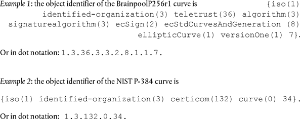
8.2.3Hashing algorithmsU.K.
[F2CSM_49Vehicle units, tachograph cards and external GNSS facilities shall support the SHA-256, SHA-384 and SHA-512 algorithms specified in [SHS].]U.K.
8.2.4Cipher SuitesU.K.
CSM_50In case a symmetric algorithm, an asymmetric algorithm and/or a hashing algorithm are used together to form a security protocol, their respective key lengths and hash sizes shall be of (roughly) equal strength. Table 2 shows the allowed cipher suites:U.K.
| Table 2 | ||||
| Allowed cipher suites | ||||
| Cipher suite Id | ECC key size (bits) | AES key length (bits) | Hashing algorithm | MAC length (bytes) |
|---|---|---|---|---|
| CS#1 | 256 | 128 | SHA-256 | 8 |
| CS#2 | 384 | 192 | SHA-384 | 12 |
| CS#3 | 512/521 | 256 | SHA-512 | 16 |
Note: ECC keys sizes of 512 bits and 521 bits are considered to be equal in strength for all purposes within this Appendix.U.K.
9.KEYS AND CERTIFICATESU.K.
9.1.Asymmetric Key Pairs and Public Key CertificatesU.K.
9.1.1GeneralU.K.
Note: the keys described in this section are used for mutual authentication and secure messaging between vehicle units and tachograph cards and between vehicle units and external GNSS facilities. These processes are described in detail in chapters 10 and 11 of this Appendix.U.K.
CSM_51Within the European Smart Tachograph system, ECC key pairs and corresponding certificates shall be generated and managed through three functional hierarchical levels:U.K.
European level,
Member State level,
Equipment level.
CSM_52Within the entire European Smart Tachograph system, public and private keys and certificates shall be generated, managed and communicated using standardized and secure methods.U.K.
9.1.2European LevelU.K.
CSM_53At European level, a single unique ECC key pair designated as EUR shall be generated. It shall consist of a private key (EUR.SK) and a public key (EUR.PK). This key pair shall form the root key pair of the entire European Smart Tachograph PKI. This task shall be handled by a European Root Certificate Authority (ERCA), under the authority and responsibility of the European Commission.U.K.
CSM_54The ERCA shall use the European private key to sign a (self-signed) root certificate of the European public key, and shall communicate this European root certificate to all Member States.U.K.
CSM_55The ERCA shall use the European private key to sign the certificates of the Member States public keys upon request. The ERCA shall keep records of all signed Member State public key certificates.U.K.
CSM_56As shown in Figure 1 in section 9.1.7, the ERCA shall generate a new European root key pair every 17 years. Whenever the ERCA generates a new European root key pair, it shall create a new self-signed root certificate for the new European public key. The validity period of a European root certificate shall be 34 years plus 3 months.U.K.
Note: The introduction of a new root key pair also implies that ERCA will generate a new motion sensor master key and a new DSRC master key, see sections 9.2.1.2 and 9.2.2.2.U.K.
CSM_57Before generating a new European root key pair, the ERCA shall conduct an analysis of the cryptographic strength that is needed for the new key pair, given it should stay secure for the next 34 years. If found necessary, the ERCA shall switch to a cipher suite that is stronger than the current one, as specified in CSM_50.U.K.
[F2CSM_58 Whenever it generates a new European root key pair, the ERCA shall create a link certificate for the new European public key and sign it with the previous European private key. The validity period of the link certificate shall be 17 years plus 3 months. This is shown in Figure 1 in section 9.1.7 as well.] U.K.
Note: Since a link certificate contains the ERCA generation X public key and is signed with the ERCA generation X-1 private key, a link certificate offers equipment issued under generation X-1 a method to trust equipment issued under generation X.U.K.
CSM_59The ERCA shall not use the private key of a root key pair for any purpose after the moment a new root key certificate becomes valid.U.K.
CSM_60At any moment in time, the ERCA shall dispose of the following cryptographic keys and certificates:U.K.
The current EUR key pair and corresponding certificate
All previous EUR certificates to be used for the verification of MSCA certificates that are still valid
Link certificates for all generations of EUR certificates except the first one
9.1.3Member State LevelU.K.
CSM_61At Member State level, all Member States required to sign tachograph card certificates shall generate one or more unique ECC key pairs designated as MSCA_Card. All Member States required to sign certificates for vehicle units or external GNSS facilities shall additionally generate one or more unique ECC key pairs designated as MSCA_VU-EGF.U.K.
CSM_62The task of generating Member State key pairs shall be handled by a Member State Certificate Authority (MSCA). Whenever a MSCA generates a Member State key pair, it shall send the public key to the ERCA in order to obtain a corresponding Member State certificate signed by the ERCA.U.K.
CSM_63An MSCA shall choose the strength of a Member State key pair equal to the strength of the European root key pair used to sign the corresponding Member State certificate.U.K.
CSM_64An MSCA_VU-EGF key pair, if present, shall consist of private key MSCA_VU-EGF.SK and public key MSCA_VU-EGF.PK. An MSCA shall use the MSCA_VU-EGF.SK private key exclusively to sign the public key certificates of vehicle units and external GNSS facilities.U.K.
CSM_65An MSCA_Card key pair shall consist of private key MSCA_Card.SK and public key MSCA_Card.PK. An MSCA shall use the MSCA_Card.SK private key exclusively to sign the public key certificates of tachograph cards.U.K.
CSM_66An MSCA shall keep records of all signed VU certificates, external GNSS facility certificates and card certificates, together with the identification of the equipment for which each certificate is intended.U.K.
CSM_67The validity period of an MSCA_VU-EGF certificate shall be 17 years plus 3 months. The validity period of an MSCA_Card certificate shall be 7 years plus 1 month.U.K.
CSM_68As shown in Figure 1 in section 9.1.7, the private key of a MSCA_VU-EGF key pair and the private key of a MSCA_Card key pair shall have a key usage period of two years.U.K.
CSM_69An MSCA shall not use the private key of an MSCA_VU-EGF key pair for any purpose after the moment its usage period has ended. Neither shall an MSCA use the private key of an MSCA_Card key pair for any purpose after the moment its usage period has ended.U.K.
CSM_70At any moment in time, an MSCA shall dispose of the following cryptographic keys and certificates:U.K.
The current MSCA_Card key pair and corresponding certificate
All previous MSCA_Card certificates to be used for the verification of the certificates of tachograph cards that are still valid
The current EUR certificate necessary for the verification of the current MSCA certificate
All previous EUR certificates necessary for the verification of all MSCA certificates that are still valid
CSM_71If an MSCA is required to sign certificates for vehicle units or external GNSS facilities, it shall additionally dispose of the following keys and certificates:U.K.
The current MSCA_VU-EGF key pair and corresponding certificate
All previous MSCA_VU-EGF public keys to be used for the verification of the certificates of VUs or external GNSS facilities that are still valid
9.1.4Equipment Level: Vehicle UnitsU.K.
[F2CSM_72Two unique ECC key pairs shall be generated for each vehicle unit, designated as VU_MA and VU_Sign. This task is handled by VU manufacturers. Whenever a VU key pair is generated, the party generating the key shall send the public key to its MSCA, in order to obtain a corresponding VU certificate signed by the MSCA. The private key shall be used only by the vehicle unit.]U.K.
CSM_73The VU_MA and VU_Sign certificates of a given vehicle unit shall have the same Certificate Effective Date.U.K.
CSM_74A VU manufacturer shall choose the strength of a VU key pair equal to the strength of the MSCA key pair used to sign the corresponding VU certificate.U.K.
CSM_75A vehicle unit shall use its VU_MA key pair, consisting of private key VU_MA.SK and public key VU_MA.PK, exclusively to perform VU Authentication towards tachograph cards and external GNSS facilities, as specified in sections 10.3 and 11.4 of this Appendix.U.K.
CSM_76A vehicle unit shall be capable of generating ephemeral ECC key pairs and shall use an ephemeral key pair exclusively to perform session key agreement with a tachograph card or external GNSS facility, as specified in sections 10.4 and 11.4 of this Appendix.U.K.
CSM_77A vehicle unit shall use the private key VU_Sign.SK of its VU_Sign key pair exclusively to sign downloaded data files, as specified in chapter 14 of this Appendix. The corresponding public key VU_Sign.PK shall be used exclusively to verify signatures created by the vehicle unit.U.K.
CSM_78As shown in Figure 1 in section 9.1.7, the validity period of a VU_MA certificate shall be 15 years and 3 months. The validity period of a VU_Sign certificate shall also be 15 years and 3 months.U.K.
Notes:U.K.
—The extended validity period of a VU_Sign certificate allows a Vehicle Unit to create valid signatures over downloaded data during the first three months after it has expired, as required in Regulation (EU) No 581/2010.U.K.
—The extended validity period of a VU_MA certificate is needed to allow the VU to authenticate to a control card or a company card during the first three months after it has expired, such that is it possible to perform a data download.U.K.
CSM_79A vehicle unit shall not use the private key of a VU key pair for any purpose after the corresponding certificate has expired.U.K.
CSM_80The VU key pairs (except ephemeral keys pairs) and corresponding certificates of a given vehicle unit shall not be replaced or renewed in the field once the vehicle unit has been put in operation.U.K.
Notes:U.K.
—Ephemeral key pairs are not included in this requirement, as a new ephemeral key pair is generated by a VU each time Chip Authentication and session key agreement is performed, see section 10.4. Note that ephemeral key pairs do not have corresponding certificates.U.K.
—This requirement does not forbid the possibility of replacing static VU key pairs during a refurbishment or repair in a secure environment controlled by the VU manufacturer.U.K.
CSM_81When put in operation, vehicle units shall contain the following cryptographic keys and certificates:U.K.
The VU_MA private key and corresponding certificate
The VU_Sign private key and corresponding certificate
The MSCA_VU-EGF certificate containing the MSCA_VU-EGF.PK public key to be used for verification of the VU_MA certificate and VU_Sign certificate
The EUR certificate containing the EUR.PK public key to be used for verification of the MSCA_VU-EGF certificate
The EUR certificate whose validity period directly precedes the validity period of the EUR certificate to be used to verify the MSCA_VU-EGF certificate, if existing
The link certificate linking these two EUR certificates, if existing
CSM_82In addition to the cryptographic keys and certificates listed in CSM_81, vehicle units shall also contain the keys and certificates specified in Part A of this Appendix, allowing a vehicle unit to interact with first-generation tachograph cards.U.K.
9.1.5Equipment Level: Tachograph CardsU.K.
[F2CSM_83One unique ECC key pair, designated as Card_MA, shall be generated for each tachograph card. A second unique ECC key pair, designated as Card_Sign, shall additionally be generated for each driver card and each workshop card. This task may be handled by card manufacturers or card personalisers. Whenever a card key pair is generated, the party generating the key shall send the public key to its MSCA, in order to obtain a corresponding card certificate signed by the MSCA. The private key shall be used only by the tachograph card.]U.K.
CSM_84The Card_MA and Card_Sign certificates of a given driver card or workshop card shall have the same Certificate Effective Date.U.K.
CSM_85A card manufacturer or card personaliser shall choose the strength of a card key pair equal to the strength of the MSCA key pair used to sign the corresponding card certificate.U.K.
CSM_86A tachograph card shall use its Card_MA key pair, consisting of private key Card_MA.SK and public key Card_MA.PK, exclusively to perform mutual authentication and session key agreement towards vehicle units, as specified in sections 10.3 and 10.4 of this Appendix.U.K.
CSM_87A driver card or workshop card shall use the private key Card_Sign.SK of its Card_Sign key pair exclusively to sign downloaded data files, as specified in chapter 14 of this Appendix. The corresponding public key Card_Sign.PK shall be used exclusively to verify signatures created by the card.U.K.
[F2CSM_88 The validity period of a Card_MA certificate shall be as follows: U.K.
For driver cards: 5 years
For company cards: 5 years
For control cards: 2 years
For workshop cards: 1 year]
CSM_89The validity period of a Card_Sign certificate shall be as follows:U.K.
Note: the extended validity period of a Card_Sign certificate allows a driver card to create valid signatures over downloaded data during the first month after it has expired. This is necessary in view of Regulation (EU) No 581/2010, which requires that a data download from a driver card must be possible up to 28 days after the last data has been recorded.U.K.
CSM_90The key pairs and corresponding certificates of a given tachograph card shall not be replaced or renewed once the card has been issued.U.K.
CSM_91When issued, tachograph cards shall contain the following cryptographic keys and certificates:U.K.
The Card_MA private key and corresponding certificate
For driver cards and workshop cards additionally: the Card_Sign private key and corresponding certificate
The MSCA_Card certificate containing the MSCA_Card.PK public key to be used for verification of the Card_MA certificate and Card_Sign certificate
The EUR certificate containing the EUR.PK public key to be used for verification of the MSCA_Card certificate.
The EUR certificate whose validity period directly precedes the validity period of the EUR certificate to be used to verify the MSCA_Card certificate, if existing.
The link certificate linking these two EUR certificates, if existing.
[F12Additionally, for control cards, company cards and workshop cards only, and only if such cards are issued during the first three months of the validity period of a new EUR certificate: the EUR certificate that is two generations older, if existing.
Note to last bullet: For example, in the first three months of the ERCA(3) certificate (see Figure 1), the mentioned cards shall contain the ERCA(1) certificate. This is needed to ensure that these cards can be used to perform data downloads from ERCA(1) VUs whose normal 15-year life period plus the 3-months data downloading period expires during these months; see the last bullet of requirement 13) in Annex IC.]U.K.
CSM_92In addition to the cryptographic keys and certificates listed in CSM_91, tachograph cards shall also contain the keys and certificates specified in Part A of this Appendix, allowing these cards to interact with first-generation VUs.U.K.
9.1.6Equipment Level: External GNSS FacilitiesU.K.
[F2CSM_93One unique ECC key pair shall be generated for each external GNSS facility, designated as EGF_MA. This task is handled by external GNSS facility manufacturers. Whenever an EGF_MA key pair is generated, the party generating th e key shall send the public key to its MSCA in order to obtain a corresponding EGF_MA certificate signed by the MSCA. The private key shall be used only by the external GNSS facility.]U.K.
CSM_94An EGF manufacturer shall choose the strength of an EGF_MA key pair equal to the strength of the MSCA key pair used to sign the corresponding EGF_MA certificate.U.K.
[F2CSM_95An external GNSS facility shall use its EGF_MA key pair, consisting of private key EGF_MA.SK and public key EGF_MA.PK, exclusively to perform mutual authentication and session key agreement towards vehicle units, as specified in section 11.4 of this Appendix.]U.K.
CSM_96The validity period of an EGF_MA certificate shall be 15 years.U.K.
CSM_97An external GNSS facility shall not use the private key of its EGF_MA key pair for coupling to a vehicle unit after the corresponding certificate has expired.U.K.
Note: as explained in section 11.3.3, an EGF may potentially use its private key for mutual authentication towards the VU it is already coupled to, even after the corresponding certificate has expired.U.K.
CSM_98The EGF_MA key pair and corresponding certificate of a given external GNSS facility shall not be replaced or renewed in the field once the EGF has been put in operation.U.K.
Note: This requirement does not forbid the possibility of replacing EGF key pairs during a refurbishment or repair in a secure environment controlled by the EGF manufacturer.U.K.
CSM_99When put in operation, an external GNSS facility shall contain the following cryptographic keys and certificates:U.K.
The EGF_MA private key and corresponding certificate
The MSCA_VU-EGF certificate containing the MSCA_VU-EGF.PK public key to be used for verification of the EGF_MA certificate
The EUR certificate containing the EUR.PK public key to be used for verification of the MSCA_VU-EGF certificate
The EUR certificate whose validity period directly precedes the validity period of the EUR certificate to be used to verify the MSCA_VU-EGF certificate, if existing
The link certificate linking these two EUR certificates, if existing
9.1.7Overview: Certificate ReplacementU.K.
Figure 1 below shows how different generations of ERCA root certificates, ERCA link certificates, MSCA certificates and equipment (VU and card) certificates are issued and used over time:
[F2Figure 1 Issuance and usage of different generations of ERCA root certificates, ERCA link certificates, MSCA certificates and equipment certificates] U.K.
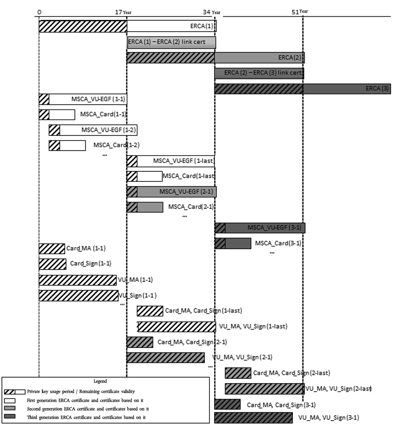
Notes to Figure 1:U.K.
1.Different generations of the root certificate are indicated by a number in brackets. E.g. ERCA (1) is the first generation of ERCA root certificate; ERCA (2) is the second generation, etc.U.K.
2.Other certificates are indicated by two numbers in brackets, the first one indicating the root certificate generation under which they are issued, the second one the generation of the certificate itself. E.g. MSCA_Card (1-1) is the first MSCA_Card certificate issued under ERCA (1); MSCA_Card (2-1) is the first MSCA_Card certificate issued under ERCA (2); MSCA_Card (2-last) is the last MSCA_Card certificate issued under ERCA (2); Card_MA(2-1) is the first Card certificate for mutual authentication that is issued under ERCA (2), etc.U.K.
3.The MSCA_Card (2-1) and MSCA_Card (1-last) certificates are issued at almost but not exactly the same date. MSCA_Card (2-1) is the first MSCA_Card certificate issued under ERCA (2) and will be issued slightly later than MSCA_Card (1-last), the last MSCA_Card certificate under ERCA (1).U.K.
4.As shown in the figure, the first VU and Card certificates issued under ERCA (2) will appear almost two years before the last VU and Card certificates issued under ERCA (1) will appear. This is because of the fact that VU and Card certificates are issued under an MSCA certificate, not directly under the ERCA certificate. The MSCA (2-1) certificate will be issued directly after ERCA (2) becomes valid, but the MSCA (1-last) certificate will be issued only slightly before that time, at the last moment the ERCA (1) certificate is still valid. Therefore, these two MSCA certificates will have almost the same validity period, despite the fact that they are of different generations.U.K.
5.The validity period shown for cards is the one for driver cards (5 years).U.K.
[F26.To save space, the difference in validity period between the Card_MA and Card_Sign certificates is shown only for the first generation.]U.K.
9.2.Symmetric KeysU.K.
9.2.1Keys for Securing VU — Motion Sensor CommunicationU.K.
9.2.1.1GeneralU.K.
Note: readers of this section are supposed to be familiar with the contents of [ISO 16844-3] describing the interface between a vehicle unit and a motion sensor. The pairing process between a VU and a motion sensor is described in detail in chapter 12 of this Appendix.U.K.
CSM_100A number of symmetric keys is needed for pairing vehicle units and motion sensors, for mutual authentication between vehicle units and motion sensors and for encrypting communication between vehicle units and motion sensors, as shown in Table 3. All of these keys shall be AES keys, with a key length equal to the length of the motion sensor master key, which shall be linked to the length of the (foreseen) European root key pair as described in CSM_50.U.K.
| Table 3 | ||||
| Keys for securing vehicle unit — motion sensor communication | ||||
a Storage of KM and KID is optional, as these keys can be derived from KM-VU, KM-WC and CV. | ||||
| Key | Symbol | Generated by | Generation method | Stored by |
|---|---|---|---|---|
| Motion Sensor Master Key — VU part | KM-VU | ERCA | Random | ERCA, MSCAs involved in issuing VUs certificates, VU manufacturers, vehicle units |
| Motion Sensor Master Key — Workshop part | KM-WC | ERCA | Random | ERCA, MSCAs, card manufacturers, workshop cards |
| Motion Sensor Master Key | KM | Not independently generated | Calculated as KM = KM-VU XOR KM-WC | ERCA, MSCAs involved in issuing motion sensors keys (optionally)a |
| Identification Key | KID | Not independently generated | Calculated as KID = KM XOR CV, where CV is specified in CSM_106 | ERCA, MSCAs involved in issuing motion sensors keys (optionally)a |
| Pairing Key | KP | Motion sensor manufacturer | Random | One motion sensor |
| Session Key | KS | VU (during pairing of VU and motion sensor) | Random | One VU and one motion sensor |
CSM_101The European Root Certificate Authority shall generate KM-VU and KM-WC, two random and unique AES keys from which the motion sensor master key KM can be calculated as KM-VU XOR KM-WC. The ERCA shall communicate KM, KM-VU and KM-WC to Member State Certificate Authorities upon their request.U.K.
CSM_102The ERCA shall assign to each motion sensor master key KM a unique version number, which shall also be applicable for the constituting keys KM-VU and KM-WC and for the related identification key KID. The ERCA shall inform the MSCAs about the version number when sending KM-VU and KM-WC to them.U.K.
Note: The version number is used to distinguish different generations of these keys, as explained in detail in section 9.2.1.2.U.K.
CSM_103A Member State Certificate Authority shall forward KM-VU, together with its version number, to vehicle unit manufacturers upon their request. The VU manufacturers shall insert KM-VU and its version number in all manufactured VUs.U.K.
CSM_104A Member State Certificate Authority shall ensure that KM-WC, together with its version number, is inserted in every workshop card issued under its responsibility.U.K.
Notes:U.K.
—See the description of data type  in Appendix 2.U.K.
—as explained in section 9.2.1.2, in fact multiple generations of KM-WC may have to be inserted in a single workshop card.U.K.
CSM_105In addition to the AES key specified in CSM_104, a MSCA shall ensure that the TDES key KmWC, specified in requirement CSM_037 in Part A of this Appendix, is inserted in every workshop card issued under its responsibility.U.K.
Notes:U.K.
—This allows a second-generation workshop card to be used for coupling a first-generation VU.U.K.
—A second-generation workshop card will contain two different applications, one complying with Part B of this Appendix and one complying with Part A. The latter will contain the TDES key KmWC.U.K.
CSM_106An MSCA involved in issuing motion sensors shall derive the identification key from the motion sensor master key by XORing it with a constant vector CV. The value of CV shall be as follows:U.K.
[F2For 128-bit motion sensor master keys: CV = ‘B6 44 2C 45 0E F8 D3 62 0B 7A 8A 97 91 E4 5D 83’]
For 192-bit motion sensor master keys: CV = ‘72 AD EA FA 00 BB F4 EE F4 99 15 70 5B 7E EE BB 1C 54 ED 46 8B 0E F8 25’
For 256-bit motion sensor master keys: CV = ‘1D 74 DB F0 34 C7 37 2F 65 55 DE D5 DC D1 9A C3 23 D6 A6 25 64 CD BE 2D 42 0D 85 D2 32 63 AD 60’
Note: the constant vectors have been generated as follows:U.K.
Pi_10 = first 10 bytes of the decimal portion of the mathematical constant π = ‘24 3F 6A 88 85 A3 08 D3 13 19’
CV_128-bits = first 16 bytes of SHA-256(Pi_10)
CV_192-bits = first 24 bytes of SHA-384(Pi_10)
CV_256-bits = first 32 bytes of SHA-512(Pi_10)
CSM_107 [F2Each Motion sensor manufacturer shall generate a random and unique pairing key K P for every motion sensor, and shall send each pairing key to its Member State Certificate Authority. The MSCA shall encrypt each pairing key separately with the motion sensor master key K M and shall return the encrypted key to the motion sensor manufacturer. For each encrypted key, the MSCA shall notify the motion sensor manufacturer of the version number of the associated K M .] U.K.
Note: as explained in section 9.2.1.2, in fact a motion sensor manufacturer may have to generate multiple unique pairing keys for a single motion sensor.U.K.
[F2CSM_108Each motion sensor manufacturer shall generate a unique serial number for every motion sensor, and shall send all serial numbers to its Member State Certificate Authority. The MSCA shall encrypt each serial number separately with the identification key K ID and shall return the encrypted serial number to the motion sensor manufacturer. For each encrypted serial number, the MSCA shall notify the motion sensor manufacturer of the version number of the associated K ID .]U.K.
CSM_109For requirements CSM_107 and CSM_108, the MSCA shall use the AES algorithm in the Cipher Block Chaining mode of operation, as defined in [ISO 10116], with an interleave parameter m = 1 and an initialization vector SV = ‘00’ {16}, i.e. sixteen bytes with binary value 0. When necessary, the MSCA shall use padding method 2 defined in [ISO 9797-1].U.K.
CSM_110The motion sensor manufacturer shall store the encrypted pairing key and the encrypted serial number in the intended motion sensor, together with the corresponding plain text values and the version number of KM and KID used for encrypting.U.K.
Note: as explained in section 9.2.1.2, in fact a motion sensor manufacturer may have to insert multiple encrypted pairing keys and multiple encrypted serial numbers in a single motion sensor.U.K.
CSM_111In addition to the AES-based cryptographic material specified in CSM_110, a motion sensor manufacturer may also store in each motion sensor the TDES-based cryptographic material specified in requirement CSM_037 in Part A of this Appendix.U.K.
Note: doing so will allow a second-generation motion sensor to be coupled to a first-generation VU.U.K.
CSM_112The length of the session key KS generated by a VU during the pairing to a motion sensor shall be linked to the length of its KM-VU, as described in CSM_50.U.K.
9.2.1.2Motion Sensor Master Key Replacement in Second-Generation EquipmentU.K.
CSM_113Each motion sensor master key and all related keys (see Table 3) is associated to a particular generation of the ERCA root key pair. These keys shall therefore be replaced every 17 years. The validity period of each motion sensor master key generation shall begin one year before the associated ERCA root key pair becomes valid and shall end when the associated ERCA root key pair expires. This is depicted in Figure 2.U.K.
Figure 2
Issuance and usage of different generations of the motion sensor master key in vehicle units, motions sensors and workshop cards

CSM_114At least one year before generating a new European root key pair, as described in CSM_56, the ERCA shall generate a new motion sensor master key KM by generating a new KM-VU and KM-WC. The length of the motion sensor master key shall be linked to the foreseen strength of the new European root key pair, according to CSM_50. The ERCA shall communicate the new KM, KM-VU and KM-WC to the MSCAs upon their request, together with their version number.U.K.
CSM_115An MSCA shall ensure that all valid generations of KM-WC are stored in every workshop card issued under its authority, together with their version numbers, as shown in Figure 2.U.K.
Note: this implies that in the last year of the validity period of an ERCA certificate, workshop cards will be issued with three different generations of KM-WC, as shown in Figure 2.U.K.
CSM_116In relation to the process described in CSM_107 and CSM_108 above: An MSCA shall encrypt each pairing key KP it receives from a motion sensor manufacturer separately with each valid generation of the motion sensor master key KM. An MSCA shall also encrypt each serial number it receives from a motion sensor manufacturer separately with each valid generation of the identification key KID. A motion sensor manufacturer shall store all encryptions of the pairing key and all encryptions of the serial number in the intended motion sensor, together with the corresponding plain text values and the version number(s) of KM and KID used for encrypting.U.K.
Note: This implies that in the last year of the validity period of an ERCA certificate, motion sensors will be issued with encrypted data based on three different generations of KM, as shown in Figure 2.U.K.
CSM_117In relation to the process described in CSM_107 above: Since the length of the pairing key KP shall be linked to the length of KM (see CSM_100), a motion sensor manufacturer may have to generate up to three different pairing keys (of different lengths) for one motion sensor, in case subsequent generations of KM have different lengths. In such a case, the manufacturer shall send each pairing key to the MSCA. The MSCA shall ensure that each pairing key is encrypted with the correct generation of the motion sensor master key, i.e. the one having the same length.U.K.
Note: In case the motion sensor manufacturer chooses to generate a TDES-based pairing key for a second-generation motion sensor (see CSM_111), the manufacturer shall indicate to the MSCA that the TDES-based motion sensor master key must be used for encrypting this pairing key. This is because the length of a TDES key may be equal to that of an AES key, so the MSCA cannot judge from the key length alone.U.K.
CSM_118Vehicle unit manufacturers shall insert only one generation of KM-VU in each vehicle unit, together with its version number. This KM-VU generation shall be linked to the ERCA certificate upon which the VU's certificates are based.U.K.
Notes:U.K.
—A vehicle unit based on the generation X ERCA certificate shall only contain the generation X KM-VU, even if it is issued after the start of the validity period of the generation X+1 ERCA certificate. This is shown in Figure 2.U.K.
—A VU of generation X cannot be paired to a motion sensor of generation X-1.U.K.
—Since workshop cards have a validity period of one year, the result of CSM_113 — CSM_118 is that all workshop cards will contain the new KM-WC at the moment the first VU containing the new KM-VU is issued. Therefore, such a VU will always be able to calculate the new KM. Moreover, by that time most new motion sensors will contain encrypted data based on the new KM as well.U.K.
9.2.2Keys for Securing DSRC CommunicationU.K.
9.2.2.1GeneralU.K.
CSM_119The authenticity and confidentiality of data communicated from a vehicle unit to a control authority over a DSRC remote communication channel shall be ensured by means of a set of VU-specific AES keys derived from a single DSRC master key, KMDSRC.U.K.
CSM_120The DSRC master key KMDSRC shall be an AES key that is securely generated, stored and distributed by the ERCA. The key length may be 128, 192 or 256 bits and shall be linked to the length of the European root key pair, as described in CSM_50.U.K.
CSM_121The ERCA shall communicate the DSRC master key to Member State Certificate Authorities upon their request in a secure manner, to allow them to derive VU-specific DSRC keys and to ensure that the DSRC master key is inserted in all control cards and workshop cards issued under their responsibility.U.K.
CSM_122The ERCA shall assign to each DSRC master key a unique version number. The ERCA shall inform the MSCAs about the version number when sending the DSRC master key to them.U.K.
Note: The version number is used to distinguish different generations of the DSRC master key, as explained in detail in section 9.2.2.2.U.K.
[F2CSM_123 For every vehicle unit, the vehicle unit manufacturer shall create a unique VU serial number and shall send this number to its Member State Certificate Authority in a request to obtain a set of two VU-specific DSRC keys. The VU serial number shall have data type  . U.K.
Note: U.K.
This VU serial number shall be identical to the vuSerialNumber element of VuIdentification, see Appendix 1 and to the Certificate Holder Reference in the VU’s certificates.
The VU serial number may not be known at the moment a vehicle unit manufacturer requests the VU-specific DSRC keys. In this case, the VU manufacturer shall send instead the unique certificate request ID it used when requesting the VU’s certificates; see CSM_153. This certificate request ID shall therefore be equal to the Certificate Holder Reference in the VU’s certificates.]
CSM_124Upon receiving a request for VU-specific DSRC keys, the MSCA shall derive two AES keys for the vehicle unit, called K_VUDSRC_ENC and K_VUDSRC_MAC. These VU-specific keys shall have the same length as the DSRC master key. The MSCA shall use the key derivation function defined in [RFC 5869]. The hash function that is necessary to instantiate the HMAC-Hash function shall be linked to the length of the DSRC master key, as described in CSM_50. The key derivation function in [RFC 5869] shall be used as follows:U.K.
Step 1 (Extract):
PRK = HMAC-Hash (salt, IKM) where salt is an empty string ‘’ and IKM is KMDSRC.
Step 2 (Expand):
OKM = T(1), where
T(1) = HMAC-Hash (PRK, T(0) || info || ‘01’) with
T(0) = an empty string (‘’)
[F2info = VU serial number or certificate request ID, as specified in CSM_123]
K_VUDSRC_ENC = first L octets of OKM and
K_VUDSRC_MAC = last L octets of OKM
where L is the required length of K_VUDSRC_ENC and K_VUDSRC_MAC in octets.
CSM_125The MSCA shall distribute K_VUDSRC_ENC and K_VUDSRC_MAC to the VU manufacturer in a secure manner for insertion in the intended vehicle unit.U.K.
CSM_126When issued, a vehicle unit shall have stored K_VUDSRC_ENC and K_VUDSRC_MAC in its secure memory, in order to be able to ensure the integrity, authenticity and confidentiality of data sent over the remote communication channel. A vehicle unit shall also store the version number of the DSRC master key used to derive these VU-specific keys.U.K.
CSM_127When issued, control cards and workshop cards shall have stored KMDSRC in their secure memory, in order to be able to verify the integrity and authenticity of data sent by a VU over the remote communication channel and to decrypt this data. Control cards and workshop cards shall also store the version number of the DSRC master key.U.K.
Note: as explained in section 9.2.2.2, in fact multiple generations of KMDSRC may have to be inserted in a single workshop card or control card.U.K.
[F2CSM_128The MSCA shall keep records of all VU-specific DSRC keys it generated, their version number and the VU serial number or certificate request ID used in deriving them.]U.K.
9.2.2.2DSRC Master Key ReplacementU.K.
CSM_129Each DSRC master key is associated to a particular generation of the ERCA root key pair. The ERCA shall therefore replace the DSRC master key every 17 years. The validity period of each DSRC master key generation shall begin two years before the associated ERCA root key pair becomes valid and shall end when the associated ERCA root key pair expires. This is depicted in Figure 3.U.K.
Figure 3
Issuance and usage of different generations of the DSRC master key in vehicle units, workshop cards and control cards

CSM_130At least two years before generating a new European root key pair, as described in CSM_56, the ERCA shall generate a new DSRC master key. The length of the DSRC key shall be linked to the foreseen strength of the new European root key pair, according to CSM_50. The ERCA shall communicate the new DSRC master key to the MSCAs upon their request, together with its version number.U.K.
CSM_131An MSCA shall ensure that all valid generations of KMDSRC are stored in every control card issued under its authority, together with their version numbers, as shown in Figure 3.U.K.
Note: this implies that in the last two years of the validity period of an ERCA certificate, control cards will be issued with three different generations of KMDSRC, as shown in Figure 3.U.K.
CSM_132An MSCA shall ensure that all generations of KMDSRC that have been valid for at least a year and are still valid, are stored in every workshop card issued under its authority, together with their version numbers, as shown in Figure 3.U.K.
Note: this implies that in the last year of the validity period of an ERCA certificate, workshop cards will be issued with three different generations of KMDSRC, as shown in Figure 3.U.K.
CSM_133Vehicle unit manufacturers shall insert only one set of VU-specific DSRC keys into each vehicle unit, together with its version number. This set of keys shall be derived from the KMDSRC generation linked to the ERCA certificate upon which the VU's certificates are based.U.K.
Notes:U.K.
—This implies that a vehicle unit based on the generation X ERCA certificate shall only contain the generation X K_VUDSRC_ENC and K_VUDSRC_MAC, even if the VU is issued after the start of the validity period of the generation X+1 ERCA certificate. This is shown in Figure 3.U.K.
—Since workshop cards have a validity period of one year and control cards of two years, the result of CSM_131 — CSM_133 is that all workshop cards and control cards will contain the new DSRC master key at the moment the first VU containing VU-specific keys based on that master key will be issued.U.K.
9.3.CertificatesU.K.
9.3.1GeneralU.K.
CSM_134All certificates in the European Smart Tachograph system shall be self-descriptive, card-verifiable (CV) certificates according to [ISO 7816-4] and [ISO 7816-8].U.K.
CSM_135 [F2The Distinguished Encoding Rules (DER) according to [ISO 8825-1] shall be used to encode the data objects within certificates. Table 4 shows the full certificate encoding, including all tag and length bytes.] U.K.
Note: this encoding results in a Tag-Length-Value (TLV) structure as follows:U.K.
Tag
:
The tag is encoded in one or two octets and indicates the content.
Length
:
The length is encoded as an unsigned integer in one, two, or three octets, resulting in a maximum length of 65 535 octets. The minimum number of octets shall be used.
Value
:
The value is encoded in zero or more octets
9.3.2Certificate ContentU.K.
CSM_136All certificates shall have the structure shown in the certificate profile in Table 4.U.K.
| Table 4 | ||||
| Certificate Profile version 1 | ||||
| Field | Field ID | Tag | Length (bytes) | ASN.1 data type(see Appendix 1) |
|---|---|---|---|---|
| ECC Certificate | C | ‘7F 21’ | var | |
| ECC Certificate Body | B | ‘7F 4E’ | var | |
| Certificate Profile Identifier | CPI | ‘5F 29’ | ‘01’ |  |
| Certificate Authority Reference | CAR | ‘42’ | ‘08’ |  |
| Certificate Holder Authorisation | CHA | ‘5F 4C’ | ‘07’ |   |
| Public Key | PK | ‘7F 49’ | var | |
| Domain Parameters | DP | ‘06’ | var |  |
| Public Point | PP | ‘86’ | var |  |
| Certificate Holder Reference | CHR | ‘5F 20’ | ‘08’ |  |
| Certificate Effective Date | CEfD | ‘5F 25’ | ‘04’ |  |
| Certificate Expiration Date | CExD | ‘5F 24’ | ‘04’ |  |
| ECC Certificate Signature | S | ‘5F 37’ | var |  |
Note: the Field ID will be used in later sections of this Appendix to indicate individual fields of a certificate, e.g. X.CAR is the Certificate Authority Reference mentioned in the certificate of user X.U.K.
9.3.2.1Certificate Profile IdentifierU.K.
CSM_137Certificates shall use a Certificate Profile Identifier to indicate the certificate profile used. Version 1, as specified in Table 4, shall be identified by a value of ‘00’.U.K.
9.3.2.2Certificate Authority ReferenceU.K.
CSM_138The Certificate Authority Reference shall be used to identify the public key to be used to verify the certificate signature. The Certificate Authority Reference shall therefore be equal to the Certificate Holder Reference in the certificate of the corresponding certificate authority.U.K.
CSM_139An ERCA root certificate shall be self-signed, i.e., the Certificate Authority Reference and the Certificate Holder Reference in the certificate shall be equal.U.K.
CSM_140For an ERCA link certificate, the Certificate Holder Reference shall be equal to the CHR of the new ERCA root certificate. The Certificate Authority Reference for a link certificate shall be equal to the CHR of the previous ERCA root certificate.U.K.
9.3.2.3Certificate Holder AuthorisationU.K.
[F2CSM_141The Certificate Holder Authorisation shall be used to identify the type of certificate. It consists of the six most significant bytes of the Tachograph Application ID, concatenated with the equipment type, which indicates the type of equipment for which the certificate is intended. In the case of a VU certificate, a driver card certificate or a workshop card certificate, the equipment type is also used to differentiate between a certificate for Mutual Authentication and a certificate for creating digital signatures (see section 9.1 and Appendix 1, data type EquipmentType).]U.K.
9.3.2.4Public KeyU.K.
The Public Key nests two data elements: the standardized domain parameters to be used with the public key in the certificate and the value of the public point.
CSM_142The data element Domain Parameters shall contain one of the object identifiers specified in Table 1 to reference a set of standardized domain parameters.U.K.
CSM_143The data element Public Point shall contain the public point. Elliptic curve public points shall be converted to octet strings as specified in [TR-03111]. The uncompressed encoding format shall be used. When recovering an elliptic curve point from its encoded format, the validations described in [TR-03111] shall always be carried out.U.K.
9.3.2.5Certificate Holder ReferenceU.K.
CSM_144The Certificate Holder Reference is an identifier for the public key provided in the certificate. It shall be used to reference this public key in other certificates.U.K.
CSM_145For card certificates and external GNSS facility certificates, the Certificate Holder Reference shall have the  data type specified in Appendix 1.U.K.
CSM_146For vehicle units, the manufacturer, when requesting a certificate, may or may not know the manufacturer-specific serial number of the VU for which that certificate and the associated private key is intended. In the first case, the Certificate Holder Reference shall have the  data type specified in Appendix 1. In the latter case, the Certificate Holder Reference shall have the
  data type specified in Appendix 1.U.K.
[F12Note: For a card certificate, the value of the CHR shall be equal to the value of the cardExtendedSerialNumber in EF_ICC; see Appendix 2. For an EGF certificate, the value of the CHR shall be equal to the value of the sensorGNSSSerialNumber in EF_ICC; see Appendix 14. For a VU certificate, the value of the CHR shall be equal to the vuSerialNumber element of VuIdentification, see Appendix 1, unless the manufacturer does not know the manufacturer-specific serial number at the time the certificate is requested.]U.K.
CSM_147For ERCA and MSCA certificates, the Certificate Holder Reference shall have the  data type specified in Appendix 1.U.K.
9.3.2.6Certificate Effective DateU.K.
[F2CSM_148The Certificate Effective Date shall indicate the starting date and time of the validity period of the certificate.]U.K.
9.3.2.7Certificate Expiration DateU.K.
CSM_149The Certificate Expiration Date shall indicate the end date and time of the validity period of the certificate.U.K.
9.3.2.8Certificate SignatureU.K.
CSM_150The signature on the certificate shall be created over the encoded certificate body, including the certificate body tag and length. The signature algorithm shall be ECDSA, as specified in [DSS], using the hashing algorithm linked to the key size of the signing authority, as specified in CSM_50. The signature format shall be plain, as specified in [TR-03111].U.K.
9.3.3Requesting CertificatesU.K.
CSM_151 [F2When requesting a certificate, an MSCA shall send the following data to the ERCA:] U.K.
The Certificate Profile Identifier of the requested certificate
The Certificate Authority Reference expected to be used for signing the certificate.
The Public Key to be signed
CSM_152In addition to the data in CSM_151, an MSCA shall send the following data in a certificate request to the ERCA, allowing the ERCA to create the Certificate Holder Reference of the new MSCA certificate:U.K.
The numerical nation code of the Certification Authority (data type
defined in Appendix 1)
The alphanumerical nation code of the Certification Authority (data type
defined in Appendix 1)
The 1-byte serial number to distinguish the different keys of the Certification Authority in the case keys are changed
The two-byte field containing Certification Authority specific additional info
[F2CSM_153 An equipment manufacturer shall send the following data in a certificate request to an MSCA, allowing the MSCA to create the Certificate Holder Reference of the new equipment certificate: U.K.
If known (see CSM_154), a serial number for the equipment, unique for the manufacturer, the equipment's type and the month of manufacturing. Otherwise, a unique certificate request identifier.
The month and the year of equipment manufacturing or of the certificate request.
The manufacturer shall ensure that this data is correct and that the certificate returned by the MSCA is inserted in the intended equipment.]
CSM_154In the case of a VU, the manufacturer, when requesting a certificate, may or may not know the manufacturer-specific serial number of the VU for which that certificate and the associated private key is intended. If known, the VU manufacturer shall send the serial number to the MSCA. If not known, the manufacturer shall uniquely identify each certificate request and send this certificate request serial number to the MSCA. The resulting certificate will then contain the certificate request serial number. After inserting the certificate in a specific VU, the manufacturer shall communicate the connection between the certificate request serial number and the VU identification to the MSCA.U.K.
10.VU- CARD MUTUAL AUTHENTICATION AND SECURE MESSAGINGU.K.
10.1.GeneralU.K.
CSM_155On a high level, secure communication between a vehicle unit and a tachograph card shall be based on the following steps:U.K.
First, each party shall demonstrate to the other that it owns a valid public key certificate, signed by a Member State Certificate Authority. In turn, the MSCA public key certificate must be signed by the European root certificate authority. This step is called certificate chain verification and is specified in detail in section 10.2
Second, the vehicle unit shall demonstrate to the card that it is in possession of the private key corresponding to the public key in the presented certificate. It does so by signing a random number sent by the card. The card verifies the signature over the random number. If this verification is successful, the VU is authenticated. This step is called VU Authentication and is specified in detail in section 10.3.
Third, both parties independently calculate two AES session keys using an asymmetric key agreement algorithm. Using one of these session keys, the card creates a message authentication code (MAC) over some data sent by the VU. The VU verifies the MAC. If this verification is successful, the card is authenticated. This step is called Card Authentication and is specified in detail in section 10.4.
Fourth, the VU and the card shall use the agreed session keys to ensure the confidentiality, integrity and authenticity of all exchanged messages. This is called Secure Messaging and is specified in detail in section 10.5.
CSM_156The mechanism described in CSM_155 shall be triggered by the vehicle unit whenever a card is inserted into one of its card slots.U.K.
10.2.Mutual Certificate Chain VerificationU.K.
10.2.1Card Certificate Chain Verification by VUU.K.
CSM_157 [F2Vehicle units shall use the protocol depicted in Figure 4 for verifying a tachograph card’s certificate chain. For every certificate it reads from the card, the VU shall verify that the Certificate Holder Authorisation (CHA) field is correct: U.K.
The CHA field of the Card certificate shall indicate a card certificate for mutual authentication (see Appendix 1, data type EquipmentType).
The CHA of the Card.CA certificate shall indicate an MSCA.
The CHA of the Card.Link certificate shall indicate the ERCA.]
Notes to Figure 4:U.K.
—The Card certificates and public keys mentioned in the figure are those for mutual authentication. Section 9.1.5 denotes these as Card_MA.U.K.
—The Card.CA certificates and public keys mentioned in the figure are those for signing card certificates and it is indicated in the CAR of the Card certificate. Section 9.1.3 denotes these as MSCA_Card.U.K.
—The Card.CA.EUR certificate mentioned in the figure is the European root certificate that is indicated in the CAR of the Card.CA certificate.U.K.
—The Card.Link certificate mentioned in the figure is the card's link certificate, if present. As specified in section 9.1.2, this is a link certificate for a new European root key pair created by the ERCA and signed by the previous European private key.U.K.
—The Card.Link.EUR certificate is the European root certificate that is indicated in the CAR of the Card.Link certificate.U.K.
CSM_158As depicted in Figure 4, verification of the card's certificate chain shall begin upon card insertion. The vehicle unit shall read the card holder reference ( ) from EF ICC. The VU shall check if it knows the card, i.e., if it has successfully verified the card's certificate chain in the past and stored it for future reference. If it does, and the card certificate is still valid, the process continues with the verification of the VU certificate chain. Otherwise, the VU shall successively read from the card the MSCA_Card certificate to be used for verifying the card certificate, the Card.CA. EUR certificate to be used for verifying the MSCA_Card certificate, and possibly the link certificate, until it finds a certificate it knows or it can verify. If such a certificate is found, the VU shall use that certificate to verify the underlying card certificates it has read from the card. If successful, the process continues with the verification of the VU certificate chain. If not successful, the VU shall ignore the card.U.K.
Note: There are three ways in which the VU may know the Card.CA.EUR certificate:U.K.
the Card.CA.EUR certificate is the same certificate as the VU's own EUR certificate;
the Card.CA.EUR certificate precedes the VU's own EUR certificate and the VU contained this certificate already at issuance (see CSM_81);
the Card.CA.EUR certificate succeeds the VU's own EUR certificate and the VU received a link certificate in the past from another tachograph card, verified it and stored it for future reference.
CSM_159As indicated in Figure 4, once the VU has verified the authenticity and validity of a previously unknown certificate, it may store this certificate for future reference, such that it does not need to verify that certificate's authenticity again if it is presented to the VU again. Instead of storing the entire certificate, a VU may choose to store only the contents of the Certificate Body, as specified in section 9.3.2. [F12Whereas storing of all other types of certificate is optional, it is mandatory for a VU to store a new link certificate presented by a card.]U.K.
CSM_160The VU shall verify the temporal validity of any certificate read from the card or stored in its memory, and shall reject expired certificates. For verifying the temporal validity of a certificate presented by the card a VU shall use its internal clock.U.K.

10.2.2VU Certificate Chain Verification by CardU.K.
CSM_161 [F2Tachograph cards shall use the protocol depicted in Figure 5 for verifying a VU's certificate chain. For every certificate presented by the VU, the card shall verify that the Certificate Holder Authorisation (CHA) field is correct: U.K.
The CHA of the VU.Link certificate shall indicate the ERCA.
The CHA of the VU.CA certificate shall indicate an MSCA.
The CHA field of the VU certificate shall indicate a VU certificate for mutual authentication (see Appendix 1, data type EquipmentType).]

Notes to Figure 5:U.K.
—The VU certificates and public keys mentioned in the figure are those for mutual authentication. Section 9.1.4 denotes these as VU_MA.U.K.
—The VU.CA certificates and public keys mentioned in the figure are those for signing VU and external GNSS facility certificates. Section 9.1.3 denotes these as MSCA_VU-EGF.U.K.
—The VU.CA.EUR certificate mentioned in the figure is the European root certificate that is indicated in the CAR of the VU.CA certificate.U.K.
—The VU.Link certificate mentioned in the figure is the VU's link certificate, if present. As specified in section 9.1.2, this is a link certificate for a new European root key pair created by the ERCA and signed by the previous European private key.U.K.
—The VU.Link.EUR certificate is the European root certificate that is indicated in the CAR of the VU.Link certificate.U.K.
CSM_162As depicted in Figure 5, verification of the certificate chain of the vehicle unit shall begin with the vehicle unit attempting to set its own public key for use in the tachograph card. If this succeeds, it means that the card successfully verified the VU's certificate chain in the past, and has stored the VU certificate for future reference. In this case, the VU certificate is set for use and the process continues with VU Authentication. If the card does not know the VU certificate, the VU shall successively present the VU.CA certificate to be used for verifying its VU certificate, the VU.CA.EUR certificate to be used for verifying the VU.CA certificate, and possibly the link certificate, in order to find a certificate known or verifiable by the card. If such a certificate is found, the card shall use that certificate to verify the underlying VU certificates presented to it. If successful, the VU shall finally set its public key for use in the tachograph card. If not successful, the VU shall ignore the card.U.K.
Note: There are three ways in which the card may know the VU.CA.EUR certificate:U.K.
—the VU.CA.EUR certificate is the same certificate as the card's own EUR certificate;U.K.
—the VU.CA.EUR certificate precedes the card's own EUR certificate and the card contained this certificate already at issuance (see CSM_91);U.K.
—the VU.CA.EUR certificate succeeds the card's own EUR certificate and the card received a link certificate in the past from another vehicle unit, verified it and stored it for future reference.U.K.
CSM_163The VU shall use the MSE: Set AT command to set its public key for use in the tachograph card. As specified in Appendix 2, this command contains an indication of the cryptographic mechanism that will be used with the key that is set. This mechanism shall be ‘VU Authentication using the ECDSA algorithm, in combination with the hashing algorithm linked to the key size of the VU's VU_MA key pair, as specified in CSM_50’.U.K.
CSM_164The MSE: Set AT command also contains an indication of the ephemeral key pair which the VU will use during session key agreement (see section 10.4). Therefore, before sending the MSE: Set AT command, the VU shall generate an ephemeral ECC key pair. For generating the ephemeral key pair, the VU shall use the standardized domain parameters indicated in the card certificate. The ephemeral key pair is denoted as (VU.SKeph, VU.PKeph, Card.DP). The VU shall take the x-coordinate of the ECDH ephemeral public point as the key identification; this is called the compressed representation of the public key and denoted as Comp(VU.PKeph).U.K.
[F2CSM_165If the MSE: Set AT command is successful, the card shall set the indicated VU.PK for subsequent use during Vehicle Authentication, and shall temporarily store Comp(VU.PKeph). In case two or more successful MSE: Set AT commands are sent before session key agreement is performed, the card shall store only the last Comp(VU.PKeph) received. The card shall reset Comp(VU.PKeph) after a successful GENERAL AUTHENTICATE command.]U.K.
CSM_166The card shall verify the temporal validity of any certificate presented by the VU or referenced by the VU while stored in the card's memory, and shall reject expired certificates.U.K.
CSM_167For verifying the temporal validity of a certificate presented by the VU, each tachograph card shall internally store some data representing the current time. This data shall not be directly updatable by a VU. At issuance, the current time of a card shall be set equal to the Effective Date of the card's Card_MA certificate. A card shall update its current time if the Effective Date of an authentic ‘valid source of time’ certificate presented by a VU is more recent than the card's current time. In that case, the card shall set its current time to the Effective Date of that certificate. The card shall accept only the following certificates as a valid source of time:U.K.
Second-generation ERCA link certificates
Second-generation MSCA certificates
Second-generation VU certificates issued by the same country as the card's own card certificate(s).
Note: the last requirement implies that a card shall be able to recognize the CAR of the VU certificate, i.e. the MSCA_VU-EGF certificate. This will not be the same as the CAR of its own certificate, which is the MSCA_Card certificate.U.K.
CSM_168As indicated in Figure 5, once the card has verified the authenticity and validity of a previously unknown certificate, it may store this certificate for future reference, such that it does not need to verify that certificate's authenticity again if it is presented to the card again. Instead xof storing the entire certificate, a card may choose to store only the contents of the Certificate Body, as specified in section 9.3.2.U.K.
10.3.VU AuthenticationU.K.
CSM_169Vehicle units and cards shall use the VU Authentication protocol depicted in Figure 6 to authenticate the VU towards the card. VU Authentication enables the tachograph card to explicitly verify that the VU is authentic. To do so, the VU shall use its private key to sign a challenge generated by the card.U.K.
CSM_170 [F2Next to the card challenge, the VU shall include in the signature the certificate holder reference taken from the card certificate.] U.K.
Note: This ensures that the card to which the VU authenticates itself is the same card whose certificate chain the VU has verified previously.U.K.
CSM_171The VU shall also include in the signature the identifier of the ephemeral public key Comp(VU.PKeph) which the VU will use to set up Secure Messaging during the Chip Authentication process specified in section 10.4.U.K.
Note: This ensures that the VU with which a card communicates during a Secure Messaging session is the same VU that was authenticated by the card.U.K.
[F2Figure 6 VU Authentication protocol ]U.K.
CSM_172If multiple GET CHALLENGE commands are sent by the VU during VU Authentication, the card shall return a new 8-byte random challenge each time, but shall store only the last challenge.U.K.
CSM_173The signing algorithm used by the VU for VU Authentication shall be ECDSA as specified in [DSS], using the hashing algorithm linked to the key size of the VU's VU_MA key pair, as specified in CSM_50. The signature format shall be plain, as specified in [TR-03111]. The VU shall send the resulting signature to the card.U.K.
[F2CSM_174 Upon receiving the VU’s signature in an EXTERNAL AUTHENTICATE command, the card shall U.K.
Calculate the authentication token by concatenating Card.CHR, the card challenge rcard and the identifier of the VU ephemeral public key Comp(VU.PKeph),
Verify the VU’s signature using the ECDSA algorithm, using the hashing algorithm linked to the key size of the VU’s VU_MA key pair as specified in CSM_50, in combination with VU.PK and the calculated authentication token.]
10.4.Chip Authentication and Session Key AgreementU.K.
CSM_175Vehicle units and cards shall use the Chip Authentication protocol depicted in Figure 7 to authenticate the card towards the VU. Chip Authentication enables the vehicle unit to explicitly verify that the card is authentic.U.K.

CSM_176The VU and the card shall take the following steps:U.K.
1.
The vehicle unit initiates the Chip Authentication process by sending the MSE: Set AT command indicating ‘Chip Authentication using the ECDH algorithm resulting in an AES session key length linked to the key size of the card's Card_MA key pair, as specified in CSM_50’. The VU shall determine the key size of the card's key pair from the card certificate.
2.
[F2The VU sends the public point VU.PK eph of its ephemeral key pair to the card. The public point shall be converted to an octet string as specified in [TR-03111]. The uncompressed encoding format shall be used. As explained in CSM_164, the VU generated this ephemeral key pair prior to the verification of the VU certificate chain. The VU sent the identifier of the ephemeral public key Comp(VU.PK eph ) to the card, and the card stored it.]
3.
The card computes Comp(VU.PKeph) from VU.PKeph and compares this to the stored value of Comp(VU.PKeph).
4.
Using the ECDH algorithm in combination with the card's static private key and the VU's ephemeral public key, the card computes a secret K.
5.
The card chooses a random 8-byte nonce NPICC and uses it to derive two AES session keys KMAC and KENC from K. See CSM_179.
6.
[F2Using K MAC , the card computes an authentication token over the VU ephemeral public point: T PICC = CMAC(K MAC , VU.PK eph ). The public point shall be in the format used by the VU (see bullet 2 above). The card sends N PICC and T PICC to the vehicle unit.]
7.
Using the ECDH algorithm in combination with the card's static public key and the VU's ephemeral private key, the VU computes the same secret K as the card did in step 4.
8.
The VU derives session keys KMAC and KENC from K and NPICC; see CSM_179.
9.
The VU verifies the authentication token TPICC.
CSM_177In step 3 above, the card shall compute Comp(VU.PKeph) as the x-coordinate of the public point in VU.PKeph.U.K.
CSM_178In steps 4 and 7 above, the card and the vehicle unit shall use the ECKA-EG algorithm as defined in [TR-03111].U.K.
CSM_179In steps 5 and 8 above, the card and the vehicle unit shall use the key derivation function for AES session keys defined in [TR-03111], with the following precisions and changes:U.K.
The value of the counter shall be ‘00 00 00 01’ for KENC and ‘00 00 00 02’ for KMAC.
The optional nonce r shall be used and shall be equal to NPICC.
For deriving 128-bits AES keys, the hashing algorithm to be used shall be SHA-256.
For deriving 192-bits AES keys, the hashing algorithm to be used shall be SHA-384.
For deriving 256-bits AES keys, the hashing algorithm to be used shall be SHA-512.
The length of the session keys (i.e. the length at which the hash is truncated) shall be linked to the size of the Card_MA key pair, as specified in CSM_50.
CSM_180In steps 6 and 9 above, the card and the vehicle unit shall use the AES algorithm in CMAC mode, as specified in [SP 800-38B]. The length of TPICC shall be linked to the length of the AES session keys, as specified in CSM_50.U.K.
10.5.Secure MessagingU.K.
10.5.1GeneralU.K.
CSM_181All commands and responses exchanged between a vehicle unit and a tachograph card after successful Chip Authentication took place and until the end of the session shall be protected by Secure Messaging.U.K.
CSM_182Except when reading from a file with access condition SM-R-ENC-MAC-G2 (see Appendix 2, section 4), Secure Messaging shall be used in authentication-only mode. In this mode, a cryptographic checksum (a.k.a. MAC) is added to all commands and responses to ensure message authenticity and integrity.U.K.
CSM_183When reading data from a file with access condition SM-R-ENC-MAC-G2, Secure Messaging shall be used in encrypt-then-authenticate mode, i.e. the response data is encrypted first to ensure message confidentiality, and afterwards a MAC over the formatted encrypted data is calculated to ensure authenticity and integrity.U.K.
CSM_184Secure Messaging shall use AES as defined in [AES] with the session keys KMAC and KENC that were agreed during Chip Authentication.U.K.
CSM_185An unsigned integer shall be used as the Send Sequence Counter (SSC) to prevent replay attacks. The size of the SSC shall be equal to the AES block size, i.e. 128 bits. The SSC shall be in MSB-first format. The Send Sequence Counter shall be initialized to zero (i.e. ‘00 00 00 00 00 00 00 00 00 00 00 00 00 00 00 00’) when Secure Messaging is started. The SSC shall be increased every time before a command or response APDU is generated, i.e. since the starting value of the SSC in a SM session is 0, in the first command the value of the SSC will be 1. The value of SSC for the first response will be 2.U.K.
CSM_186For message encryption, KENC shall be used with AES in the Cipher Block Chaining (CBC) mode of operation, as defined in [ISO 10116], with an interleave parameter m = 1 and an initialization vector SV = E(KENC, SSC), i.e. the current value of the Send Sequence Counter encrypted with KENC.U.K.
CSM_187For message authentication, KMAC shall be used with AES in CMAC mode as specified in [SP 800-38B]. The length of the MAC shall be linked to the length of the AES session keys, as specified in CSM_50. The Send Sequence Counter shall be included in the MAC by prepending it before the datagram to be authenticated.U.K.
10.5.2Secure Message StructureU.K.
CSM_188Secure Messaging shall make use only of the Secure Messaging data objects (see [ISO 7816-4]) listed in Table 5. In any message, these data objects shall be used in the order specified in this table.U.K.
| Table 5 | |||
| Secure Messaging Data Objects | |||
| Data Object Name | Tag | Presence (M)andatory, (C)onditional or (F)orbidden in | |
|---|---|---|---|
| Commands | Responses | ||
| Plain value not encoded in BER-TLV | ‘81’ | C | C |
| Plain value encoded in BER-TLV, but not including SM DOs | ‘B3’ | C | C |
| Padding-content indicator followed by cryptogram, plain value not encoded in BER-TLV | ‘87’ | C | C |
| Protected Le | ‘97’ | C | F |
| Processing Status | ‘99’ | F | M |
| Cryptographic Checksum | ‘8E’ | M | M |
Note: As specified in Appendix 2, tachograph cards may support the READ BINARY and UPDATE BINARY command with an odd INS byte (‘B1’ resp. ‘D7’). These command variants are required to read and update files with more than 32 768 bytes or more. In case such a variant is used, a data object with tag ‘B3’ shall be used instead of an object with tag ‘81’. See Appendix 2 for more information.U.K.
CSM_189All SM data objects shall be encoded in DER TLV as specified in [ISO 8825-1]. This encoding results in a Tag-Length-Value (TLV) structure as follows:U.K.
Tag
:
The tag is encoded in one or two octets and indicates the content.
Length
:
The length is encoded as an unsigned integer in one, two, or three octets, resulting in a maximum length of 65 535 octets. The minimum number of octets shall be used.
Value
:
The value is encoded in zero or more octets
CSM_190APDUs protected by Secure Messaging shall be created as follows:U.K.
The command header shall be included in the MAC calculation, therefore value ‘0C’shall be used for the class byte CLA.
As specified in Appendix 2, all INS bytes shall be even, with the possible exception of odd INS bytes for the READ BINARY and UPDATE BINARY commands.
The actual value of Lc will be modified to Lc' after application of secure messaging.
The Data field shall consist of SM data objects.
In the protected command APDU the new Le byte shall be set to ‘00’. If required, a data object ‘97’ shall be included in the Data field in order to convey the original value of Le.
[F2CSM_191 Any data object to be encrypted shall be padded according to [ISO 7816-4] using padding-content indicator ‘01’. For the calculation of the MAC, data objects in the APDU shall be padded according to [ISO 7816-4]. U.K.
Note: Padding for Secure Messaging is always performed by the secure messaging layer, not by the CMAC or CBC algorithms.U.K.
Summary and Examples U.K.
A command APDU with applied Secure Messaging will have the following structure, depending on the case of the respective unsecured command (DO is data object):
Case 1
:
CLA INS P1 P2 || Lc' || DO ‘8E’ || Le
Case 2
:
CLA INS P1 P2 || Lc' || DO ‘97’ || DO‘8E’ || Le
Case 3 (even INS byte)
:
CLA INS P1 P2 || Lc' || DO ‘81’ || DO‘8E’ || Le
Case 3 (odd INS byte)
:
CLA INS P1 P2 || Lc' || DO ‘B3’ || DO‘8E’ || Le
Case 4 (even INS byte)
:
CLA INS P1 P2 || Lc' || DO ‘81’ || DO‘97’ || DO‘8E’ || Le
Case 4 (odd INS byte)
:
CLA INS P1 P2 || Lc' || DO ‘B3’ || DO‘97’ || DO‘8E’ || Le
where Le = ‘00’ or ‘00 00’ depending on whether short length fields or extended length fields are used; see [ISO 7816-4].
A response APDU with applied Secure Messaging will have the following structure, depending on the case of the respective unsecured response:
Case 1 or 3
:
DO ‘99’ || DO ‘8E’ || SW1SW2
Case 2 or 4 (even INS byte) without encryption
:
DO ‘81’ || DO ‘99’ || DO ‘8E’ || SW1SW2
Case 2 or 4 (even INS byte) with encryption
:
DO ‘87’ || DO ‘99’ || DO ‘8E’ || SW1SW2
Case 2 or 4 (odd INS byte) without encryption
:
DO ‘B3’ || DO ‘99’ || DO ‘8E’ || SW1SW2
Note: Case 2 or 4 (odd INS byte) with encryption is never used in the communication between a VU and a card.U.K.
Below are three example APDU transformations for commands with even INS code. Figure 8 shows an authenticated Case 4 command APDU, Figure 9 shows an authenticated Case 1/Case 3 response APDU, and Figure 10 shows an encrypted and authenticated Case 2/Case 4 response APDU.

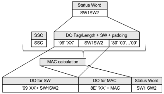
Figure 10 Transformation of an encrypted and authenticated Case 2/Case 4 Response APDU ]U.K.
10.5.3Secure Messaging Session AbortionU.K.
CSM_192A vehicle unit shall abort an ongoing Secure Messaging session if and only if one of the following conditions occur:U.K.
it receives a plain response APDU,
it detects a Secure Messaging error in a response APDU:
An expected Secure Messaging data object is missing, the order of data objects is incorrect, or an unknown data object is included.
A Secure Messaging data object is incorrect, e.g. the MAC value is incorrect, the TLV structure is incorrect or the padding indicator in tag ‘87’ is not equal to ‘01’.
the card sends a status byte indicating it detected an SM error (see CSM_194),
the limit for the number of commands and associated responses within the current session is reached. For a given VU, this limit shall be defined by its manufacturer, taking into account the security requirements of the hardware used, with a maximum value of 240 SM commands and associated responses per session.
[F2CSM_193 A tachograph card shall abort an ongoing Secure Messaging session if and only if one of the following conditions occur: U.K.
it receives a plain command APDU,
it detects a Secure Messaging error in a command APDU:
An expected Secure Messaging data object is missing, the order of data objects is incorrect, or an unknown data object is included.
A Secure Messaging data object is incorrect, e.g. the MAC value is incorrect or the TLV structure is incorrect.
it is depowered or reset,
the VU starts the VU Authentication process,
the limit for the number of commands and associated responses within the current session is reached. For a given card, this limit shall be defined by its manufacturer, taking into account the security requirements of the hardware used, with a maximum value of 240 SM commands and associated responses per session.]
CSM_194Regarding SM error handling by a tachograph card:U.K.
If in a command APDU some expected Secure Messaging data objects are missing, the order of data objects is incorrect or unknown data objects are included, a tachograph card shall respond with status bytes ‘69 87’.
If a Secure Messaging data object in a command APDU is incorrect, a tachograph card shall respond with status bytes ‘69 88’.
In such a case, the status bytes shall be returned without using SM.
CSM_195If a Secure Messaging session between a VU and a tachograph card is aborted, the VU and the tachograph card shallU.K.
securely destroy the stored session keys
immediately establish a new Secure Messaging session, as described in sections 10.2 — 10.5.
CSM_196If for any reason the VU decides to restart mutual authentication towards an inserted card, the process shall restart with verification of the card certificate chain, as described in section 10.2, and shall continue as described in sections 10.2 — 10.5.U.K.
11.VU — EXTERNAL GNSS FACILITY COUPLING, MUTUAL AUTHENTICATION AND SECURE MESSAGINGU.K.
11.1.GeneralU.K.
CSM_197The GNSS facility used by a VU to determine its position may be internal, (i.e. built into the VU casing and not detachable), or it may be an external module. In the first case, there is no need to standardize the internal communication between the GNSS facility and the VU, and the requirements in this chapter do not apply. In the latter case, communication between the VU and the external GNSS facility shall be standardized and protected as described in this chapter.U.K.
CSM_198Secure communication between a vehicle unit and an external GNSS facility shall take place in the same way as secure communication between a vehicle unit and a tachograph card, with the external GNSS facility (EGF) taking the role of the card. All requirements mentioned in chapter 10 for tachograph cards shall be satisfied by an EGF, taking into account the deviations, clarifications and additions mentioned in this chapter. In particular, mutual certificate chain verification, VU Authentication and Chip Authentication shall be performed as described in sections 11.3 and 11.4.U.K.
CSM_199Communication between a vehicle unit and an EGF differs from communication between a vehicle unit and a card in the fact that a vehicle unit and an EGF must be coupled once in a workshop before the VU and the EGF can exchange GNSS-based data during normal operation. The coupling process is described in section 11.2.U.K.
CSM_200For communication between a vehicle unit and an EGF, APDU commands and responses based on [ISO 7816-4] and [ISO 7816-8] shall be used. The exact structure of these APDUs is defined in Appendix 2 of this Annex.U.K.
11.2.VU and External GNSS Facility CouplingU.K.
CSM_201A vehicle unit and an EGF in a vehicle shall be coupled by a workshop. Only a coupled vehicle unit and EGF shall be able to communicate during normal operation.U.K.
CSM_202Coupling of a vehicle unit and an EGF shall only be possible if the vehicle unit is in calibration mode. The coupling shall be initiated by the vehicle unit.U.K.
CSM_203A workshop may re-couple a vehicle unit to another EGF or to the same EGF at any time. During re-coupling, the VU shall securely destroy the existing EGF_MA certificate in its memory and shall store the EGF_MA certificate of the EGF to which it is being coupled.U.K.
CSM_204A workshop may re-couple an external GNSS facility to another VU or to the same VU at any time. During re-coupling, the EGF shall securely destroy the existing VU_MA certificate in its memory and shall store the VU_MA certificate of the VU to which it is being coupled.U.K.
11.3.Mutual Certificate Chain VerificationU.K.
11.3.1GeneralU.K.
CSM_205Mutual certificate chain verification between a VU and an EGF shall take place only during the coupling of the VU and the EGF by a workshop. During normal operation of a coupled VU and EGF, no certificates shall be verified. Instead, the VU and EGF shall trust the certificates they stored during the coupling, after checking the temporal validity of these certificates. The VU and the EGF shall not trust any other certificates for protecting the VU — EGF communication during normal operation.U.K.
11.3.2During VU — EGF CouplingU.K.
CSM_206During the coupling to an EGF, a vehicle unit shall use the protocol depicted in Figure 4 (section 10.2.1) for verifying the external GNSS facility's certificate chain.U.K.
Notes to Figure 4 within this context:U.K.
—Communication control is out of the scope of this Appendix. However, an EGF is not a smart card and hence the VU will probably not send a Reset to initiate the communication and will not receive an ATR.U.K.
—The Card certificates and public keys mentioned in the figure shall be interpreted as the EGF's certificates and public keys for mutual authentication. Section 9.1.6 denotes these as EGF_MA.U.K.
—The Card.CA certificates and public keys mentioned in the figure shall be interpreted as the MSCA's certificates and public keys for signing EGF certificates. Section 9.1.3 denotes these as MSCA_VU-EGF.U.K.
—The Card.CA.EUR certificate mentioned in the figure shall be interpreted as the European root certificate that is indicated in the CAR of the MSCA_VU-EGF certificate.U.K.
—The Card.Link certificate mentioned in the figure shall be interpreted as the EGF's link certificate, if present. As specified in section 9.1.2, this is a link certificate for a new European root key pair created by the ERCA and signed by the previous European private key.U.K.
—The Card.Link.EUR certificate is the European root certificate that is indicated in the CAR of the Card.Link certificate.U.K.
—Instead of the  , the VU shall read the
  from EF ICC.U.K.
—Instead of selecting the Tachograph AID, the VU shall select the EGF AID.U.K.
—‘Ignore Card’ shall be interpreted as ‘Ignore EGF’.U.K.
CSM_207Once it has verified the EGF_MA certificate, the vehicle unit shall store this certificate for use during normal operation; see section 11.3.3.U.K.
CSM_208 [F2During the coupling to a VU, an external GNSS facility shall use the protocol depicted in Figure 5 (section 10.2.2) for verifying the VU's certificate chain.] U.K.
Notes to Figure 5 within this context:U.K.
—The VU shall generate a fresh ephemeral key pair using the domain parameters in the EGF certificate.U.K.
—The VU certificates and public keys mentioned in the figure are those for mutual authentication. Section 9.1.4 denotes these as VU_MA.U.K.
—The VU.CA certificates and public keys mentioned in the figure are those for signing VU and external GNSS facility certificates. Section 9.1.3 denotes these as MSCA_VU-EGF.U.K.
—The VU.CA.EUR certificate mentioned in the figure is the European root certificate that is indicated in the CAR of the VU.CA certificate.U.K.
—The VU.Link certificate mentioned in the figure is the VU's link certificate, if present. As specified in section 9.1.2, this is a link certificate for a new European root key pair created by the ERCA and signed by the previous European private key.U.K.
—The VU.Link.EUR certificate is the European root certificate that is indicated in the CAR of the VU.Link certificate.U.K.
CSM_209In deviation from requirement CSM_167, an EGF shall use the GNSS time to verify the temporal validity of any certificate presented.U.K.
[F2CSM_210Once it has verified the VU_MA certificate, the external GNSS facility shall store this certificate for use during normal operation; see section 11.3.3.]U.K.
11.3.3During Normal OperationU.K.
CSM_211 [F2During normal operation, a vehicle unit and an EGF shall use the protocol depicted in Figure 11 for verifying the temporal validity of the stored EGF_MA certificate and for setting the VU_MA public key for subsequent VU Authentication. No further mutual verification of the certificate chains shall take place during normal operation.] U.K.
Note that Figure 11 in essence consists of the first steps shown in Figure 4 and Figure 5. Again, note that since an EGF is not a smart card, the VU will probably not send a Reset to initiate the communication and will not receive an ATR. In any case this is out of the scope of this Appendix.U.K.

CSM_212As shown in Figure 11, the vehicle unit shall log an error if the EGF_MA certificate is no longer valid. However, mutual authentication, key agreement and subsequent communication via secure messaging shall proceed normally.U.K.
11.4.VU Authentication, Chip Authentication and Session Key AgreementU.K.
CSM_213VU Authentication, Chip Authentication and session key agreement between a VU and an EGF shall take place during coupling and whenever a Secure Messaging session is re-established during normal operation. The VU and the EGF shall carry out the processes described in sections 10.3 and 10.4. All requirements in these sections shall apply.U.K.
11.5.Secure MessagingU.K.
CSM_214All commands and responses exchanged between a vehicle unit and an external GNSS facility after successful Chip Authentication took place and until the end of the session shall be protected by Secure Messaging.in authentication-only mode. All requirements in section 10.5 shall apply.U.K.
CSM_215If a Secure Messaging session between a VU and an EGF is aborted, the VU shall immediately establish a new Secure Messaging session, as described in section 11.3.3 and 11.4.U.K.
12.VU — MOTION SENSOR PAIRING AND COMMUNICATIONU.K.
12.1.GeneralU.K.
CSM_216A vehicle unit and a motion sensor shall communicate using the interface protocol specified in [ISO 16844-3] during pairing and in normal operation, with the changes described in this chapter and in section 9.2.1.U.K.
Note: readers of this chapter are supposed to be familiar with the contents of [ISO 16844-3].U.K.
12.2.VU — Motion Sensor Pairing Using Different Key GenerationsU.K.
As explained in section 9.2.1, the motion sensor master key and all associated keys are regularly replaced. This leads to the presence of up to three motion sensor-related AES keys KM-WC (of consecutive key generations) in workshop cards. Similarly, in motion sensors up to three different AES-based encryptions of data (based on consecutive generations of the motion sensor master key KM) may be present. A vehicle unit contains only one motion sensor-related key KM-VU.
CSM_217A second-generation VU and a second-generation motion sensor shall be paired as follows (compare Table 6 in [ISO 16844-3]):U.K.
1.
A second-generation workshop card is inserted into the VU and the VU is connected to the motion sensor.
2.
The VU reads all available KM-WC keys from the workshop card, inspects their key version numbers and chooses the one matching the version number of the VU's KM-VU key. If the matching KM-WC key is not present on the workshop card, the VU aborts the pairing process and shows an appropriate error message to the workshop card holder.
3.
The VU calculates the motion sensor master key KM from KM-VU and KM-WC, and the identification key KID from KM, as specified in section 9.2.1.
4.
The VU sends the instruction to initiate the pairing process towards the motion sensor, as described in [ISO 16844-3], and encrypts the serial number it receives from the motion sensor with the identification key KID. The VU sends the encrypted serial number back to the motion sensor.
5.
The motion sensor matches the encrypted serial number consecutively with each of the encryptions of the serial number it holds internally. If it finds a match, the VU is authenticated. The motion sensor notes the generation of KID used by the VU and returns the matching encrypted version of its pairing key; i.e. the encryption that was created using the same generation of KM.
6.
The VU decrypts the pairing key using KM, generates a session key KS, encrypts it with the pairing key and sends the result to the motion sensor. The motion sensor decrypts KS.
7.
The VU assembles the pairing information as defined in [ISO 16844-3], encrypts the information with the pairing key, and sends the result to the motion sensor. The motion sensor decrypts the pairing information.
8.
The motion sensor encrypts the received pairing information with the received KS and returns this to the VU. The VU verifies that the pairing information is the same information which the VU sent to the motion sensor in the previous step. If it is, this proves that the motion sensor used the same KS as the VU and hence in step 5 sent its pairing key encrypted with the correct generation of KM. Hence, the motion sensor is authenticated.
Note that steps 2 and 5 are different from the standard process in [ISO 16844-3]; the other steps are standard.U.K.
Example: Suppose a pairing takes place in the first year of the validity of the ERCA (3) certificate; see Figure 2 in section 9.2.1.2. Moreover
Suppose the motion sensor was issued in the last year of the validity of the ERCA (1) certificate. It will therefore contain the following keys and data:
Ns[1]: its serial number encrypted with generation 1 of KID,
Ns[2]: its serial number encrypted with generation 2 of KID,
Ns[3]: its serial number encrypted with generation 3 of KID,
KP[1]: its generation-1 pairing key(22), encrypted with generation 1 of KM,
KP[2]: its generation-2 pairing key, encrypted with generation 2 of KM,
KP[3]: its generation-3 pairing key, encrypted with generation 3 of KM,
Suppose that the workshop card was issued in the first year of the validity of the ERCA (3) certificate. It will therefore contain the generation 2 and generation 3 of the KM-WC key.
Suppose the VU is a generation-2 VU, containing the generation 2 of KM-VU.
In this case, the following will happen in steps 2 — 5:
Step 2: The VU reads generation 2 and generation 3 of KM-WC from the workshop card and inspects their version numbers.
Step 3: The VU combines the generation-2 KM-WC with its KM-VU to compute KM and KID.
Step 4: The VU encrypts the serial number it receives from the motion sensor with KID.
Step 5: The motion sensor compares the received data with Ns[1] and doesn't find a match. Next, it compares the data with Ns[2] and finds a match. It concludes that the VU is a generation-2 VU, and therefore sends back KP[2].
12.3.VU — Motion Sensor Pairing and Communication using AESU.K.
CSM_218As specified in Table 3 in section 9.2.1, all keys involved in the pairing of a (second-generation) vehicle unit and a motion sensor and in subsequent communication shall be AES keys, rather than double-length TDES keys as specified in [ISO 16844-3]. These AES keys may have a length of 128, 192 or 256 bits. Since the AES block size is 16 bytes, the length of an encrypted message must be a multiple of 16 bytes, compared to 8 bytes for TDES. Moreover, some of these messages will be used to transport AES keys, the length of which may be 128, 192 or 256 bits. Therefore, the number of data bytes per instruction in Table 5 of [ISO 16844-3] shall be changed as shown in Table 6:U.K.
| [F2Table 6 | |||||||
| Number of plaintext and encrypted data bytes per instruction defined in [ISO 16844-3] | |||||||
| Instruction | Request / reply | Description of data | # of plaintext data bytes according to [ISO 16844-3] | # of plaintext data bytes using AES keys | # of encrypted data bytes when using AES keys of bitlength | ||
|---|---|---|---|---|---|---|---|
| 128 | 192 | 256 | |||||
| 10 | request | Authentication data + file number | 8 | 8 | 16 | 16 | 16 |
| 11 | reply | Authentication data + file contents | 16 or 32, depend on file | 16 or32, depend on file | 32 / 48 | 32 / 48 | 32 / 48 |
| 41 | request | MoS serial number | 8 | 8 | 16 | 16 | 16 |
| 41 | reply | Pairing key | 16 | 16 / 24 / 32 | 16 | 32 | 32 |
| 42 | request | Session key | 16 | 16 / 24 / 32 | 16 | 32 | 32 |
| 43 | request | Pairing information | 24 | 24 | 32 | 32 | 32 |
| 50 | reply | Pairing information | 24 | 24 | 32 | 32 | 32 |
| 70 | request | Authentication data | 8 | 8 | 16 | 16 | 16 |
| 80 | reply | MoS counter value + auth. data | 8 | 8 | 16 | 16 | 16] |
CSM_219The pairing information that is sent in instructions 43 (VU request) and 50 (MoS reply) shall be assembled as specified in section 7.6.10 of [ISO 16844-3], except that the AES algorithm shall be used instead of the TDES algorithm in the pairing data encryption scheme, thus resulting in two AES encryptions, and adopting the padding specified in CSM_220 to fit with the AES block size. The key K'p used for this encryption shall be generated as follows:U.K.
In case the pairing key KP is 16 bytes long: K'p = KP XOR (Ns||Ns)
In case the pairing key KP is 24 bytes long: K'p = KP XOR (Ns||Ns||Ns)
In case the pairing key KP is 32 bytes long: K'p = KP XOR (Ns||Ns||Ns||Ns)
where Ns is the 8-byte serial number of the motion sensor.
CSM_220In case the plaintext data length (using AES keys) is not a multiple of 16 bytes, padding method 2 defined in [ISO 9797-1] shall be used.U.K.
Note: in [ISO 16844-3], the number of plaintext data bytes is always a multiple of 8, such that padding is not necessary when using TDES. The definition of data and messages in [ISO 16844-3] is not changed by this part of this Appendix, thus necessitating the application of padding.U.K.
CSM_221For instruction 11 and in case more than one block of data must be encrypted, the Cipher Block Chaining mode of operation shall be used as defined in [ISO 10116], with an interleave parameter m = 1. The IV to be used shall beU.K.
For instruction 11: the 8-byte authentication block specified in section 7.6.3.3 of [ISO 16844-3], padded using padding method 2 defined in [ISO 9797-1]; see also section 7.6.5 and 7.6.6 of [ISO 16844-3].
For all other instructions in which more than 16 bytes are transferred, as specified in Table 6: ‘00’ {16}, i.e. sixteen bytes with binary value 0.
Note: As shown in section 7.6.5 and 7.6.6 of [ISO 16844-3], when the MoS encrypts data files for inclusion in instruction 11, the authentication block is bothU.K.
Used as the initialization vector for the CBC-mode encryption of the data files
Encrypted and included as the first block in the data that is sent to the VU.
12.4.VU — Motion Sensor Pairing For Different Equipment GenerationsU.K.
CSM_222As explained in section 9.2.1, a second-generation motion sensor may contain the TDES-based encryption of the pairing data (as defined in Part A of this Appendix), which allows the motion sensor to be paired to a first-generation VU. If this is the case, a first-generation VU and a second-generation motion sensor shall be paired as described in Part A of this Appendix and in [ISO 16844-3]. For the pairing process either a first-generation or a second-generation workshop card may be used.U.K.
Notes:U.K.
—It is not possible to pair a second-generation VU to a first-generation motion sensor.U.K.
—It is not possible to use a first-generation workshop card for coupling a second-generation VU to a motion sensor.U.K.
13.SECURITY FOR REMOTE COMMUNICATION OVER DSRCU.K.
13.1.GeneralU.K.
As specified in Appendix 14, a VU regularly generates Remote Tachograph Monitoring (RTM) data and sends this data to the (internal or external) Remote Communication Facility (RCF). The remote communication facility is responsible for sending this data over the DSRC interface described in Appendix 14 to the remote interrogator. Appendix 1 specifies that the RTM data is the concatenation of:
Encrypted tachograph payload
the encryption of the plaintext tachograph payload
DSRC security data
described below
The plaintext tachograph payload data format is specified in Appendix 1 and further described in Appendix 14. This section describes the structure of the DSRC security data; the formal specification is in Appendix 1.
CSM_223The plaintext  data communicated by a VU to a Remote Communication Facility (if the RCF is external to the VU) or from the VU to a remote interrogator over the DSRC interface (if the RCF is internal in the VU) shall be protected in encrypt-then-authenticate mode, i.e. the tachograph payload data is encrypted first to ensure message confidentiality, and afterwards a MAC is calculated to ensure data authenticity and integrity.U.K.
CSM_224The DSRC security data shall consist of the concatenation of the following data elements in the following order; see also Figure 12:U.K.

Counter
a 3-byte counter, see CSM_225
the VU’s serial number or certificate request ID (data type VuSerialNumber or CertificateRequestID) – see CSM_123]
DSRC master key version number
the 1-byte version number of the DSRC master key from which the VU-specific DSRC keys were derived, see section 9.2.2.
MAC
the MAC calculated over all previous bytes in the RTM data.
CSM_225The 3-byte counter in the DSRC security data shall be in MSB-first format. The first time a VU calculates a set of RTM data after it is taken into production, it shall set the value of the counter to 0. The VU shall increase the value of the counter data by 1, each time before it calculates a next set of RTM data.U.K.
13.2.Tachograph Payload Encryption and MAC GenerationU.K.
CSM_226Given a plaintext data element with data type  as described in Appendix 14, a VU shall encrypt this data as shown in Figure 12: the VU's DSRC key for encryption K_VUDSRC_ENC (see section 9.2.2) shall be used with AES in the Cipher Block Chaining (CBC) mode of operation, as defined in [ISO 10116], with an interleave parameter m = 1. The initialization vector shall be equal to IV = current date time || ‘00 00 00 00 00 00 00 00 00’ || counter, where current date time and counter are specified in CSM_224. The data to be encrypted shall be padded using method 2 defined in [ISO 9797-1].U.K.
CSM_227A VU shall calculate the MAC in the DSRC security data as shown in Figure 12: the MAC shall be calculated over all preceding bytes in the RTM data, up to and including the DSRC master key version number, and including the tags and lengths of the data objects. The VU shall use its DSRC key for authenticity K_VUDSRC_MAC (see section 9.2.2) with the AES algorithm in CMAC mode as specified in [SP 800-38B]. The length of the MAC shall be linked to the length of the VU-specific DSRC keys, as specified in CSM_50.U.K.

13.3.Verification and Decryption of Tachograph PayloadU.K.
CSM_228When a remote interrogator receives RTM data from a VU, it shall send the entire RTM data to a control card in the data field of a PROCESS DSRC MESSAGE command, as described in Appendix 2. Then:U.K.
1.
The control card shall inspect the DSRC master key version number in the DSRC security data. If the control card does not know the indicated DSRC master key, it shall return an error specified in Appendix 2 and abort the process.
2.
[F2The control card shall use the indicated DSRC master key in combination with the VU serial number or the certificate request ID in the DSRC security data to derive the VU-specific DSRC keys K_VU DSRC _ENC and K_VU DSRC _MAC, as specified in CSM_124.]
3.
The control card shall use K_VUDSRC_MAC to verify the MAC in the DSRC security data, as specified in CSM_227. If the MAC is incorrect, the control card shall return an error specified in Appendix 2 and abort the process.
4.
The control card shall use K_VUDSRC_ENC to decrypt the encrypted tachograph payload, as specified in CSM_226. The control card shall remove the padding and shall return the decrypted tachograph payload data to the remote interrogator.
CSM_229In order to prevent replay attacks, the remote interrogator shall verify the freshness of the RTM data by verifying that the current date time in the DSRC security data does not deviate too much from the current time of the remote interrogator.U.K.
Notes:U.K.
—This requires the remote interrogator to have an accurate and reliable source of time.U.K.
—Since Appendix 14 requires a VU to calculate a new set of RTM data every 60 seconds, and the clock of the VU is allowed to deviate 1 minute from the real time, a lower limit for the freshness of the RTM data is 2 minutes. The actual freshness to be required also depends on the accuracy of the clock of the remote interrogator.U.K.
CSM_230When a workshop verifies the correct functioning of the DSRC functionality of a VU, it shall send the entire RTM data received from the VU to a workshop card in the data field of a PROCESS DSRC MESSAGE command, as described in Appendix 2. The workshop card shall perform all checks and actions specified in CSM_228.U.K.
14.SIGNING DATA DOWNLOADS AND VERIFYING SIGNATURESU.K.
14.1.GeneralU.K.
CSM_231The Intelligent Dedicated Equipment (IDE) shall store data received from a VU or a card during one download session within one physical data file. Data may be stored on an ESM (external storage medium). This file contains digital signatures over data blocks, as specified in Appendix 7. This file shall also contain the following certificates (refer to section 9.1):U.K.
In case of a VU download:
The VU_Sign certificate
The MSCA_VU-EGF certificate containing the public key to be used for verification of the VU_Sign certificate
In case of a Card download:
The Card_Sign certificate
The MSCA_Card certificate containing the public key to be used for verification of the Card_Sign certificate
CSM_232The IDE shall also dispose of.U.K.
In case it uses a control card to verify the signature, as shown in Figure 13: The link certificate linking the latest EUR certificate to the EUR certificate whose validity period directly precedes it, if existing.
In case it verifies the signature itself: all valid European root certificates.
Note: the method the IDE uses to retrieve these certificates is not specified in this Appendix.U.K.
14.2.Signature generationU.K.
CSM_233The signing algorithm to create digital signatures over downloaded data shall be ECDSA as specified in [DSS], using the hashing algorithm linked to the key size of the VU or the card, as specified in CSM_50. The signature format shall be plain, as specified in [TR-03111].U.K.
14.3.Signature verificationU.K.
CSM_234 [F2An IDE may perform verification of a signature over downloaded data itself or it may use a control card for this purpose. In case it uses a control card, signature verification shall take place as shown in Figure 13. For verifying the temporal validity of a certificate presented by the IDE, the control card shall use its internal current time, as specified in CSM_167. The control card shall update its current time if the Effective Date of an authentic ‘valid source of time’ certificate is more recent than the card’s current time. The card shall accept only the following certificates as a valid source of time: U.K.
Second-generation ERCA link certificates
Second-generation MSCA certificates
Second-generation VU_Sign or Card_Sign certificates issued by the same country as the control card’s own card certificate.
In case it performs signature verification itself, the IDE shall verify the authenticity and validity of all certificates in the certificate chain in the data file, and it shall verify the signature over the data following the signature scheme defined in [DSS]. In both cases, for every certificate read from the data file, it is necessary to verify that the Certificate Holder Authorisation (CHA) field is correct:
The CHA field of the EQT certificate shall indicate a VU or Card (as applicable) certificate for signing (see Appendix 1, data type EquipmentType).
The CHA of the EQT.CA certificate shall indicate an MSCA.
The CHA of the EQT.Link certificate shall indicate the ERCA.]
Notes to Figure 13:U.K.
—The equipment that signed the data to be analysed is denoted EQT.U.K.
—The EQT certificates and public keys mentioned in the figure are those for signing, i.e. VU_Sign or Card_Sign.U.K.
—The EQT.CA certificates and public keys mentioned in the figure are those for signing VU or Card certificates, as applicable.U.K.
—The EQT.CA.EUR certificate mentioned in the figure is the European root certificate that is indicated in the CAR of the EQT.CA certificate.U.K.
—The EQT.Link certificate mentioned in the figure is the EQT's link certificate, if present. As specified in section 9.1.2, this is a link certificate for a new European root key pair created by the ERCA and signed with the previous European private key.U.K.
—The EQT.Link.EUR certificate is the European root certificate that is indicated in the CAR of the EQT.Link certificate.U.K.
CSM_235For calculating the hash M sent to the control card in the PSO:Hash command, the IDE shall use the hashing algorithm linked to the key size of the VU or the card from which the data is downloaded, as specified in CSM_50.U.K.
CSM_236For verifying the EQT's signature, the control card shall follow the signature scheme defined in [DSS].U.K.
Note: This document does not specify any action to undertake if a signature over a downloaded data file cannot be verified or if the verification is unsuccessful.U.K.
[F2Figure 13 Protocol for verification of the signature over a downloaded data file ]U.K.
Appendix 12
POSITIONING BASED ON GLOBAL NAVIGATION SATELLITE SYSTEM (GNSS)U.K.
1.INTRODUCTIONU.K.
This Appendix provides the technical requirements for the GNSS data used by the Vehicle Unit, including the protocols that must be implemented to assure the secure and correct data transfer of the positioning information.
The main articles in this Regulation (EU) No 165/2014 driving these requirements are: ‘Article 8 Recording of the position of the vehicle at certain points during the daily working period’, ‘Article 10 Interface with Intelligent Transport Systems’ and ‘Article 11 Detailed provisions for smart tachographs’.
1.1.ScopeU.K.
GNS_1The Vehicle Unit shall collect location data from at least one GNSS to support the implementation of Article 8.U.K.
The Vehicle Unit may be with or without an external GNSS facility as described in Figure 1:

1.2.Acronyms and notationsU.K.
The following acronyms are used in this appendix:
DOP
Dilution of Precision
EGF
Elementary file GNSS Facility
EGNOS
European Geostationary Navigation Overlay Service
GNSS
Global Navigation Satellite System
GSA
GPS DOP and active satellites
HDOP
Horizontal Dilution of Precision
ICD
Interface Control Document
NMEA
National Marine Electronics Association
PDOP
Position Dilution of Precision
RMC
Recommended Minimum Specific
SIS
Signal in Space
VDOP
Vertical Dilution of Precision
VU
Vehicle Unit
2.SPECIFICATION OF THE GNSS RECEIVERU.K.
Regardless of the configuration of the Smart Tachograph with or without an external GNSS facility, the provision of accurate and reliable positioning information is an essential element of the effective operation of the Smart Tachograph. Therefore, it is appropriate to require its compatibility with the services provided by the Galileo and European Geostationary Navigation Overlay Service (EGNOS) programmes as set out in Regulation (EU) No 1285/2013 of the European Parliament and of the Council(23). The system established under the Galileo programme is an independent global satellite navigation system and the one established under the EGNOS programme is a regional satellite navigation system improving the quality of the Global Positioning System signal.
GNS_2Manufacturers shall ensure that the GNSS receivers in the Smart Tachographs are compatible with the positioning services provided by the Galileo and the EGNOS systems. Manufacturers may also choose, in addition, compatibility with other satellite navigation systems.U.K.
GNS_3The GNSS receiver shall have the capability to support Authentication on the Open Service of Galileo when such service will be provided by the Galileo system and supported by GNSS receiver manufacturers. However, for smart tachographs introduced in the market before the previous conditions are satisfied and not having the capability to support Authentication of the Open Service of Galileo, no retrofitting will be required.U.K.
3.NMEA SENTENCESU.K.
This section describes the NMEA sentences used in the functioning of the Smart Tachograph. This section is valid both for the configuration of the Smart Tachograph with or without an external GNSS facility.
GNS_4The location data is based on the NMEA sentence Recommended Minimum Specific (RMC) GNSS Data, which contains the Position information (Latitude, Longitude), Time in UTC format (hhmmss.ss), and Speed Over Ground in Knots plus additional values.U.K.
The format of the RMC sentence is the following (as from NMEA V4.1 standard):

The Status gives indication if the GNSS signal is available. Until the value of the Status is not set to A, the received data (e.g., on Time or Latitude/Longitude) cannot be used to record the position of the vehicle in the VU.
[F2The resolution of the position is based on the format of the RMC sentence described above. The first part of the fields 3) and 5) are used to represent the degrees. The rest are used to represent the minutes with three decimals. So the resolution is 1/1000 of minute or 1/60000 of degree (because one minute is 1/60 of a degree).]
[F2GNS_5 The Vehicle Unit shall store in the VU database the position information for latitude and longitude with a resolution of 1/10 of minute or 1/600 of a degree as described in Appendix 1 for type GeoCoordinates. U.K.
The GPS DOP and active satellites (GSA) command can be used by the VU to determine and record the signal availability and accuracy. In particular the HDOP is used to provide an indication on the level of accuracy of the recorded location data (see 4.2.2). The VU will store the value of the Horizontal Dilution of Precision (HDOP) calculated as the minimum of the HDOP values collected on the available GNSS systems.
The GNSS Id. indicates the corresponding NMEA Id. for every GNSS constellation and Satellite-Based Augmentation System (SBAS).
Figure 3 Structure of the GSA sentence ]U.K.
[F2GNS_6The GSA sentence shall be stored with record number ‘02’ to ‘06’.]U.K.
GNS_7The maximum size of the NMEA sentences (e.g., RMC, GSA or others), which can be used for the sizing of the read record command shall be 85 bytes (see Table 1).U.K.
4.VEHICLE UNIT WITH AN EXTERNAL GNSS FACILITYU.K.
4.1.ConfigurationU.K.
4.1.1Main components and interfacesU.K.
In this configuration, the GNSS receiver is a part of the external GNSS facility.
GNS_8The external GNSS facility must be powered with a specific vehicle interface.U.K.
GNS_9The external GNSS facility shall consist of the following components (see Figure 4):U.K.
(a)
A commercial GNSS receiver to provide the position data through the GNSS data interface. For example, the GNSS data interface can be NMEA standard V4.10 where The GNSS receiver acts as a talker and transmit NMEA sentences to the GNSS Secure Transceiver with a frequency of 1Hz for the pre-defined set of NMEA sentences, which must include at least the RMC and GSA sentences. The implementation of the GNSS data interface is a choice of the manufacturers of the external GNSS facility.
(b)
A transceiver unit (GNSS Secure Transceiver) with the capability to support standard ISO/IEC 7816-4:2013 (see 4.2.1) to communicate with the vehicle unit and support the GNSS data interface to the GNSS receiver. The unit is provided with a memory to store the identification data of the GNSS receiver and external GNSS facility.
(c)
An enclosure system with tamper detection function, which encapsulate both the GNSS receiver and the GNSS Secure Transceiver. The tamper detection function shall implement the security protection measures as requested in the Protection Profile of the Smart Tachograph.
(d)
A GNSS antenna installed on the vehicle and connected to the GNSS receiver through the enclosure system.
GNS_10The external GNSS facility has at least the following external interfaces:U.K.
(a)
the interface to the GNSS antenna installed on the vehicle truck, if an external antenna is used.
(b)
the interface to the Vehicle Unit.
GNS_11In the VU, the VU Secure Transceiver is the other end of the secure communication with the GNSS Secure Transceiver and it must support ISO/IEC 7816-4:2013 for the connection to the external GNSS facility.U.K.
GNS_12For the physical layer of the communication with the external GNSS facility, the vehicule unit shall support ISO/IEC 7816-12:2005 or another standard able to support ISO/IEC 7816-4:2013. (see 4.2.1).U.K.
4.1.2External GNSS facility state at the end of productionU.K.
GNS_13The external GNSS facility shall store the following values in the non-volatile memory of the GNSS Secure Transceiver when it leaves the factory:U.K.
the EGF_MA key pair and corresponding certificate,
the MSCA_VU-EGF certificate containing the MSCA_VU-EGF.PK public key to be used for verification of the EGF_MA certificate,
the EUR certificate containing the EUR.PK public key to be used for verification of the MSCA_VU-EGF certificate,
the EUR certificate whose validity period directly precedes the validity period of the EUR certificate to be used to verify the MSCA_VU-EGF certificate, if existing,
the link certificate linking these two EUR certificates, if existing,
the extended serial-number of the external GNSS facility,
operating system identifier of the GNSS facility,
type approval number of the external GNSS facility;
Identifier of the security component of the external GNSS module.
4.2.Communication between the external GNSS facility and the vehicle unitU.K.
4.2.1Communication ProtocolU.K.
GNS_14The communication protocol between the external GNSS facility and the vehicle unit shall support three functions:U.K.
1.
The collection and distribution of GNSS data (e.g., position, timing, speed),
2.
The collection of the configuration data of the external GNSS facility,
3.
The management protocol to support the coupling, mutual authentication and session key agreement between the external GNSS facility and the VU.
GNS_15The communication protocol shall be based on standard ISO/IEC 7816-4:2013 with the VU Secure Transceiver playing the master role and the GNSS Secure Transceiver playing the slave role. The physical connection between the external GNSS facility and the vehicule unit is based on ISO/IEC 7816-12:2005 or another standard able to support ISO/IEC 7816-4:2013U.K.
[F2GNS_16In the communication protocol, extended length fields shall not be supported.]U.K.
GNS_17The communication protocol of ISO 7816 (both *-4:2013 and *-12:2005) between the external GNSS facility and the VU shall be set to T = 1.U.K.
[F2GNS_18Regarding the functions 1) the collection and distribution of GNSS data and 2) the collection of the configuration data of the external GNSS facility and 3) management protocol, the GNSS Secure Transceiver shall simulate a smart card with a file system architecture composed by a Master File (MF), a Dedicated File (DF) with Application Identifier specified in Appendix 1 chapter 6.2 (‘FF 44 54 45 47 4D’) and with 3 EFs containing certificates and one single Elementary File (EF.EGF) with file identifier equal to ‘2F2F’ as described in Table 1.]U.K.
GNS_19The GNSS Secure Transceiver shall store the data coming from the GNSS receiver and the configuration in the EF.EGF. This is a linear, variable-length record file with an identifier equal to ‘2F2F’ in hexadecimal format.U.K.
[F2GNS_20 The GNSS Secure Transceiver shall use a memory to store the data and be able to perform at least 20 millions write/read cycles. Apart from this aspect, the internal design and implementation of the GNSS Secure Transceiver is left to the manufacturers. U.K.
The mapping of record numbers and data is provided in Table 1. Note that there are five GSA sentences for the GNSS constellations and Satellite-Based Augmentation System (SBAS).]
GNS_21The file structure is provided in Table 1. For the access conditions (ALW, NEV, SM-MAC) see Appendix 2 chapter 3.5.U.K.
| Table 1 | ||||
| File Structure | ||||
| Access conditions | ||||
|---|---|---|---|---|
| File | File ID | Read | Update | Encrypted |
| MF | 3F00 | |||
| EF.ICC | 0002 | ALW | NEV (by VU) | No |
| DF GNSS Facility | 0501 | ALW | NEV | No |
| EF EGF_MACertificate | C100 | ALW | NEV | No |
| EF CA_Certificate | C108 | ALW | NEV | No |
| EF Link_Certificate | C109 | ALW | NEV | No |
| EF.EGF | 2F2F | SM-MAC | NEV (by VU) | No |
| File / Data element | Record no | Size (bytes) | Default values | |
|---|---|---|---|---|
| Min | Max | |||
| MF | 552 | 1 031 | ||
| EF.ICC | ||||
| sensorGNSSSerialNumber | 8 | 8 | ||
| DF GNSS Facility | 612 | 1 023 | ||
| EF EGF_MACertificate | 204 | 341 | ||
| EGFCertificate | 204 | 341 | {00..00} | |
| EF CA_Certificate | 204 | 341 | ||
| MemberStateCertificate | 204 | 341 | {00..00} | |
| EF Link_Certificate | 204 | 341 | ||
| LinkCertificate | 204 | 341 | {00..00} | |
| EF.EGF | ||||
| RMC NMEA Sentence | ‘01’ | 85 | 85 | |
| 1st GSA NMEA Sentence | ‘02’ | 85 | 85 | |
| 2nd GSA NMEA Sentence | ‘03’ | 85 | 85 | |
| 3rd GSA NMEA Sentence | ‘04’ | 85 | 85 | |
| 4th GSA NMEA Sentence | ‘05’ | 85 | 85 | |
| 5th GSA NMEA Sentence | ‘06’ | 85 | 85 | |
| Extended serial-number of the external GNSS facility defined in Appendix 1 as SensorGNSSSerialNumber. | ‘07’ | 8 | 8 | |
| Operating system identifier of the GNSS Secure Transceiver defined in Appendix 1 as SensorOSIdentifier. | ‘08’ | 2 | 2 | |
| Type approval number of the external GNSS facility defined in Appendix 1 as SensorExternalGNSSApprovalNumber. | ‘09’ | 16 | 16 | |
| Identifier of the security component of the external GNSS facility defined in Appendix 1 as SensorExternalGNSSSCIdentifier | ‘10’ | 8 | 8 | |
| RFU — Reserved for Future Use | From ‘11’ to ‘FD’ | |||
4.2.2Secure transfer of GNSS dataU.K.
GNS_22The secure transfer of GNSS position data shall be allowed only in the following conditions:U.K.
1.
The coupling process has been completed as described in Appendix 11. Common security mechanisms.
2.
The periodic mutual authentication and session key agreement between the VU and the external GNSS facility also described in Appendix 11. Common security mechanisms has been executed with the indicated frequency.
GNS_23Every T seconds, where T is a value lower or equal to 10, unless coupling or mutual authentication and session key agreement takes place, the VU requests from the external GNSS facility the position information on the basis of the following flow:U.K.
1.
The VU requests location data from the External GNSS facility together with Dilution of Precision data (from the GSA NMEA sentence). The VU Secure Transceiver shall use the ISO/IEC 7816-4:2013 SELECT and READ RECORD(S) command in secure messaging authentication-only mode as described in Appendix 11 section 11.5 with the file identifier ‘2F2F’ and RECORD number equal to ‘01’ for RMC NMEA sentence and ‘02’,‘03’,‘04’,‘05’,‘06’ for GSA NMEA sentence.
2.
The last location data received is stored in the EF with identifier ‘2F2F’ and the records described in Table 1 in the GNSS secure transceiver as the GNSS secure transceiver receives NMEA data with a frequency of at least 1 Hz from the GNSS receiver through the GNSS data interface.
3.
The GNSS Secure Transceiver sends the response to the VU Secure Transceiver by using the APDU response message in secure messaging authentication-only mode as described in Appendix 11 section 11.5.
4.
The VU Secure Transceiver checks the authenticity and integrity of the received response. In case of positive outcome, the location data is transferred to the VU processor through the GNSS data interface.
5.
[F2The VU processor checks the received data extracting the information (e.g., latitude, longitude, time) from the RMC NMEA sentence. The RMC NMEA sentence includes the information if the position is valid. If the position is not valid, the location data is not available yet and it cannot be used to record the position of the vehicle. If the position is valid, the VU processor also extracts the values of HDOP from GSA NMEA sentences and calculate the minimum value on the available satellite systems (i.e., when the fix is available).]
6.
The VU processor stores the received and processed information such as latitude, longitude, time and speed in the VU in the format defined in Appendix 1 Data Dictionary as GeoCoordinates together with the value of HDOP calculated as the minimum of the HDOP values collected on the available GNSS systems.
4.2.3Structure of the Read Record commandU.K.
This section describes in detail the structure of the Read Record command. Secure messaging (authentication-only mode) is added as described in Appendix 11 Common security mechanisms.
GNS_24The command shall support the Secure Messaging authentication-only-mode, see Appendix 11.U.K.
GNS_25Command MessageU.K.
| Byte | Length | Value | Description |
|---|---|---|---|
| CLA | 1 | ‘0Ch’ | Secure messaging asked. |
| INS | 1 | ‘B2h’ | Read Record |
| P1 | 1 | ‘XXh’ | Record number (‘00’ references the current record) |
| P2 | 1 | ‘04h’ | Read the record with the record number indicated in P1 |
| Le | 1 | ‘XXh’ | Length of data expected. Number of Bytes to be read. |
GNS_26The record referenced in P1 becomes the current record.U.K.
| Byte | Length | Value | Description |
|---|---|---|---|
| #1-#X | X | ‘XX..XXh’ | Data read |
| SW | 2 | ‘XXXXh’ | Status Words (SW1,SW2) |
If the command is successful, the GNSS secure transceiver returns ‘9000’.
If the current file is not record oriented, the GNSS secure transceiver returns ‘6981’.
If the command is used with P1 = ‘00’ but there is no current EF the GNSS secure transceiver returns ‘6986’ (command not allowed).
If the record is not found, the GNSS secure transceiver returns ‘6A 83’.
If the external GNSS facility has detected tampering, it shall return status words ‘66 90’.
GNS_27The GNSS Secure Transceiver shall support the following tachograph generation 2 commands specified in Appendix 2:U.K.
| Command | Reference |
|---|---|
| Select | Appendix 2 chapter 3.5.1 |
| Read Binary | Appendix 2 chapter 3.5.2 |
| Get Challenge | Appendix 2 chapter 3.5.4 |
| PSO: Verify Certificate | Appendix 2 chapter 3.5.7 |
| External Authenticate | Appendix 2 chapter 3.5.9 |
| General Authenticate | Appendix 2 chapter 3.5.10 |
| MSE:SET | Appendix 2 chapter 3.5.11 |
4.3.Coupling, mutual authentication and session key agreement of the external GNSS facility with vehicle unitU.K.
The coupling, mutual authentication and session key agreement of the external GNSS facility with the vehicle unit is described in Appendix 11. Common security mechanisms, Chapter 11.
4.4.Error HandlingU.K.
This section describes how potential error conditions by the external GNSS facility are addressed and recorded in the VU.
4.4.1Communication error with the external GNSS facilityU.K.
[F2GNS_28If the VU does not manage to communicate to the coupled external GNSS facility for more than 20 continuous minutes, the VU shall generate and record in the VU an event of type EventFaultType with the value of enum ‘0E’H Communication error with the external GNSS facility and with the timestamp set to the current time. The event will be generated only if the following two conditions are satisfied: (a) the Smart Tachograph is not in calibration mode and (b) the vehicle is moving. In this context, a communication error is triggered when the VU Secure Transceiver does not receive a response message after a request message as described in 4.2.]U.K.
4.4.2Breach of the physical integrity of the external GNSS facilityU.K.
[F2GNS_29If the external GNSS facility has been breached, the GNSS Secure Transceiver shall erase all its memory including cryptographic material. As described in GNS_25 and GNS_26, the VU shall detect tampering if the Response has status ‘6690’. The VU shall then generate an event of type EventFaultType enum ‘19’H Tamper detection of GNSS. Alternately, the external GNSS facility may not respond to any external request anymore.]U.K.
4.4.3Absence of position information from GNSS receiverU.K.
[F2GNS_30If the GNSS Secure Transceiver does not receive data from the GNSS receiver for more than 3 continuous hours, the GNSS Secure Transceiver shall generate a response message to the READ RECORD command with RECORD number equal to ‘01’ with a Data Field of 12 bytes all set to 0xFF. Upon reception of the Response message with this value of the data field, the VU shall generate and record an event of type EventFaultType enum ‘0D’H Absence of position information from GNSS receiver event with a timestamp equal to the current value of time only if the following two conditions are satisfied: a) the Smart Tachograph is not in calibration mode and b) the vehicle is moving.]U.K.
4.4.4External GNSS facility certificate expiredU.K.
GNS_31[F2If the VU detects that the EGF certificate used for mutual authentication is not valid any longer, the VU shall generate and record a recording equipment event of type EventFaultType enum ‘ 1B ’ H External GNSS facility certificate expired with a timestamp equal to the current value of time. The VU shall still use the received GNSS position data.]U.K.

5.VEHICLE UNIT WITHOUT AN EXTERNAL GNSS FACILITYU.K.
5.1.ConfigurationU.K.
In this configuration, the GNSS receiver is inside the Vehicle Unit as described in Figure 1.
GNS_32The GNSS receiver shall act as a talker and transmit NMEA sentences to the VU processor, which shall act as a listener with a frequency of 1/10 Hz or faster for the pre-defined set of NMEA sentences, which shall include at least the RMC and GSA sentences.U.K.
GNS_33An external GNSS antenna installed on the vehicle or an internal GNSS antenna shall be connected to the VU.U.K.
5.2.Error HandlingU.K.
5.2.1Absence of position information from GNSS receiverU.K.
[F2GNS_34If the VU does not receive data from the GNSS receiver for more than 3 continous hours, the VU shall generate and record an event of type EventFaultType enum ‘0D’H Absence of position information from GNSS receiver event with a timestamp equal to the current value of time only if the following two conditions are satisfied: (a) the Smart Tachograph is not in calibration mode and (b) the vehicle is moving.]U.K.
[F26. GNSS TIME CONFLICT U.K.
If the VU detects a discrepancy of more than 1 minute between the time of the vehicle unit's time measurement function and the time originating from the GNSS receiver, the VU will record an event of type EventFaultType enum ‘ 0B ’ H Time conflict (GNSS versus VU internal clock) . After a time conflict event has been triggered, the VU will not check the time discrepancy for the next 12 hours. This event shall not be triggered in cases no valid GNSS signal was detectable by the GNSS receiver within the last 30 days.]
7.VEHICLE MOTION CONFLICTU.K.
GNS_35The VU shall trigger and record an Vehicle Motion Conflict event (see in requirement 84 in this Annex) with a timestamp equal to the current value of time, in case motion information calculated from the motion sensor is contradicted by motion information calculated from the internal GNSS receiver or from the external GNSS facility. For the purpose of detecting such contradictions, the median value of the speed differences between these sources shall be used, as specified below:U.K.
every 10 seconds maximum, the absolute value of the difference between the vehicle speed estimated from the GNSS and the one estimated from the motion sensor shall be computed.
all the computed values in a time window containing the last five minutes of movement shall be used to compute the median value.
the median value shall be computed as the average of 80 % of the remaining values, after having eliminated the highest ones in absolute values
The Vehicle Motion Conflict event shall be triggered if the median value is above 10 Km/h for five uninterrupted minutes of vehicle movement. Other independent sources of vehicle motion detection may optionnally be used, so that a more reliable detection of tachograph manipulations is provided. (Note: the use of the median on the last 5 minutes is applied to mitigate the risk of measurement outliers and transient values). This event shall not be triggered in the following conditions: (a) during a ferry/train crossing, (b) when the position information from the GNSS receiver shall not be available and (c) while in calibration mode.
Appendix 13
ITS INTERFACEU.K.
1.INTRODUCTIONU.K.
This Appendix specifies the design and the procedures to follow in order to implement the interface with Intelligent Transport Systems (ITS) as required in Article 10 of Regulation (EU) No. 165/2014 (the Regulation).
The Regulation specifies that the tachographs of vehicles may be equipped with standardised interfaces allowing the data recorded or produced by tachograph to be used in operational mode, by an external device, provided that the following conditions are met:
(a)
the interface does not affect the authenticity and the integrity of the data of the tachograph;
(b)
the interface complies with the detailed provisions of Article 11 of the Regulation;
(c)
the external device connected to the interface has access to personal data, including geopositioning data, only after the verifiable consent of the driver to whom the data relates.
2.SCOPEU.K.
The scope of this Appendix is to specify how applications hosted on external devices can via a Bluetooth® connection obtain data (the Data) from a tachograph.
The Data available via this interface is described in the Annex 1 of the present document. This interface does not prohibit the implementation of other interfaces (e.g. via the CAN bus) to transmit the data of the VU to other vehicle processing units.
This Appendix specifies:
The Data available through the ITS interface
The Bluetooth® profile that is used to transfer the data
The enquiry and download procedures and sequence of operations
The pairing mechanism between the tachograph and the external device
The consent mechanism available to the driver
[F2For clarification, this Appendix does not specify:
The collection of the Data operation and management within the VU (which shall be specified elsewhere within the Regulation or otherwise shall be a function of product design).
The form of presentation of collected data to application hosted on the external device.
Data security provisions above what provides Bluetooth® (such as encryption) concerning the content of the Data (which shall be specified elsewhere within the Regulation [Appendix 11 Common Security Mechanisms]).
The Bluetooth® protocols used by the ITS interface]
2.1.Acronyms, definitions and notationsU.K.
The following acronyms and definitions specific to this Appendix are used in this appendix:
the Communication
exchange of information/data between a master unit (i.e. the tachographs) and an external unit through the ITS interface over Bluetooth®.
the Data
Data sets as specified in Annex 1.
the Regulation
Regulation (EU) No 165/2014 of the European Parliament and of the Council of 4 February 2014 on tachographs in road transport, repealing Council Regulation (EEC) No 3821/85 on recording equipment in road transport and amending Regulation (EC) No 561/2006 of the European Parliament and of the Council on the harmonisation of certain social legislation relating to road transport
BR
Basic Rate
EDR
Enhanced Data Rate
GNSS
Global Navigation Satellite System
IRK
Identity Resolution Key
ITS
Intelligent Transport System
LE
Low Energy
PIN
Personal Identification Number
PUC
Personal Unblocking Code
SID
Service Identifier
SPP
Serial Port Profile
SSP
Secure Simple Pairing
TRTP
Transfer Request Parameter
TREP
Transfer Response Parameter
VU
Vehicle Unit
3.REFERENCED REGULATIONS AND STANDARDSU.K.
The specification defined in this Appendix refers to and depends upon all or parts of the following regulations and standards. Within the clauses of this Appendix the relevant standards, or relevant clauses of standards, are specified. In the event of any contradiction the clauses of this Appendix shall take precedence.
Regulations and standards referenced in this Appendix are:
Regulation (EU) No 165/2014 of the European Parliament and of the Council of 4 February 2014 on tachographs in road transport, repealing Council Regulation (EEC) No 3821/85 on recording equipment in road transport and amending Regulation (EC) No 561/2006 of the European Parliament and of the Council on the harmonisation of certain social legislation relating to road transport.
Regulation (EC) No 561/2006 of the European Parliament and of the Council of 15 March 2006 on the harmonisation of certain social legislation relating to road transport and amending Council Regulations (EEC) No 3821/85 and (EC) No 2135/98 and repealing Council Regulation (EEC) No 3820/85.
ISO 16844 — 4: Road vehicles — Tachograph systems — Part 4: Can interface
ISO 16844 — 7: Road vehicles — Tachograph systems — Part 7: Parameters
Bluetooth® — Serial Port Profile — V1.2
Bluetooth® — Core Version 4.2
NMEA 0183 V4.1 protocol
4.INTERFACE WORKING PRINCIPLESU.K.
4.1.Preconditions to data transfer via the ITS interfaceU.K.
The VU shall be responsible to keep updated and maintain the data to be stored in the VU, without any involvement of the ITS interface. The means by which this is achieved is internal to the VU, specified elsewhere in the Regulation, and is not specified in this Appendix.
4.1.1Data provided through the ITS interfaceU.K.
The VU shall be responsible to update the data that will be available through the ITS interface at a frequency determined within VU procedures, without any involvement of ITS interface. The VU data shall be used as a basis to populate and update the Data, the means by which this is achieved is specified elsewhere in the Regulation or if there is no such specification is a function of product design and is not specified in this Appendix.
4.1.2Content of the DataU.K.
The content of the Data shall be as specified in Annex 1 of this appendix.
4.1.3ITS ApplicationsU.K.
ITS applications will be using the data made available through the ITS interface for instance to optimize driver activities management while respecting the Regulation, to detect possible faults of the tachograph or to use the GNSS data. The specification of the applications is not within the scope of this Appendix.
4.2.Communication technologyU.K.
The Data exchange using the ITS interface shall be performed via a Bluetooth® interface compatible via version 4.2 or later. Bluetooth® operates in the unlicensed industrial, scientific and medical (ISM) band at 2.4 to 2.485 GHz. Bluetooth® 4.2 offers enhanced privacy and security mechanisms and increases speed and reliability of data transfers. For the purpose of this specification is Bluetooth® class 2 radio used with a range up to 10 meters. More information on Bluetooth® 4.2 is available on www.bluetooth.com (https://www.bluetooth.org/en-us/specification/adopted-specifications?_ga=1.215147412.2083380574.1435305676).
The Communication shall be established with the communications equipment after a pairing process has been completed by an authorized device. As Bluetooth® is using a master/slave model to control when and where devices can send data, the tachograph will play the role of master while the external device will be the slave.
[F2When an external device comes within range of the VU for the first time, the Bluetooth® pairing process can be initiated (see also annex 2). The devices share their addresses, names, and profiles and common secret key, which allows them to bond whenever they are together in the future. Once this step is completed, the external device is trusted and is in state to initiate requests to download data from the tachograph. It is not foreseen to add encryption mechanisms beyond what Bluetooth® provides. However, if additional security mechanisms are needed, this will be done in accordance with Appendix 11 Common Security Mechanisms.]
The overall communication principle is described in the following figure.

The SPP (Serial Port Profile) profile of Bluetooth® shall be used to transfer data from the VU to the external device.
4.3.PIN authorizationU.K.
[F2For security reasons, the VU will require a PIN code authorization system separated from the Bluetooth pairing. Each VU shall be able to generate PIN codes for authentication purposes composed of at least 4 digits. Every time an external device pairs with the VU, it must provide the correct PIN code before receiving any data.]
Succeeding entering the PIN shall result in putting the device on the whitelist. The whitelist shall store at least 64 devices paired with the particular VU.
Failing to provide the correct PIN code three times in a row shall result in putting temporarily the device on the blacklist. While blacklisted, every new attempt from the device shall be rejected. Further failure to provide the correct PIN code three times in a row shall result in increasingly longer ban duration (See table 1). Providing the correct PIN code shall reset the ban duration and the number of attempt. Figure 1 in Annex 2 represents the sequence diagram of a PIN validation attempt.
Table 1
Ban duration depending on the number of consecutive failure to provide the correct PIN code
| Number of consecutive failure | Ban duration |
|---|---|
| 3 | 30 seconds |
| 6 | 5 minutes |
| 9 | 1 hour |
| 12 | 24 hours |
| 15 | Permanent |
Failing to provide the correct PIN code fifteen times (5×3) in a row shall result in a permanent blacklisting of the ITS Unit. Only providing the correct PUC code shall overturn this permanent ban.
The PUC code shall be composed of 8 digits and provided by the manufacturer with the VU. Failing to provide the correct PUC code ten times in a row will irrevocably blacklist the ITS Unit.
[F2While the manufacturer may offer an option to change the PIN code directly through the VU, the PUC code shall not be alterable. Modifying the PIN code, if possible, shall require to enter the current PIN code directly in the VU.]
Furthermore any devices stored in the whitelist shall be kept until manual removal of by the user (e.g. via the man-machine-interface of the VU or other means). By doing so lost or stolen ITS-units may be removed from the whitelist. Also, any ITS Unit leaving the Bluetooth connection range for more than 24 hours shall be automatically removed from the VU whitelist and must provide the correct PIN code again when the connection is established again.
The format of the messages between the VU interface and the VU are not provided but left to the discretion of the manufacturer. Said manufacturer shall however ensure the message format between the ITS Unit and the VU interface is respected (see ASN.1 specifications).
Any data request shall thus be met with the proper verification of the sender's credential before any form of treatment. Figure 2 of Annex 2 represents the sequence diagram for this procedure. Any blacklisted device shall receive an automatic rejection, any non-blacklisted non-whitelisted device shall receive a PIN request it needs to fulfill before resending its data request.
4.4.Message FormatU.K.
All messages exchanged between the ITS Unit and the VU interface shall be formatted with a structure consisting of three parts: A header composed by a target byte (TGT), a source byte (SRC) and a length byte (LEN).
The data field composed by a service identifier byte (SID) and a variable amount of data bytes (maximum 255).
The checksum byte is the 1 byte sum series modulo 256 of all the bytes of the message excluding the CS itself.
The message shall be Big Endian.
Table 2
General message format
| Header | Data Field | Checksum | ||||||
|---|---|---|---|---|---|---|---|---|
| TGT | SRC | LEN | SID | TRTP | CC | CM | DATA | CS |
| 3 bytes | Max. 255 bytes | 1 byte | ||||||
HeaderU.K.
TGT and SRC: the ID of the Target (TGT) and Source (SRC) devices of the message. The VU Interface shall have the default ID “EE”. This ID cannot be changed. The ITS Unit shall use the default ID “A0” for its first message of the communication session. The VU Interface shall then assign an unique ID to the ITS Unit and informs it of this ID for future messages during the session.
The LEN byte shall only take into account the ‘DATA’ part of the Data Field (see Table 2), the 4 first bytes are implicit.
The VU Interface shall confirm the authenticity of the message's sender by cross-checking its own IDList with the Bluetooth data by checking the ITS Unit listed at the provided ID is currently in the range of the Bluetooth connection.
Data FieldU.K.
Besides the SID, the Data Field shall also contain other parameters: a transfer request parameter (TRTP) and Counter bytes.
[F2If the data to be handled is larger than the available space in one message, it will be split in several submessages. Each submessage shall have the same Header and SID, but will contain a 2-bytes counter, Counter Current (CC) and Counter Max (CM), to indicate the submessage number. To enable error checking and abort the receiving device acknowledges every submessage. The receiving device can accept the submessage, ask for it to be re-transmitted, request the sending device to start again or abort the transmission.]
If not used, CC and CM shall be given the value 0xFF.
For instance, the following message
| HEADER | SID | TRTP | CC | CM | DATA | CS |
|---|---|---|---|---|---|---|
| 3 bytes | Longer than 255 bytes | 1 byte | ||||
Shall be transmitted as such:
| HEADER | SID | TRTP | 01 | n | DATA | CS |
|---|---|---|---|---|---|---|
| 3 bytes | 255 bytes | 1 byte | ||||
| HEADER | SID | TRTP | 02 | n | DATA | CS |
|---|---|---|---|---|---|---|
| 3 bytes | 255 bytes | 1 byte | ||||
…
| HEADER | SID | TRTP | N | N | DATA | CS |
|---|---|---|---|---|---|---|
| 3 bytes | Max. 255 bytes | 1 byte | ||||
Table 3 contains the messages the VU and the ITS Unit shall be able to exchange. The content of each parameter is given in hexadecimal. Aren't represented in the table CC and CM for clarity, see above for complete format.
Table 3
Detailed message content
| Message | Header | DATA | Checksum | ||||
|---|---|---|---|---|---|---|---|
| TGT | SRC | LEN | SID | TRTP | DATA | ||
| RequestPIN | ITSID | EE | 00 | 01 | FF | ||
| SendITSID | ITSID | EE | 01 | 02 | FF | ITSID | |
| SendPIN | EE | ITSID | 04 | 03 | FF | 4*INTEGER (0..9) | |
| PairingResult | ITSID | EE | 01 | 04 | FF | BOOLEAN (T/F) | |
| SendPUC | EE | ITSID | 08 | 05 | FF | 8*INTEGER (0..9) | |
| BanLiftingResult | ITSID | EE | 01 | 06 | FF | BOOLEAN (T/F) | |
| RequestRejected | ITSID | EE | 08 | 07 | FF | Time | |
| RequestData | |||||||
| standardTachData | EE | ITSID | 01 | 08 | 01 | ||
| personalTachData | EE | ITSID | 01 | 08 | 02 | ||
| gnssData | EE | ITSID | 01 | 08 | 03 | ||
| standardEventData | EE | ITSID | 01 | 08 | 04 | ||
| personalEventData | EE | ITSID | 01 | 08 | 05 | ||
| standardFaultData | EE | ITSID | 01 | 08 | 06 | ||
| manufacturerData | EE | ITSID | 01 | 08 | 07 | ||
| ResquestAccepted | ITSID | EE | Len | 09 | TREP | Data | |
| DataUnavailable | |||||||
| No data available | ITSID | EE | 02 | 0A | TREP | 10 | |
| Personal data not shared | ITSID | EE | 02 | 0A | TREP | 11 | |
| NegativeAnswer | |||||||
| General reject | ITSID | EE | 02 | 0B | SID Req | 10 | |
| Service not supported | ITSID | EE | 02 | 0B | SID Req | 11 | |
| Sub function not supported | ITSID | EE | 02 | 0B | SID Req | 12 | |
| Incorrect message length | ITSID | EE | 02 | 0B | SID Req | 13 | |
| Conditions not correct or request sequence error | ITSID | EE | 02 | 0B | SID Req | 22 | |
| Request out of range | ITSID | EE | 02 | 0B | SID Req | 31 | |
| Response pending | ITSID | EE | 02 | 0B | SID Req | 78 | |
| ITSID Mismatch | ITSID | EE | 02 | 0B | SID Req | FC | |
| ITSID Not Found | ITSID | EE | 02 | 0B | SID Req | FB | |
RequestPIN (SID 01)U.K.
This message is issued by the VU Interface if a non-blacklisted but non-whitelisted ITS unit is sending any data request.
SendITSID (SID 02)U.K.
This message is issued by the VU Interface whenever a new device is sending a request. This device shall use the default ID “A0” before getting assigned an unique ID for the communication session.
SendPIN (SID 03)U.K.
This message is issued by the ITS Unit to be whitelisted from the VU interface. The content of this message is a 4 INTEGER between 0 and 9 code.
PairingResult (SID 04)U.K.
This message is issued by the VU Interface to inform the ITS Unit if the PIN code it sent was correct. The content of this message shall be a BOOLEAN with the value ‘True’ if the PIN code was correct and ‘False’ otherwise.
SendPUC (SID 05)U.K.
This message is issued by the ITS Unit to lift a blacklist sanction from the VU interface. The content of this message is a 8 INTEGER between 0 and 9 code.
BanLiftingResult (SID 06)U.K.
This message is issued by the VU Interface to inform the ITS Unit if the PUC code it sent was correct. The content of this message shall be a BOOLEAN with the value ‘True’ if the PUC code was correct and ‘False’ otherwise.
RequestRejected (SID 07)U.K.
This message is issued by the VU Interface as a reply to any message from a blacklisted ITS Unit except ‘SendPUC’. The message shall contain the remaining time the ITS Unit is blacklisted, following the ‘Time’ sequence format as defined in Annex 3.
RequestData (SID 08)U.K.
This message for data accessing is issued by the ITS Unit. A one byte transfer request parameter (TRTP) indicates the type of data required. There are several types of data:
standardTachData (TRTP 01): Data available from the tachograph classified as non-personal.
personalTachData (TRTP 02): Data available from the tachograph classified as personal.
gnssData (TRTP 03): GNSS data, always personal.
standardEventData (TRTP 04): Recorded event data classified as non-personal.
personalEventData (TRTP 05): Recorded event data classified as personal.
standardFaultData (TRTP 06): Recorded faults classified as non-personal.
manufacturerData (TRTP 07): data made available by the manufacturer.
See Annex 3 of this appendix for more information about the content of each data type.
See Appendix 12 for more information about the format and content of GNSS data.
See Annex IB and IC for more information about event data code and faults.
ResquestAccepted (SID 09)U.K.
This message is issued by the VU Interface if a ITS Unit ‘RequestData’ message has been accepted. This message contains a 1-byte TREP, which is the TRTP byte of the associated RequestData message, and all the data of the requested type.
DataUnavailable (SID 0A)U.K.
This message is issued by the VU Interface if, for a certain reason, the requested data aren't available to be sent to a whitelisted ITS Unit. The message contains a 1byte TREP which is the TRTP of the required data and a 1 byte error code specified in the table 3. The Following codes are available:
No data available (10): The VU interface can't access the VU data for unspecified reasons.
Personal data not shared (11): The ITS Unit tries to retrieve personal data when they are not shared.
NegativeAnswer (SID 0B)U.K.
These messages are issued by the VU Interface if a request cannot be completed for any other reason than the unavailability of the data. These messages are typically the result of a bad request format (Length, SID, ITSID…) but aren't limited to that. The TRTP in the Data Field contains the SID of the request. The Data Field contains a code identifying the reason of the negative answer. The following codes are available:
General Reject (code: 10)
The action can't be performed for a reason which isn't cited below nor in section (Enter DataUnavailable section number).
Service not supported (code: 11)
The request's SID isn't understood.
Sub function not supported (code: 12)
The request's TRTP isn't understood. It can be for instance missing or out of accepted values.
Incorrect message length (code: 13)
The length of the received message is wrong (mismatch between the LEN byte and the actual message length).
Conditions not correct or request sequence error (code: 22)
The required service is not active or the sequence of request messages is not correct
Request out of range (code: 33)
The request parameter record (data field) is not valid
Response pending (code: 78)
The action requested cannot be completed in time and the VU is not ready to accept another request.
ITSID Mismatch (code: FB)
The SRC ITSID doesn't match the associated device after comparison with the Bluetooth information.
ITSID Not Found (code: FC)
The SRC ITSID isn't associated with any device.
Lines 1 through 72 (FormatMessageModule) of the ASN.1 code in Annex 3 specify the messages format as described in table 3. More details about the messages content is given below.
4.5.Driver consentU.K.
All the data available are classified as either standard or personal. Personal data shall only be accessible if the driver gave his/her consent, accepting his/her tachograph personal data can leave the vehicle network for third party applications.
Driver consent is given when, at first insertion of a given driver card or workshop card currently unknown to the vehicle unit, the cardholder is invited to express his consent for tachograph related personal data output through the optional ITS interface. (see also Annex I C paragraph 3.6.2).
The consent status (enabled/disabled) is recorded in the memory of the tachograph.
In case of multiple drivers, only the personal data about the drivers who gave their consent shall be shared with the ITS interface. For instance, if there's two drivers in the vehicle, and only the first driver accepted to share his personal data, the ones concerning the second driver shall not be shared.
4.6.Standard data retrievalU.K.
Figure 3 of Annex 2 represents the sequence diagrams of a valid request sent by the ITS Unit to access standard data. The ITS Unit is properly whitelisted and isn't requesting personal data, no further verification is required. The diagrams consider the proper procedure illustrated in Figure 2 of Annex 2 has already been followed. They can be equated to the REQUEST TREATMENT gray box of Figure 2.
Amongst available data, shall be considered standard:
standardTachData (TRTP 01)
StandardEventData (TRTP 04)
standardFaultData (TRTP 06)
4.7.Personal data retrievalU.K.
Figure 4 of Annex 2 represents the sequence diagram for personal data request processing. As previously stated, the VU interface shall only send personal data if the driver has given his explicit consent (see also 4.5). Otherwise, the request must be automatically rejected.
Amongst available data, shall be considered personal:
personalTachData (TRTP 02)
gnssData (TRTP 03)
personalEventData (TRTP 05)
manufacturerData (TRTP 07)
4.8.Event and fault data retrievalU.K.
ITS units shall be able to request events data containing the list of all the unexpected events. These data are considered standard or personal, see Annex 3. The content of each event is in accordance with the documentation provided in Annex 1 of this appendix.
ANNEX 1
[F2(1) LIST OF AVAILABLE DATA THROUGH THE ITS INTERFACE] U.K.
| Data | Source | Data classification (personal/not personal) |
|---|---|---|
| VehicleIdentificationNumber | Vehicle Unit | not personal |
| CalibrationDate | Vehicle Unit | not personal |
| TachographVehicleSpeed speed instant t | Vehicle Unit | personal |
| Driver1WorkingState Selector driver | Vehicle Unit | personal |
| Driver2WorkingState | Vehicle Unit | personal |
| DriveRecognize Speed Threshold detected | Vehicle Unit | not personal |
| Driver1TimeRelatedStates Weekly day time | Driver Card | personal |
| Driver2TimeRelatedStates | Driver Card | personal |
| DriverCardDriver1 | Vehicle Unit | not personal |
| DriverCardDriver2 | Vehicle Unit | not personal |
| OverSpeed | Vehicle Unit | personal |
| TimeDate | Vehicle Unit | not personal |
| HighResolutionTotalVehicleDistance | Vehicle Unit | not personal |
| ServiceComponentIdentification | Vehicle Unit | not personal |
| ServiceDelayCalendarTimeBased | Vehicle Unit | not personal |
| Driver1Identification | Driver Card | personal |
| Driver2Identification | Driver Card | personal |
| NextCalibrationDate | Vehicle Unit | not personal |
| Driver1ContinuousDrivingTime | Driver Card | personal |
| Driver2ContinuousDrivingTime | Driver Card | personal |
| Driver1CumulativeBreakTime | Driver Card | personal |
| Driver2CumulativeBreakTime | Driver Card | personal |
| Driver1CurrentDurationOfSelectedActivity | Driver Card | personal |
| Driver2CurrentDurationOfSelectedActivity | Driver Card | personal |
| SpeedAuthorised | Vehicle Unit | not personal |
| TachographCardSlot1 | Driver Card | not personal |
| TachographCardSlot2 | Driver Card | not personal |
| Driver1Name | Driver Card | personal |
| Driver2Name | Driver Card | personal |
| OutOfScopeCondition | Vehicle Unit | not personal |
| ModeOfOperation | Vehicle Unit | not personal |
| Driver1CumulatedDrivingTimePreviousAndCurrentWeek | Driver Card | personal |
| Driver2CumulatedDrivingTimePreviousAndCurrentWeek | Driver Card | personal |
| EngineSpeed | Vehicle Unit | personal |
| RegisteringMemberState | Vehicle Unit | not personal |
| VehicleRegistrationNumber | Vehicle Unit | not personal |
| Driver1EndOfLastDailyRestPeriod | Driver Card | personal |
| Driver2EndOfLastDailyRestPeriod | Driver Card | personal |
| Driver1EndOfLastWeeklyRestPeriod | Driver Card | personal |
| Driver2EndOfLastWeeklyRestPeriod | Driver Card | personal |
| Driver1EndOfSecondLastWeeklyRestPeriod | Driver Card | personal |
| Driver2EndOfSecondLastWeeklyRestPeriod | Driver Card | personal |
| Driver1CurrentDailyDrivingTime | Driver Card | personal |
| Driver2CurrentDailyDrivingTime | Driver Card | personal |
| Driver1CurrentWeeklyDrivingTime | Driver Card | personal |
| Driver2CurrentWeeklyDrivingTime | Driver Card | personal |
| Driver1TimeLeftUntilNewDailyRestPeriod | Driver Card | personal |
| Driver2TimeLeftUntilNewDailyRestPeriod | Driver Card | personal |
| Driver1CardExpiryDate | Driver Card | personal |
| Driver2CardExpiryDate | Driver Card | personal |
| Driver1CardNextMandatoryDownloadDate | Driver Card | personal |
| Driver2CardNextMandatoryDownloadDate | Driver Card | personal |
| TachographNextMandatoryDownloadDate | Vehicle Unit | not personal |
| Driver1TimeLeftUntilNewWeeklyRestPeriod | Driver Card | personal |
| Driver2TimeLeftUntilNewWeeklyRestPeriod | Driver Card | personal |
| Driver1NumberOfTimes9hDailyDrivingTimesExceeded | Driver Card | personal |
| Driver2NumberOfTimes9hDailyDrivingTimesExceeced | Driver Card | personal |
| Driver1CumulativeUninterruptedRestTime | Driver Card | personal |
| Driver2CumulativeUninterruptedRestTime | Driver Card | personal |
| Driver1MinimumDailyRest | Driver Card | personal |
| Driver2MinimumDailyRest | Driver Card | personal |
| Driver1MinimumWeeklyRest | Driver Card | personal |
| Driver2MinimumWeeklyRest | Driver Card | personal |
| Driver1MaximumDailyPeriod | Driver Card | personal |
| Driver2MaximumDailyPeriod | Driver Card | personal |
| Driver1MaximumDailyDrivingTime | Driver Card | personal |
| Driver2MaximumDailyDrivingTime | Driver Card | personal |
| Driver1NumberOfUsedReducedDailyRestPeriods | Driver Card | personal |
| Driver2NumberOfUsedReducedDailyRestPeriods | Driver Card | personal |
| Driver1RemainingCurrentDrivingTime | Driver Card | personal |
| Driver2RemainingCurrentDrivingTime | Driver Card | personal |
| GNSS position | Vehicle Unit | personal |
(2)CONTINUOUS GNSS DATA AVAILABLE AFTER DRIVER CONSENTU.K.
See Appendix 12 — GNSS.
(3)EVENT CODES AVAILABLE WITHOUT DRIVER CONSENTU.K.
| Event | Storage rules | Data to be recorded per event |
|---|---|---|
| Insertion of a non-valid card |
|
|
| Card conflict |
|
|
| Last card session not correctly closed |
|
|
| Power supply interruption (2) |
|
|
| Communication error with the remote communication facility |
|
|
| Absence of position information from GNSS receiver |
|
|
| [F12Communication error with the external GNSS facility |
|
|
| Motion data error |
|
|
| Vehicle motion conflict |
|
|
| Security breach attempt | the 10 most recent events per type of event. |
|
| Time conflict |
|
|
(4)EVENT CODES AVAILABLE WITH DRIVER CONSENTU.K.
| Event | Storage rules | Data to be recorded per event |
|---|---|---|
| Driving without an appropriate card |
|
|
| Card insertion while driving |
|
|
| Over speeding (1) |
|
|
(5)FAULT DATA CODES AVAILABLE WITHOUT DRIVER CONSENTU.K.
| Fault | Storage rules | Data to be recorded per fault |
|---|---|---|
| Card fault |
|
|
| Recording equipment faults |
|
|
This fault shall be triggered for any of these failures, while not in calibration mode:
VU internal fault
Printer fault
Display fault
Downloading fault
Sensor fault
GNSS receiver or external GNSS facility fault
Remote Communication facility fault
[F12ITS interface fault (if applicable)]
(6)MANUFACTURER SPECIFIC EVENTS AND FAULTS WITHOUT DRIVER CONSENTU.K.
| Event or Fault | Storage rules | Data to be recorded per event |
|---|---|---|
| To be defined by Manufacturer | To be defined by Manufacturer | To be defined by Manufacturer |
ANNEX 2
SEQUENCE DIAGRAMS OF MESSAGES EXCHANGES WITH THE ITS UNIT.U.K.


Figure 3
Sequence Diagram to process a request for data classified as non-personal (after correct PIN access)

Figure 4
Sequence Diagram to process a request for data classified as personal (after correct PIN access)


ANNEX 3
ASN.1 SPECIFICATIONSU.K.


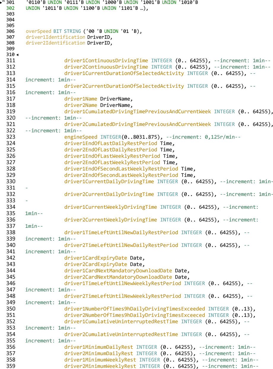
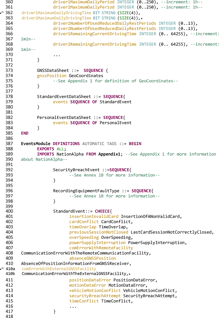


Appendix 14
REMOTE COMMUNICATION FUNCTIONU.K.
1.INTRODUCTIONU.K.
This Appendix specifies the design and the procedures to follow in order to perform the remote communication function (the Communication) as required in Article 9 of Regulation (EU) No 165/2014 (the Regulation).
DSC_1Regulation (EU) No 165/2014 determines that the tachograph shall be equipped with a remote communication functionality that shall enable agents of the competent control authorities to read tachograph information from passing vehicles by using remote interrogation equipment (the Remote early detection communication reader [REDCR]), specifically, interrogation equipment connecting wirelessly using CEN 5.8 GHz Dedicated Short Range Communication (DSRC) interfaces.U.K.
It is important to comprehend that this functionality is intended to serve only as a pre-filter in order to select vehicles for closer inspection, and it does not replace the formal inspection process as determined in the provisions of Regulation (EU) No 165/2014. See recital 9 in the preamble of this regulation, stating that remote communication between the tachograph and control authorities for roadside control purposes facilitates targeted roadside checks.
DSC_2The Data shall be exchanged using the Communication which shall be a wireless intercourse using 5.8 GHz DSRC wireless communications consistent with this Appendix and tested against the appropriate parameters of EN 300 674-1, {Electromagnetic compatibility and Radio spectrum Matters (ERM); Road Transport and Traffic Telematics (RTTT); Dedicated Short Range Communication (DSRC) transmission equipment (500 kbit/s / 250 kbit/s) operating in the 5,8 GHz Industrial, Scientific and Medical (ISM) band; Part 1: General characteristics and test methods for Road Side Units (RSU) and On -Board Units (OBU)}.U.K.
DSC_3The Communication shall be established with the communications equipment only when so requested by the equipment of the competent control authority using compliant radio-communication means (the Remote early detection communication reader (REDCR)).U.K.
DSC_4The Data shall be secured to ensure integrity.U.K.
DSC_5Access to the Data communicated shall be restricted to competent control authorities authorised to check infringements of Regulation (EC) No 561/2006 and of Regulation (EU) No 165/2014 and to workshops in so far as it is necessary to verify the correct functioning of the tachograph.U.K.
DSC_6The Data exchanged during the Communication shall be limited to the data necessary for the purpose of targeting roadside checks of vehicles with a potentially manipulated or misused tachograph.U.K.
DSC_7Data integrity and security shall be obtained by securing the Data within the Vehicle Unit (VU) and by passing only the secured payload data and security related data (see 5.4.4) across the wireless 5.8 GHz DSRC remote communication medium, meaning that only authorised persons of competent control authorities have the means to understand the data passed across the Communication and to verify its authenticity. See Appendix 11 Common Security Mechanisms.U.K.
DSC_8The Data shall contain a timestamp for the time of its last update.U.K.
DSC_9The content of the security data shall be known only to and within the control of the competent control authorities, and those parties with whom they share this information and is outwith the provisions of the Communication that is the subject of this Appendix, save that the Communication makes provision to transfer a packet of security data with every packet of payload data.U.K.
DSC_10The same architecture and equipment shall be capable be used to acquire other data concepts (such as weigh–on-board) using the architecture specified herein.U.K.
DSC_11For clarification, in accordance with the provisions of Regulation (EU) No 165/2014 (Article 7), data concerning the identity of the driver shall not be communicated across the Communication.U.K.
2.SCOPEU.K.
The scope of this Appendix is to specify how agents of the competent control authorities use a specified 5.8 GHz DSRC wireless communication to remotely obtain data (the Data) from a targeted vehicle that identifies that the targeted vehicle is in potential violation of Regulation (EU) No 165/2014 and should be targeted for consideration to be stopped for further investigation.
Regulation (EU) No 165/2014 requires that the Data collected shall be limited to data or pertaining to data that identifies a potential infringement, as defined in Article 9 of Regulation (EU) No 165/2014.
[F2In this scenario, the time available for communication is limited, because the Communication is targeted and of a short- range design. Further, the same communication means for remote tachograph monitoring (RTM) may also be used by the competent control authorities for other applications (such as the maximal weights and dimensions for heavy goods vehicles defined in Directive (EU) 2015/719) and such operations may be separate or sequential at the discretion of the competent control authorities.]
This Appendix specifies:
The communications equipment, procedures and protocols to be used for the Communication
The Standards and Regulations to which the radio equipment shall comply
The presentation of the Data to the Communication equipment
The enquiry and download procedures and sequence of operations
The Data to be transferred
Potential interpretation of the Data transferred across the Communication
The provisions for security data relating to the Communication
The availability of the Data to the competent control authorities
How the Remote early detection communication reader can request different freight and fleet data concepts
For clarification, this Appendix does not specify:
the collection of the Data operation and management within the VU (which shall be a function of product design unless specified elsewhere within Regulation (EU) No 165/2014)
the form of presentation of collected data to the agent of the competent control authorities, nor the criteria which shall be used by the competent control authorities to decide which vehicles to stop (which shall be a function of product design unless specified elsewhere within Regulation (EU) No 165/2014 or a policy decision of the competent control authorities). For clarification: the Communication only makes the Data available to the competent control authorities in order that they may make informed decisions
Data security provisions (such as encryption) concerning the content of the Data (which shall be specified within Appendix 11 Common Security Mechanisms).
detail of any data concepts other than RTM which may be obtained using the same architecture and equipment
detail of the behaviour and management between VU's and the DSRC-VU, nor the behaviour within the DSRC-VU (other than to provide the Data when so requested by an REDCR).
3.ACRONYMS, DEFINITIONS AND NOTATIONSU.K.
The following acronyms and definitions specific to this Appendix are used in this appendix:
the Antenna
electrical device which converts electric power into radio waves, and vice versa used in combination with a radio transmitter or radio receiver. In operation, a radio transmitter supplies an electric current oscillating at radio frequency to the antenna's terminals, and the antenna radiates the energy from the current as electromagnetic waves (radio waves). In reception, an antenna intercepts some of the power of an electromagnetic wave in order to produce a tiny voltage at its terminals, that is applied to a receiver to be amplified
the Communication
exchange of information/data between a DSRC-REDCR and a DSRC-VU according to section 5 in a master-slave relationship to obtain the Data.
the Data
secured data of defined format (see 5.4.4) requested by the DSRC-REDCR and provided to the DSRC-REDCR by the DSRC-VU across a 5.8 GHz DSRC link as defined in 5 below
Regulation (EC) No 165/2014
Regulation (EU) No 165/2014 of the European Parliament and of the Council of 4 February 2014 on tachographs in road transport, repealing Council Regulation (EEC) No 3821/85 on recording equipment in road transport and amending Regulation (EC) No 561/2006 of the European Parliament and of the Council on the harmonisation of certain social legislation relating to road transport
AID
Application Identifier
BLE
Bluetooth Low Energy
BST
Beacon Service Table
CIWD
Card insertion while driving
CRC
cyclic redundancy check
DSC (n)
identifier of a requirement for a specific DSRC appendix
DSRC
Dedicated Short Range Communication
DSRC-REDCR
DSRC — Remote Early Detection Communication Reader.
DSRC-VU
DSRC — Vehicle Unit. This is the ‘remote early detection facility’ defined in Annex 1C.
DWVC
Driving without valid card
EID
Element Identifier
LLC
Logical Link Control
LPDU
LLC Protocol Data Unit
OWS
Onboard Weighing System
PDU
Protocol Data Unit
REDCR
Remote early detection communication reader. This is the ‘remote early detection communication reader equipment’ defined in Annex 1C.
RTM
Remote Tachograph Monitoring
SM-REDCR
Security Module-Remote early detection communication reader
TARV
Telematics Applications for Regulated Vehicles (ISO 15638 series of Standards)
VU
Vehicle Unit
VUPM
Vehicle Unit Payload Memory
VUSM
Vehicle Unit Security Module
VST
Vehicle Service Table
WIM
Weigh in motion
WOB
Weigh on board
The specification defined in this Appendix refers to and depends upon all or parts of the following regulations and standards. Within the clauses of this Appendix the relevant standards, or relevant clauses of standards, are specified. In the event of any contradiction the clauses of this Appendix shall take precedence. In the event of any contradiction where no specification is clearly determined in this Appendix, operating within ERC 70-03 (and tested against the appropriate parameters of EN 300 674-1) shall take precedence, followed in descending order of preference by EN 12795, EN 12253 EN 12834 and EN 13372, 6.2, 6.3, 6.4 and 7.1.
Regulations and standards referenced in this Appendix are:
[1]
Regulation (EU) No 165/2014 of the European Parliament and of the Council of 4 February 2014 on tachographs in road transport, repealing Council Regulation (EEC) No 3821/85 on recording equipment in road transport and amending Regulation (EC) No 561/2006 of the European Parliament and of the Council on the harmonisation of certain social legislation relating to road transport.
[2]
Regulation (EC) No 561/2006 of the European Parliament and of the Council of 15 March 2006 on the harmonisation of certain social legislation relating to road transport and amending Council Regulations (EEC) No 3821/85 and (EC) No 2135/98 and repealing Council Regulation (EEC) No 3820/85 (Text with EEA relevance).
[3]
ERC 70-03 CEPT: ECC Recommendation 70-03: Relating to the Use of Short Range Devices (SRD)
[4]
ISO 15638 Intelligent transport systems — Framework for cooperative telematics applications for regulated commercial freight vehicles (TARV).
[5]
EN 300 674-1 Electromagnetic compatibility and Radio spectrum Matters (ERM); Road Transport and Traffic Telematics (RTTT); Dedicated Short Range Communication (DSRC) transmission equipment (500 kbit/s / 250 kbit/s) operating in the 5,8 GHz Industrial, Scientific and Medical (ISM) band; Part 1: General characteristics and test methods for Road Side Units (RSU) and On-Board Units (OBU).
[6]
EN 12253 Road transport and traffic telematics — Dedicated short-range communication — Physical layer using microwave at 5.8 GHz.
[7]
EN 12795 Road transport and traffic telematics — Dedicated short-range communication — Data link layer: medium access and logical link control.
[8]
EN 12834 Road transport and traffic telematics — Dedicated short-range communication — Application layer.
[9]
EN 13372 Road transport and traffic telematics — Dedicated short-range communication — Profiles for RTTT applications
[10]
ISO 14906 Electronic fee collection — Application interface definition for dedicated short- range communication
4.OPERATIONAL SCENARIOSU.K.
4.1OverviewU.K.
Regulation (EU) No 165/2014 provides specific and controlled scenarios within which the Communication is to be used.
The scenarios supported are:
‘Communication Profile 1: Roadside inspection using a short range wireless communication Remote Early Detection Communication Reader instigating a physical roadside inspection (master-:-slave)
Reader Profile 1a: via a hand aimed or temporary roadside mounted and aimed Remote Early Detection Communication
Reader Profile 1b: via a vehicle mounted and directed Remote Early Detection Communication Reader’.
4.1.1Preconditions to data transfer via 5,8 GHz DSRC interfaceU.K.
NOTE: In order to understand the context of the preconditions the reader is referred to Figure 14.3 below.U.K.
4.1.1.1Data held in VUU.K.
DSC_12The VU shall be responsible to keep updated every 60 seconds and maintain the data to be stored in the VU, without any involvement of the DSRC communication function. The means by which this is achieved is internal to the VU, specified in Regulation (EU) No 165/2014, Annex 1 C, section 3.19 ‘Remote communication for targeted roadside checks’ and is not specified in this Appendix.U.K.
4.1.1.2Data provided to DSRC-VU FacilityU.K.
DSC_13The VU shall be responsible to update the DSRC tachograph data (the Data) whenever the data stored in the VU is updated at the interval determined in 4.1.1.1 (DSC_12), without any involvement of the DSRC communication function.U.K.
DSC_14The VU data shall be used as a basis to populate and update the Data, the means by which this is achieved, is specified in Annex 1.C, section 3.19 ‘Remote communication for targeted roadside checks’ or if there is no such specification it is a function of product design and is not specified in this Appendix. For the design of the connection between DSRC-VU facility and the VU, please refer to section 5.6.U.K.
4.1.1.3Content of the DataU.K.
DSC_15The content and format of the Data shall be such that, once decrypted, it shall be structured and made available in the form and format specified in 5.4.4 of this Appendix (Data structures).U.K.
4.1.1.4Data presentationU.K.
DSC_16The Data, having been kept frequently updated in accordance with the procedures determined in 4.1.1.1, shall be secured prior to presentation to the DSRC-VU, and presented as a secured data concept value, for temporary storage in the DSRC-VU as the current version of the Data. This data is transferred from the VUSM to the DSRC function VUPM. The VUSM and VUPM are functions and not necessarily physical entities. The form of physical instantiation to perform these functions shall be a matter of product design unless specified elsewhere in Regulation (EU) No 165/2014.U.K.
4.1.1.5Security dataU.K.
DSC_17Security data (securityData), comprising the data required by the REDCR to complete its ability to decrypt the Data shall be supplied as defined in Appendix 11 Common Security Mechanisms and presented as a data concept value, for temporary storage in the DSRC-VU as the current version of securityData, in the form defined in this Appendix section 5.4.4.U.K.
4.1.1.6VUPM data available for transfer across the DSRC interfaceU.K.
DSC_18The data concept which shall always be available in the DSRC function VUPM for immediate transfer upon request by the REDCR is defined in section 5.4.4 for full ASN.1 Module specifications.U.K.
General overview of communication Profile 1U.K.
This profile covers the use case where an agent of the competent control authorities, uses a short range remote communication Remote Early Detection Communication Reader (5.8 GHz DSRC interfaces operating within ERC 70-03, and tested against the appropriate parameters of EN 300 674-1 as described in section 5) (the REDCR) to remotely identify a vehicle which is potentially in violation of Regulation (EU) No 165/2014. Once identified, the agent of the competent control authorities who is controlling the interrogation decides whether the vehicle should be stopped.
4.1.2Profile 1a: via a hand aimed or temporary roadside mounted and aimed Remote Early Detection Communication ReaderU.K.
In this use case the agent of the competent control authorities is situated at the roadside, and aims a hand held, tripod mounted, or similar portable, REDCR from the roadside towards the centre of the windshield of the targeted vehicle. The interrogation is made using 5.8 GHz DSRC interfaces operating within ERC 70-03, and tested against the appropriate parameters of EN 300 674-1 as described in section 5. See Figure 14.1 (Use Case 1).

4.1.3Profile 1b: via a vehicle mounted and directed Remote Early Detection Communication Reader (REDCR)U.K.
In this use case the agent of the competent control authorities is situated within a moving vehicle, and either aims a hand held, portable REDCR from the vehicle towards the centre of the windshield of the targeted vehicle, or the REDCR is mounted within or on the vehicle so as to point towards the centre of the windshield of the targeted vehicle when the Remote Early Detection Communication Reader's vehicle is in a particular position relevant to the targeted vehicle (for example directly ahead in a stream of traffic). The interrogation is made using 5.8 GHz DSRC interfaces operating within ERC 70-03, and tested against the appropriate parameters of EN 300 674-1 as described in section 5. See Figure 14.2. (Use Case 2).

4.2Security/IntegrityU.K.
To give the possibility to verify the authenticity and integrity of downloaded data through the remote communication, the secured Data is verified and decrypted in accordance with Appendix 11 Common Security Mechanisms.
5.REMOTE COMMUNICATION DESIGN AND PROTOCOLSU.K.
5.1DesignU.K.
The design of the remote communication function in the Smart Tachograph is shown as described in Figure 14.3.

DSC_19The following functions are located in the VU:U.K.
Security Module (VUSM). This function present in the VU is responsible for securing the Data which is to be transmitted from the DSRC-VU to the agent of the competent control authorities via remote communication.
The secured data is stored in the VUSM memory. At intervals determined in 4.1.1.1 (DSC_12), the VU encrypts and replenishes the RTMdata concept (which comprises payload data and security data concept values determined below in this Appendix) held in the memory of the DSRC-VU. The operation of the security module is defined in Appendix 11 Common Security Mechanisms and outwith the scope of this Appendix, save that it shall be required to provide updates to the VU Communication facility each time the VUSM data changes.
The communication between the VU and the DSRC-VU may be a wired communication or a Bluetooth Low Energy (BLE) communication, and the physical location of the DSRC-VU may be integral with the antenna on the windshield of the vehicle, may be internal to the VU, or located somewhere between.
The DSRC-VU shall have a reliable source of power available at all times. The means by which it is provided with its power is a design decision.
The memory of the DSRC-VU shall be non-volatile in order to maintain the Data in the DSRC-VU even when the vehicle ignition is switched off.
If the communication between the VU and the DSRC-VU is made via BLE and the power source is a non-recharging battery, the power source of the DSRC-VU shall be replaced at every Periodic Inspection, and the manufacturer of the DSRC-VU equipment shall be responsible to ensure that the power supply is adequate to last from one Periodic Inspection to the next Periodic Inspection, maintaining normal access to the data by an REDCR throughout the period without failure or interruption.
VU RTM ‘payload memory’ facility (VUPM). This function present in the VU is responsible for providing and updating the Data. The content of The Data. (‘TachographPayload’) is defined in 5.4.4/5.4.5 below and is updated at the interval determined in 4.1.1.1 (DSC_12).
DSRC-VU. This is the function, within or connected to the antenna and in communication with the VU through a wired or wireless (BLE) connection, which holds the current data (VUPM-data) and manages the response to an interrogation across the 5.8 GHz DSRC medium. Disconnection of the DSRC facility or interference during normal vehicle operation with the functioning of the DSRC facility shall be construed as a violation of Regulation (EU) No 165/2014.
Security module (REDCR) (SM-REDCR) is the function used to decrypt and check integrity of the data originating from the VU. The means by which this is achieved is determined in Appendix 11 Common Security Mechanisms, and is not defined in this Appendix.
The DSRC facility (REDCR) (DSRC-REDCR) function comprises a 5.8 GHz transceiver and associated firmware and software which manages the Communication with the DSRC-VU according to this Appendix.
The DSRC-REDCR interrogates the DSRC-VU of the targeted vehicle and obtains the Data (the targeted vehicle's current VUPM-data) via the DSRC link and processes and stores the received data in its SM-REDCR.
[F2The DSRC-VU antenna shall be positioned at a location where it optimizes the DSRC communication between the vehicle and the roadside reader antenna, when the reader is installed 15 meters distance in front of the vehicle and 2 meters height, targeting the horizontal and vertical centre of the windscreen. For light vehicles an installation corresponding to the upper part of the windscreen is suitable. For all the other vehicles the DSRC antenna shall be installed either near the lower or near the upper part of the windscreen.]
DSC_20The Antenna and The Communication shall operate within ERC 70-03, tested against the appropriate parameters of EN 300 674-1 as described in section 5. The Antenna and the Communication can implement mitigation techniques against the risk of wireless interference as described in ECC report 228 using e.g., filters in the CEN DSRC 5.8 GHz communication.U.K.
DSC_21The DSRC antenna shall be connected to the DSRC-VU facility either directly within the module mounted to or close to the windshield, or through a dedicated cable constructed in a manner to make illegal disconnection difficult. Disconnection of or interference with the functioning of Antenna shall be a violation of Regulation (EU) No 165/2014. Deliberate masking or otherwise detrimentally affecting the operational performance of the Antenna shall be construed as a violation of Regulation (EU) No 165/2014.U.K.
DSC_22[F2The form factor of the antenna is not defined and shall be a commercial decision, so long as the fitted DSRC-VU meets the conformance requirements defined in section 5 below. The antenna shall be positioned as determined in DSC_19 and efficiently support the use cases described in in 4.1.2 and 4.1.3.]U.K.
Figure 14.4
Example of positioning of the 5,8 GHz DSRC antenna in the windshield of regulated vehicles

The form factor of the REDCR and its antenna may vary according to the circumstances of the reader (tripod mounted, hand held, vehicle mounted, etc.) and the modus operandi employed by the agent of the competent control authorities.
A display and/or notification function is used to present the results of the remote communication function to the agent of the competent control authorities. A display may be provided on a screen, as a printed output, an audio signal, or a combination of such notifications. The form of such display and/or notification is a matter of the requirements of the agents of the competent control authorities and equipment design and is not specified within this Appendix.
DSC_23The design and form factor of the REDCR shall be a function of commercial design, operating within ERC 70-03, and the design and performance specifications defined in this Appendix, (section 5.3.2), thus providing the marketplace maximum flexibility to design and provide equipment to cover the specific interrogation scenarios of any particular competent control authority.U.K.
DSC_24The design and form factor of the DSRC-VU and its positioning inside or outside the VU shall be a function of commercial design, operating within ERC 70-03 and the design and performance specifications defined in this Appendix (section 5.3.2) and within this Clause (5.1).U.K.
DSC_25However, the DSRC-VU shall be reasonably capable to accept data concept values from other intelligent vehicle equipment by means of an open industry standard connection and protocols. (For example from weigh on board equipment), so long as such data concepts are identified by unique and known application identifiers/file names, and the instructions to operate such protocols shall be made available to the European Commission, and available without charge to manufacturers of relevant equipment.U.K.
5.2WorkflowU.K.
5.2.1OperationsU.K.
The workflow of operations is represented in Figure 14.5.

The steps are described below:
a.
Whenever the vehicle is in operation (ignition ON) the tachograph is providing data to the VU function. The VU function prepares the Data for the remote communication function (encrypted) and updates the VUPM held in the memory of the DSRC-VU (as defined in 4.1.1.1 — 4.1.1.2). The Data collected shall be formatted as determined in 5.4.4 — 5.4.5 below.
b.
On every occasion that the Data is updated, the timestamp defined in the security data concept shall be updated.
c.
The VUSM function secures the data in accordance with the procedures determined in Appendix 11.
d.
On every occasion that the Data is updated (see 4.1.1.1 — 4.1.1.2), the Data shall be transferred to the DSRC-VU, where it replaces any previous data, in order that updated current data (the Data) shall always be available to be provided in the event of an interrogation by an REDCR. When supplied by the VU to the DSRC-VU the Data shall be identifiable by the filename RTMData or by ApplicationID and Attribute identifiers.
e.
If an agent of the competent control authorities wishes to target a vehicle and collect the Data from the targeted vehicle, the agent of the competent control authorities shall first insert his/her smartcard in the REDCR to enable the Communication and to allow the SM-REDCR to verify its authenticity and decrypt the data.
f.
The agent of the competent control authority then targets a vehicle and requests the data through remote communication. The REDCR opens a 5.8 GHz DSRC interface session with the DSRC-VU of the targeted vehicle, and requests the Data. The Data is transferred to the REDCR through the wireless communication system as a DSRC Attribute using the Application service GET as defined in 5.4. The Attribute contains the encrypted payload data values and the DSRC security data.
g.
The data is analyzed by the REDCR equipment and provided to the agent of the competent control authority.
h.
The agent of the competent control authority uses the data to assist in a decision of whether or not to stop for a detailed inspection, or ask another agent of the competent control authority to stop the vehicle.
5.2.2Interpretation of the Data received via the DSRC communicationU.K.
DSC_26Data received across the 5.8 GHz interface shall carry the meaning and import defined in 5.4.4 and 5.4.5 below and only that meaning and import, and shall be understood within the objectives defined therein. In accordance with the provisions of Regulation (EU) No 165/2014, the Data shall be used only to provide relevant information to a competent control authority to assist them to determine which vehicle should be stopped for physical inspection, and shall be subsequently destroyed in accordance with Article 9 of Regulation (EU) No 165/2014.U.K.
5.3DSRC Physical interface parameters for remote communicationU.K.
5.3.1Location constraintsU.K.
DSC_27The remote interrogation of vehicles using a 5.8GHz DSRC interface should not be used within 200 metres of an operational 5.8 GHz DSRC gantry.U.K.
5.3.2Downlink and uplink parametersU.K.
DSC_28The equipment used for remote tachograph monitoring shall conform to and operate within ERC70-03 and the parameters defined in Tables 14.1 and 14.2 below.U.K.
DSC_29Further, to ensure compatibility with the operational parameters of other standardised 5.8 GHz DSRC systems, the equipment used for remote tachograph monitoring shall conform to parameters from EN 12253 and EN 13372.U.K.
Namely:
Table 14.1
Downlink parameters
a – Downlink parameters subject to conformance testing in accordance with relevant parameter test from EN 300 674-1. | |||
| Item No | Parameter | Value(s) | Remark |
|---|---|---|---|
| D1 | Downlink Carrier Frequencies | There are four alternatives which may be used by an REDCR:
| Within ERC 70-03. Carrier Frequencies may be selected by the implementer of the roadside system and need not be known in the DSRC-VU (Consistent with EN 12253, EN 13372) |
| D1aa | Tolerance of Carrier Frequencies | within ± 5 ppm | (Consistent with EN 12253) |
| D2a | RSU (REDCR) Transmitter Spectrum Mask | Within ERC 70-03. REDCR shall be according to Class B,C as defined in EN 12253. No other specific requirement within this Annex | Parameter used for controlling interference between interrogators in proximity (as defined in EN 12253 and EN 13372). |
| D3 | OBU(DSRC-VU) Minimum Frequency Range | 5,795 — 5,815 GHz | (Consistent with EN 12253) |
| D4a | Maximum E.I.R.P. | Within ERC 70-03 (unlicensed) and within National Regulation Maximum + 33 dBm | (Consistent with EN 12253) |
| D4a | Angular E.I.R.P. mask | According to declared and published specification of interrogator designer | (Consistent with EN 12253) |
| D5 | Polarisation | Left hand circular | (Consistent with EN 12253) |
| D5a | Cross-Polarisation | XPD: In bore sight: (REDCR) RSU t ≥ 15 dB (DSRC-VU) OBU r ≥ 10 dB At -3 dB area: (REDCR) RSU t ≥ 10 dB (DSRC-VU) OBU r ≥ 6 dB | (Consistent with EN 12253) |
| D6a | Modulation | Two level amplitude modulation. | (Consistent with EN 12253) |
| D6aa | Modulation Index | 0,5 ... 0,9 | (Consistent with EN 12253) |
| D6b | Eye Pattern | ≥ 90 % (time) / ≥ 85 % (amplitude) | |
| D7a | Data Coding | FM0 ‘1’ bit has transitions only at the beginning and end of the bit interval. ‘0’ bit has an additional transition in the middle of the bit interval compared to the ‘1’ bit. | (Consistent with EN 12253) |
| D8a | Bit rate | 500 kBit/s | (Consistent with EN 12253) |
| D8a | Tolerance of Bit Clock | better than ± 100 ppm | (Consistent with EN 12253) |
| D9a | Bit Error Rate (B.E.R.) for communication | ≤ 10– 6 when incident power at OBU (DSRC-VU) is in the range given by [D11a to D11b]. | (Consistent with EN 12253) |
| D10 | Wake-up trigger for OBU (DSRC-VU) | OBU (DSRC-VU) shall wake up on receiving any frame with 11 or more octets (including preamble) | No special wake-up pattern is necessary. DSRC-VU may wake up on receiving a frame with less than 11 octets (Consistent with EN 12253) |
| D10a | Maximum Start Time | ≤ 5 ms | (Consistent with EN 12253) |
| D11 | Communication zone | Spatial region within which a B.E.R. according to D9a is achieved | (Consistent with EN 12253) |
| D11aa | Power Limit for communication (upper). | – 24dBm | (Consistent with EN 12253) |
| D11ba | Power Limit for communication (lower). | Incident power:
| (Consistent with EN 12253) Extended requirement for horizontal angles up to ±45°, due to the use cases defined in this annex. |
| D12a | Cut-off power level of (DSRC-VU) | – 60 dBm | (Consistent with EN 12253) |
| D13 | Preamble | Preamble is mandatory. | (Consistent with EN 12253) |
| D13a | Preamble Length and Pattern | 16 bits ± 1 bit of FM0 coded ‘1’ bits | (Consistent with EN 12253) |
| D13b | Preamble Wave form | An alternating sequence of low level and high level with pulse duration of 2 μs. The tolerance is given byD8a | (Consistent with EN 12253) |
| D13c | Trailing Bits | The RSU (REDCR) is permitted to transmit a maximum of 8 bits after the end flag. An OBU (DSRC-VU) is not required to take these additional bits into account. | (Consistent with EN 12253) |
Table 14.2
Uplink parameters
a – Uplink parameters subject to conformance testing in accordance with relevant parameter test from EN 300 674-1 | |||
| Item No. | Parameter | Value(s) | Remark |
|---|---|---|---|
| U1a | Sub-carrier Frequencies | A OBU (DSRC-VU) shall support 1,5 MHz and 2,0 MHz An RSU (REDCR) shall support 1,5 MHz or 2,0 MHz or both. U1-0: 1,5 MHz U1-1: 2,0 MHz | Selection of sub-carrier frequency (1,5 MHz or 2,0 MHz) depends on the EN 13372 profile selected. |
| U1aa | Tolerance of Sub- carrier Frequencies | within ± 0,1 % | (Consistent with EN 12253) |
| U1b | Use of Side Bands | Same data on both sides | (Consistent with EN 12253) |
| U2a | OBU (DSRC-VU) Transmitter Spectrum Mask | According to EN12253 1) Out band power: see ETSI EN 300674-1 2) In band power: [U4a] dBm in 500 kHz 3) Emission in any other uplink channel: U2(3)-1 = – 35 dBm in 500 kHz | (Consistent with EN 12253) |
| U4aa | Maximum Single Side Band E.I.R.P. (boresight) | Two options:
| According to declared and published specification of equipment designer |
| U4ba | Maximum Single Side Band E.I.R.P. (35°) | Two options:
| According to declared and published specification of equipment designer |
| U5 | Polarisation | Left hand circular | (Consistent with EN 12253) |
| U5a | Cross Polarisation | XPD: In bore sight: (REDCR) RSU r ≥ 15 dB (DSRC-VU) OBU t ≥ 10 dB At – 3 dB: (REDCR) RSU r ≥ 10 dB (DSRC-VU) OBU t ≥ 6 dB | (Consistent with EN 12253) |
| U6 | Sub-Carrier Modulation | 2-PSK Encoded data synchronised with sub-carrier: Transitions of encoded data coincide with transitions of sub- carrier. | (Consistent with EN 12253) |
| U6b | Duty Cycle | Duty Cycle: 50 % ± α, α ≤ 5 % | (Consistent with EN 12253) |
| U6c | Modulation on Carrier | Multiplication of modulated sub- carrier with carrier. | (Consistent with EN 12253) |
| U7a | Data Coding | NRZI (No transition at beginning of ‘1’ bit, transition at beginning of ‘0’ bit, no transition within bit) | (Consistent with EN 12253) |
| U8a | Bit Rate | 250 kbit/s | (Consistent with EN 12253) |
| U8a | Tolerance of Bit Clock | Within ± 1 000 ppm | (Consistent with EN 12253) |
| U9 | Bit Error Rate (B.E.R.) for communication | ≤10– 6 | (Consistent with EN 12253) |
| U11 | Communication Zone | The spatial region within which the DSRC-VU is situated such that its transmissions are received by the REDCR with a B.E.R. of less than that given by U9a. | (Consistent with EN 12253) |
| U12aa | Conversion Gain (lower limit) | 1 dB for each side band Range of angle: Circularly symmetric between bore sight and ± 35° and | |
| within – 45° ± 45° Corresponding to the plane parallel to the road surface when the DSRC-VU later is installed in the vehicle (Azimuth) | Greater that the specified value range for horizontal angles up to ± 45°, due to the use cases defined in this annex. | ||
| U12ba | Conversion Gain (upper limit) | 10 dB for each side band | Less than the specified value range for each side band within a circular cone around boresight of ± 45° opening angle |
| U13 | Preamble | Preamble is mandatory. | (Consistent with EN 12253) |
| U13a | Preamble Length and Pattern | 32 to 36 μs modulated with sub- carrier only, then 8 bits of NRZI coded ‘0’ bits. | (Consistent with EN 12253) |
| U13b | Trailing Bits | The DSRC-VU is permitted to transmit a maximum of 8 bits after the end flag. A RSU (REDCR) is not required to take these additional bits into account. | (Consistent with EN 12253) |
5.3.3Antenna designU.K.
5.3.3.1REDCR antennaU.K.
DSC_30The design of the REDCR antenna shall be a function of commercial design, operating within the limits defined in 5.3.2 which is adapted to optimise the reading performance of the DSRC-REDCR for the specific purpose and read circumstances in which the REDCR has been designed to operate.U.K.
5.3.3.2VU antennaU.K.
DSC_31The design of the DSRC-VU antenna shall be a function of commercial design, operating within the limits defined in 5.3.2 which is adapted to optimise the reading performance of the DSRC-REDCR for the specific purpose and read circumstances in which the REDCR has been designed to operate.U.K.
DSC_32The VU antenna shall be fixed to, or close to, the front windshield of the vehicle as specified in 5.1 above.U.K.
DSC_33In the test environment in a workshop (see section 6.3), a DSRC-VU antenna, affixed according to 5.1 above, shall successfully connect with a standard test communication and successfully provide an RTM transaction as defined within this Appendix, at a distance between 2 and 10 meters, better than 99 % of the time, averaged over 1 000 read interrogations.U.K.
5.4DSRC Protocol requirements for RTMU.K.
5.4.1OverviewU.K.
DSC_34The transaction protocol to download the Data across the 5.8 GHz DSRC interface link shall be according to the following steps. This section describes a transaction flow under ideal conditions without retransmissions or communication interrupts.U.K.
NOTE The purpose of the initialisation phase (Step 1) is to set up the communication between the REDCR and DSRC-VUs that have entered the 5.8 GHz DSRC (master-slave) transaction zone but have not yet established communication with the REDCR, and to notify the application processes.U.K.
— Step 1
Initialisation. The REDCR sends a frame containing a ‘beacon service table’ (BST) that includes the application identifiers (AIDs) in the service list that it supports. In the RTM application this will simply be the service with the AID value = 2 (Freight&Fleet). The DSRC-VU evaluates the received BST, and shall respond (see below) with the list of the supported applications within the Freight&Fleet domain, or shall not respond if none are supported. If the REDCR does not offer AID=2, the DSRC-VU shall not answer to the REDCR.
— Step 2
The DSRC-VU sends a frame containing a request for a private window allocation.
— Step 3
The REDCR sends a frame containing a private window allocation.
— Step 4
The DSRC-VU uses the allocated private window to send a frame containing its vehicle service table (VST). This VST includes a list of all the different application instantiations that this DSRC-VU supports in the framework of AID=2. The different instantiations shall be identified by means of uniquely generated EIDs, each associated with an Application Context Mark parameter value indicating the application and standard supported.
— Step 5
Next the REDCR analyses the offered VST, and either terminates the connection (RELEASE) since it is not interested in anything the VST has to offer (i.e. it is receiving a VST from a DSRC-VU that is not supporting the RTM transaction), or, if it receives an appropriate VST it starts an app instantiation.
— Step 6
To bring this about, the REDCR shall send a frame containing a command to retrieve the RTM data, identifying the RTM application instantiation by specifying the identifier corresponding to the RTM application instantiation (as specified by the DSRC-VU in the VST), and shall allocate a private window.
— Step 7
The DSRC-VU uses the newly allocated private window to send a frame that contains the addressed identifier corresponding to the RTM application instantiation as provided in the VST, followed by the attribute RtmData (payload element + security element).
— Step 8
If there are multiple services requested, the value ‘n’ is changed to the next service reference number and the process repeated.
— Step 9
The REDCR confirms receipt of the data by sending a frame containing a RELEASE command to the DSRC-VU to terminate the session OR if it has failed to validate a successful receipt of the LDPU goes back to step 6.
See Figure 14.6 for a pictorial description of the transaction protocol.

5.4.2CommandsU.K.
DSC_35The following commands are the only functions used in an RTM transaction phaseU.K.
— INITIALISATION.request
:
A command, issued from the REDCR in the form of a broadcast with definition of applications that the REDCR supports.
— INITIALISATION.response
:
An answer from the DSRC-VU confirming the connection and containing a list of supported application instances with characteristics and information how to address them (EID).
— GET.request
:
A command, issued from the REDCR to the DSRC-VU, that specifies the application instantiation to be addressed by means of a defined EID, as received in the VST, instructing the DSRC-VU to send the selected attribute(s) with the Data. The objective of the GET command is for the REDCR to obtain the Data from the DSRC-VU.
— GET.response
:
An answer from the DSRC-VU that contains the Data requested.
— ACTION.request ECHO
:
A command, instructing the DSRC-VU to send back data from the DSRC-VU to the REDCR. The objective of the ECHO command is to enable workshops or type approval test facilities to test that the DSRC link is working without needing access to security credentials.
— ACTION.response ECHO
:
An answer from the DSRC VU on the ECHO command.
— EVENT_REPORT.request RELEASE
:
A command, instructing the DSRC-VU that the transaction is ended. The objective of the RELEASE command is to end the session with the DSRC-VU. On receipt of the RELEASE the DSRC-VU shall not respond to any further interrogations under the current connection. Note that according to EN 12834 a DSRC-VU will not connect twice to the same interrogator unless it has been out of the communication zone for 255 seconds or if the Beacon ID of the interrogator is changed.
5.4.3Interrogation command sequenceU.K.
DSC_36From the perspective of the command and response sequence, the transaction is described as follows:U.K.
| Sequence | Sender | Receiver | Description | Action | |
|---|---|---|---|---|---|
| 1 | REDCR | > | DSRC-VU | Initialisation of the communication link — Request | REDCR broadcasts BST |
| 2 | DSRC-VU | > | REDCR | Initialisation of the communication link — Response | If BST supports AID=2 then DSRC-VU Requests a private window |
| 3 | REDCR | > | DSRC-VU | Grants a private window | Sends Frame containing private window allocation |
| 4 | DSRC-VU | > | REDCR | Sends VST | Sends Frame comprising VST |
| 5 | REDCR | > | DSRC-VU | Sends GET.request for data in Attribute for specific EID | |
| 6 | DSRC-VU | > | REDCR | Sends GET.response with requested Attribute for specific EID | Sends Attribute (RTMData, OWSData….) with data for specific EID |
| [F27 | REDCR | > | DSRC-VU | Sends GET.request for data of other Attribute (if appropriate) ] | |
| 8 | DSRC-VU | > | REDCR | Sends GET.response with requested Attribute | Sends Attribute with data for specific EID |
| 9 | REDCR | > | DSRC-VU | Acknowledges successful receipt of data | Sends RELEASE command which closes transaction |
| 10 | DSRC-VU | Closes transaction |
An example of the transaction sequence and contents of the exchanged frames is defined in clauses 5.4.7 and 5.4.8
5.4.4Data structuresU.K.
DSC_37The semantic structure of the Data when passed across the 5.8 GHz DSRC interface shall be consistent with what described in this Appendix. The way these data are structured is specified in this clause.U.K.
DSC_38The payload (RTM data) consists of the concatenation ofU.K.
1.
EncryptedTachographPayload data, which is the encryption of the TachographPayload defined in ASN.1 in section 5.4.5. The method of encryption is described in Appendix 11
2.
DSRCSecurityData, specified in Appendix 11.
DSC_39The RTM Data is being addressed as RTM Attribute=1 and is transferred in the RTM container = 10.U.K.
DSC_40The RTM Context Mark shall identify the supported standard part in the TARV series of standards (RTM corresponds to Part 9)U.K.
The ASN.1 module definition for the DSRC data within the RTM application is defined as follows:


5.4.5Elements of RtmData, actions performed and definitionsU.K.
DSC_41The data values to be calculated by the VU and used to update the secured data in the DSRC-VU shall be calculated according to the rules defined in Table 14.3:U.K.
| Table 14.3 | |||
| Elements of RtmData, actions performed and definitions | |||
| (1) RTM Data Element | (2) Action performed by the VU | (3) ASN.1 definition of data | |
|---|---|---|---|
RTM1 Vehicle Registration Plate | The VU shall set the value of the tp15638VehicleRegistrationPlate data element RTM1 from the recorded value of the data type VehicleRegistrationIdentification as defined in Appendix 1 VehicleRegistrationIdentification | Vehicle Registration Plate expressed as a string of characters |  |
RTM2 Speeding Event | The VU shall generate a boolean value for data element RTM2 tp15638SpeedingEvent. The tp15638SpeedingEvent value shall be calculated by the VU from the number of Over Speeding Events recorded in the VU in the last 10 days of occurrence, as defined in Annex 1C. If there is at least one tp15638SpeedingEvent in the last 10 days of occurrence, the tp15638SpeedingEvent value shall be set to TRUE. ELSE if there are no events in the last 10 days of occurrence, the tp15638SpeedingEvent shall be set to FALSE. | 1 (TRUE) — Indicates irregularities in speed within last 10 days of occurrence |  |
RTM3 Driving Without Valid Card | The VU shall generate a boolean value for data element RTM3 tp15638DrivingWithoutValidCard. The VU shall assign a value of True to the tp15638DrivingWithoutValidCard variable if the VU data has recorded at least one event in the last 10 days of occurrence of type ‘Driving without an appropriate card’ event as defined in Annex 1C. ELSE if there are no events in the last 10 days of occurrence, the tp15638DrivingWithoutValidCard variable shall be set to FALSE. | 1 (TRUE) = Indicates invalid card usage |  |
RTM4 Valid Driver Card | The VU shall generate a boolean value for data element RTM4 tp15638DriverCard on the basis of the data stored in the VU and defined in Appendix 1. If no valid driver card is present the VU shall set the variable to TRUE ELSE if a valid driver card is present the VU shall set the variable to FALSE | 0 (FALSE) = Indicates a valid driver card |  |
RTM5 Card Insertion while Driving | The VU shall generate a boolean value for data element RTM5. The VU shall assign a value of TRUE to the tp15638CardInsertion variable if the VU data has recorded in the last 10 days of occurrence at least one event of type ‘Card insertion while driving.’ as defined in Annex 1C. ELSE if there are no such events in the last 10 days of occurrence, the tp15638CardInsertion variable shall be set to FALSE. | 1 (TRUE) = Indicates card insertion while driving within last 10 days of occurrence |  |
RTM6 Motion Data Error | The VU shall generate a boolean value for data element RTM6. The VU shall assign a value of TRUE to the tp15638MotionDataError variable if the VU data has in the last 10 days of occurrence recorded at least one event of type ‘Motion data error’ as defined in Annex 1C. ELSE if there are no such events in the last 10 days of occurrence, the tp15638MotionDataError variable shall be set to FALSE. | 1 (TRUE) = Indicates motion data error within last 10 days of occurrence |  |
RTM7 Vehicle Motion Conflict | The VU shall generate a boolean value for data element RTM7. The VU shall assign a value of TRUE to the tp15638vehicleMotionConflict variable if the VU data has in the last 10 days recorded at least one event of type Vehicle Motion Conflict (value ‘0A’H ). ELSE if there are no events in the last 10 days of occurrence, the tp15638vehicleMotionConflict variable shall be set to FALSE. | 1 (TRUE) = Indicates motion conflict within last 10 days of occurrence |  |
RTM8 2nd Driver Card | The VU shall generate a boolean value for data element RTM8 on the basis of Annex 1C (‘Driver Activity Data’ CREW and CO-DRIVER). If a 2nd valid driver card is present the VU shall set the variable to TRUE ELSE if a 2nd valid driver card is not present the VU shall set the variable to FALSE | 1 (TRUE) = Indicates a second driver card inserted |  |
RTM9 Current Activity | The VU shall generate a boolean value for data element RTM9. If the current activity is recorded in the VU as any activity other than ‘DRIVING’ as defined in Annex 1C the VU shall set the variable to TRUE ELSE if the current activity is recorded in the VU as ‘DRIVING’ the VU shall set the variable to FALSE | 1 (TRUE) = other activity selected; 0 (FALSE) = driving selected |  |
RTM10 Last Session Closed | The VU shall generate a boolean value for data element RTM10. If the last card session was not properly closed as defined in Annex 1C the VU shall set the variable to TRUE. ELSE if the last card session was properly closed the VU shall set the variable to FALSE | 1 (TRUE) = improperly closed 0 (FALSE) = properly closed |  |
RTM11 Power Supply Interruption | The VU shall generate an integer value for data element RTM11. The VU shall assign a value for the tp15638PowerSupplyInterruption variable equal to the longest power supply interruption according to Article 9, Reg (EU) 165/2014 of type ‘Power supply interruption’ as defined in Annex 1C. ELSE if in the last 10 days of occurrence there are have been no Power supply interruption events the value of the integer shall be set to 0. | — Number of power supply interruptions in last 10 days of occurrence |  |
[F2RTM12 Sensor Fault | The VU shall generate an integer value for data element RTM12. The VU shall assign to the variable sensorFault a value of:
| – sensor fault one octet as per data dictionary ] |  |
RTM13 Time Adjustment | The VU shall generate an integer value (timeReal from Appendix 1) for data element RTM13 on the basis of the presence of Time Adjustment data as defined in Annex 1C. The VU shall assign the value of time at which the last time adjustment data event has occurred. ELSE if no ‘Time Adjustment’ event. as defined in Annex 1C is present in the VU data it shall set a value of 0 | Time of the last time adjustment |  |
RTM14 Security Breach Attempt | The VU shall generate an integer value (timeReal from Appendix 1) for data element RTM14 on the basis of the presence of a Security breach attempt event as defined in Annex 1C. The VU shall set the value of the time of the latest security breach attempt event recorded by the VU. ELSE if no ‘security breach attempt’ event as defined in Annex 1C is present in the VU data it shall set a value of 0x00FF. | Time of last breach attempt — Default value =0x00FF |  |
RTM15 Last Calibration | The VU shall generate an integer value (timeReal from Appendix 1) for data element RTM15 on the basis of the presence of Last Calibration data as defined in Annex 1C. The VU shall set the value of time of the latest two calibrations (RTM15 and RTM16), which are set in VuCalibrationData defined in Appendix 1. The VU shall set the value for RTM15 to the timeReal of the latest calibration record. | Time of last calibration data |  |
RTM16 Previous Calibration | The VU shall generate an integer value (timeReal from Appendix 1) for data element RTM16 of the calibration record preceding that of the last calibration ELSE if there has been no previous calibration the VU shall set the value of RTM16 to 0. | Time of previous calibration data |  |
RTM17 Date Tachograph Connected | For data element RTM17 the VU shall generate an integer value (timeReal from Appendix 1). The VU shall set the value of the time of the initial installation of the VU. The VU shall extract this data from the VuCalibrationData (Appendix 1) from the vuCalibrationRecords with CalibrationPurpose equal to: ‘03’H | Date tachograph connected |  |
RTM18 Current Speed | The VU shall generate an integer value for data element RTM18. The VU shall set the value for RTM16 to the last current recorded speed at the time of the latest update of the RtmData. | Last current recorded speed |  |
RTM19 Timestamp | For data element RTM19 the VU shall generate an integer value (timeReal from Appendix 1). The VU shall set the value for RTM19 to the time of the latest update of the RtmData. | Timestamp of current TachographPayload record |  |
5.4.6Data transfer mechanismU.K.
DSC_42Payload data defined previously are requested by the REDCR after initialisation phase, and consequently transmitted by the DSRC-VU in the allocated window. The command GET is used by the REDCR to retrieve data.U.K.
[F2DSC_43For all DSRC exchanges, data shall be encoded using PER (Packed Encoding Rules) UNALIGNED, apart from  and
and  , which shall be encoded using OER (Octet Encoding Rules) defined in ISO/IEC 8825-7, Rec. ITU-T X.696.]U.K.
5.4.7Detailed DSRC transaction descriptionU.K.
DSC_44Initialisation is performed according to DSC_44 — DSC_48 and Tables 14.4 — 14.9. In the initialisation phase, the REDCR starts sending a frame containing a BST (Beacon Service Table) according to EN 12834 and EN 13372, 6.2, 6.3, 6.4 and 7.1 with settings as specified in the following Table 14.4.U.K.
| Table 14.4 | |
| Initialisation — BST frame settings | |
| Field | Settings |
|---|---|
| Link Identifier | Broadcast address |
| BeaconId | As per EN 12834 |
| Time | As per EN 12834 |
| Profile | No extension, 0 or 1 to be used |
| MandApplications | No extension, EID not present, Parameter not present, AID= 2 Freight&Fleet |
| NonMandApplications | Not present |
| ProfileList | No extension, number of profiles in list = 0 |
| Fragmentation header | No fragmentation |
| Layer 2 settings | Command PDU, UI command |
A practical example of the settings specified in Table 14.4, with an indication of bit encodings, is given in the following Table 14.5.
| Table 14.5 | |||
| Initialisation — BST frame contents example | |||
| Octet # | Attribute/Field | Bits in octet | Description |
|---|---|---|---|
| 1 | FLAG |  | Start flag |
| 2 | Broadcast ID |  | Broadcast address |
| 3 | MAC Control Field |  | Command PDU |
| 4 | LLC Control field |  | UI command |
| 5 | Fragmentation header |  | No fragmentation |
| 6 | BST |  | Initialisation request |
| SEQUENCE { | |||
OPTION indicator BeaconID SEQUENCE { ManufacturerId INTEGER (0..65535) |  | NonMand applications not present | |
 | Manufacturer Identifier | ||
| 7 |  | ||
| 8 |  | ||
IndividualID INTEGER (0..134217727) } |  | 27 bit ID available for manufacturer | |
| 9 |  | ||
| 10 |  | ||
| 11 |  | ||
| 12 | Time INTEGER (0..4294967295) |  | 32 bit UNIX real time |
| 13 |  | ||
| 14 |  | ||
| 15 |  | ||
| 16 | Profile INTEGER (0..127,...) |  | No extension. Example profile 0 |
| 17 | MandApplications SEQUENCE (SIZE(0..127,...)) OF { |  | No extension, Number of mandApplications = 1 |
| 18 | SEQUENCE { | ||
| OPTION indicator |  | EID not present | |
| OPTION indicator |  | Parameter not present | |
AID DSRCApplicationEntityID } } |  | No extension. AID= 2 Freight&Fleet | |
| 19 | ProfileList SEQUENCE (0..127,...) OF Profile } |  | No extension, number of profiles in list = 0 |
| 20 | FCS |  | Frame check sequence |
| 21 |  | ||
| 22 | Flag |  | End Flag |
DSC_45A DSRC-VU, when receiving a BST, requires the allocation of a private window, as specified by EN 12795 and EN 13372, 7.1.1, with no specific RTM settings. Table 14.6 provides an example of bit encoding.U.K.
| Table 14.6 | |||
| Initialisation — Private window allocation request frame contents | |||
| Octet # | Attribute/Field | Bits in octet | Description |
|---|---|---|---|
| 1 | FLAG |  | Start flag |
| 2 | Private LID |  | Link address of specific DSRC-VU |
| 3 |  | ||
| 4 |  | ||
| 5 |  | ||
| 6 | MAC Control field |  | Private window request |
| 7 | FCS |  | Frame check sequence |
| 8 |  | ||
| 9 | Flag |  | End Flag |
DSC_46The REDCR then answers by allocating a private window, as specified by EN 12795 and EN 13372, 7.1.1 with no specific RTM settings.U.K.
Table 14.7 provides an example of bit encoding.
| Table 14.7 | |||
| Initialisation — Private window allocation frame contents | |||
| Octet # | Attribute/Field | Bits in octet | Description |
|---|---|---|---|
| 1 | FLAG |  | Start flag |
| 2 | Private LID |  | Link address of the specific DSRC-VU |
| 3 |  | ||
| 4 |  | ||
| 5 |  | ||
| 6 | MAC Control field |  | Private window allocation |
| 7 | FCS |  | Frame check sequence |
| 8 |  | ||
| 9 | Flag |  | End Flag |
DSC_47The DSRC-VU, when receiving the private window allocation, sends its VST (Vehicle Service Table) as defined in EN 12834 and EN 13372, 6.2, 6.3, 6.4 and 7.1 with settings as specified Table 14.8, using the allocated transmission window.U.K.
| Table 14.8 | |
| Initialisation — VST frame settings | |
| Field | Settings |
|---|---|
| Private LID | As per EN 12834 |
| VST parameters | Fill=0, then for each supported application: EID present, parameter present, AID=2, EID as generated by the OBU |
| Parameter | No extension, Contains the RTM Context Mark |
| ObeConfiguration | The optional ObeStatus field may be present, but shall not be used by the REDCR |
| Fragmentation header | No fragmentation |
| Layer 2 settings | Command PDU, UI command |
DSC_48The DSRC-VU shall support the ‘Freight and Fleet’ application, identified by the Application Identifier ‘2’. Other Application Identifiers may be supported, but shall not be present in this VST, as the BST only requires AID=2. The ‘Applications’ field contains a list of the supported application instances in the DSRC-VU. For each supported application instantiation, a reference to the appropriate standard is given, made of an Rtm Context mark, which is composed of an OBJECT IDENTIFIER representing the related standard, its part (9 for RTM) and possibly its version, plus an EID that is generated by the DSRC-VU, and associated to that application instance.U.K.
A practical example of the settings specified in Table 14.8, with an indication of bit encodings, is given in Table 14.9.
| Table 14.9 | |||
| Initialisation — VST frame contents example | |||
| Octet # | Attribute/Field | Bits in octet | Description |
|---|---|---|---|
| 1 | FLAG |  | Start flag |
| 2 | Private LID |  | Link address of the specific DSRC-VU |
| 3 |  | ||
| 4 |  | ||
| 5 |  | ||
| 6 | MAC Control field |  | Command PDU |
| 7 | LLC Control field |  | UI command |
| 8 | Fragmentation header |  | No fragmentation |
| 9 | VST SEQUENCE { |  | Initialisation response |
Fill BIT STRING (SIZE(4)) |  | Unused and set to 0 | |
| 10 | Profile INTEGER (0..127,...) Applications SEQUENCE OF { |  | No extension. Example profile 0 |
| 11 |  | No extension, 1 application | |
| 12 | SEQUENCE { | ||
| OPTION indicator |  | EID present | |
| OPTION indicator |  | Parameter present | |
AID DSRCApplicationEntityID |  | No extension. AID= 2 Freight&Fleet | |
| 13 | EID Dsrc-EID |  | Defined within the OBU and identifying the application instance. |
| 14 | Parameter Container { |  | No extension, Container Choice = 02, Octet string |
| 15 |  | No extension, Rtm Context Mark length = 8 | |
| 16 | Rtm-ContextMark::= SEQUENCE { StandardIdentifier standardIdentifier |  | [F2Object Identifier of the supported standard, part, and version. Example: ISO (1) Standard (0) TARV (15638) part9 (9) Version1 (1). First octet is 06H, which is the Object Identifier. Second octet is 06H, which is its length. Subsequent 6 octets encode the example Object Identifier.] |
| 17 |  | ||
| 18 |  | ||
| 19 |  | ||
| 20 |  | ||
| 21 |  | ||
| 22 |  | ||
| 23 |  | ||
| 24 | ObeConfiguration Sequence { | ||
| OPTION indicator |  | ObeStatus not present | |
EquipmentClass INTEGER (0..32767) |  | ||
| 25 |  | ||
| 26 | ManufacturerId INTEGER (0..65535) |  | Manufacturer identifier for the DSRC-VU as described in ISO 14816 Register |
| 27 |  | ||
| 28 | FCS |  | Frame check sequence |
| 29 |  | ||
| 30 | Flag |  | End Flag |
DCS_49The REDCR then reads the data by issuing a GET command, conforming to the GET command defined in EN 13372, 6.2, 6.3, 6.4 and EN 12834, with settings as specified in Table 14.10.U.K.
| Table 14.10 | |
| Presentation — GET request frame settings | |
| Field | Settings |
|---|---|
| Invoker Identifier (IID) | Not present |
| Link Identifier (LID) | Link address of the specific DSRC-VU |
| Chaining | No |
| Element Identifier (EID) | As specified in the VST. No extension |
| Access Credentials | No |
| AttributeIdList | No extension, 1 attribute, AttributeID = 1 (RtmData) |
| Fragmentation | No |
| Layer2 settings | Command PDU, Polled ACn command |
Table 14.11 shows an example of reading the RTM data.
| Table 14.11 | |||
| Presentation — Get Request frame example | |||
| Octet # | Attribute/Field | Bits in octet | Description |
|---|---|---|---|
| 1 | FLAG |  | Start flag |
| 2 | Private LID |  | Link address of the specific DSRC-VU |
| 3 |  | ||
| 4 |  | ||
| 5 |  | ||
| 6 | MAC Control field |  | Command PDU |
| 7 | LLC Control field |  | Polled ACn command, n bit |
| 8 | Fragmentation header |  | No fragmentation |
| 9 | Get.request SEQUENCE { |  | Get request |
| OPTION indicator |  | Access Credentials not present | |
| OPTION indicator |  | IID not present | |
| OPTION indicator |  | AttributeIdList present | |
Fill BIT STRING(SIZE(1)) |  | Set to 0. | |
| 10 | EID INTEGER(0..127,…) |  | The EID of the RTM application instance, as specified in the VST. No extension |
| 11 | AttributeIdList SEQUENCE OF { AttributeId }} |  | No extension, number of attributes = 1 |
| 12 |  | AttributeId=1, RtmData. No extension | |
| 13 | FCS |  | Frame check sequence |
| 14 |  | ||
| 15 | Flag |  | End Flag |
DSC_50The DSRC-VU, when receiving the GET request, sends a GET response with the requested data conforming to the GET response defined in EN 13372, 6.2, 6.3, 6.4 and EN 12834, with settings as specified in Table 14.12.U.K.
| Table 14.12 | |
| Presentation — GET response frame settings | |
| Field | Settings |
|---|---|
| Invoker Identifier (IID) | Not present |
| Link Identifier (LID) | As per EN 12834 |
| Chaining | No |
| Element Identifier (EID) | As specified in the VST. |
| Access Credentials | No |
| Fragmentation | No |
| Layer2 settings | Response PDU, Response available and command accepted, ACn command |
Table 14.13 shows an example of reading the RTM data.
| Table 14.13 | |||
| Presentation — Response frame contents example | |||
| Octet # | Attribute/Field | Bits in octet | Description |
|---|---|---|---|
| 1 | FLAG |  | Start flag |
| 2 | Private LID |  | Link address of the specific DSRC-VU |
| 3 |  | ||
| 4 |  | ||
| 5 |  | ||
| 6 | MAC Control field |  | Response PDU |
| 7 | LLC Control field |  | Response available, ACn command n bit |
| 8 | LLC Status field |  | Response available and command accepted |
| 9 | Fragmentation header |  | No fragmentation |
| 10 | Get.response SEQUENCE { |  | Get response |
| OPTION indicator |  | IID not present | |
| OPTION indicator |  | Attribute List present | |
| OPTION indicator |  | Return status not present | |
Fill BIT STRING(SIZE(1)) |  | Not used | |
| 11 | EID INTEGER(0..127,…) |  | Responding from the RTM application Instance. No extension, |
| 12 | AttributeList SEQUENCE OF { |  | No extension, number of attributes = 1 |
| 13 | Attributes SEQUENCE { AttributeId |  | No extension, AttributeId=1 (RtmData) |
| 14 | AttributeValue CONTAINER { |  | No extension, Container Choice = 1010. |
| 15 |  | RtmData | |
| 16 |  | ||
| 17 |  | ||
| … | … | ||
| n | }}}} |  | |
| n+1 | FCS |  | Frame check sequence |
| n+2 |  | ||
| n+3 | Flag |  | End Flag |
DSC_51The REDCR then closes the connection by issuing a EVENT_REPORT, RELEASE command conforming to EN 13372, 6.2, 6.3, 6.4 and EN 12834,7.3.8, with no specific RTM settings. Table 14.14 shows a bit encoding example of the RELEASE command.U.K.
| Table 14.14 | |||
| Termination. EVENT_REPORT Release frame contents | |||
| Octet # | Attribute/Field | Bits in octet | Description |
|---|---|---|---|
| 1 | FLAG |  | Start flag |
| 2 | Private LID |  | Link address of the specific DSRC-VU |
| 3 |  | ||
| 4 |  | ||
| 5 |  | ||
| 6 | MAC Control field |  | The frame contains a command LPDU |
| 7 | LLC Control field |  | UI command |
| 8 | Fragmentation header |  | No fragmentation |
| 9 | EVENT_REPORT.request SEQUENCE { |  | EVENT_REPORT (Release) |
| OPTION indicator |  | Access Credentials not present | |
| OPTION indicator |  | Event parameter not present | |
| OPTION indicator |  | IID not present | |
Mode BOOLEAN |  | No response expected | |
| 10 | EID INTEGER (0..127,…) |  | No extension, EID = 0 (System) |
| 11 | EventType INTEGER (0..127,…) } |  | Event type 0 = Release |
| 12 | FCS |  | Frame check sequence |
| 13 |  | ||
| 14 | Flag |  | End Flag |
DSC_52The DSRC-VU is not expected to answer to the Release command. The communication is then closed.U.K.
5.4.8DSRC Test transaction descriptionU.K.
DSC_53Full tests that include securing the data, need to be carried out as defined in Appendix 11 Common Security Mechanisms, by authorised persons with access to security procedures, using the normal GET command as defined above.U.K.
DSC_54Commissioning and periodic inspection tests that require decrypting and comprehension of the decrypted data content shall be undertaken as specified in Appendix 11 Common Security Mechanisms and Appendix 9, Type Approval List of Minimum required tests.U.K.
However, the basic DSRC communication can be tested by the command ECHO. Such tests may be required on commissioning, at periodic inspection, or otherwise to the requirement of the competent control authority or Regulation (EU) No 165/2014 (See 6 below)
DSC_55In order to effect this basic communication test, the ECHO command is issued by the REDCR during a session, i.e., after an initialisation phase has been completed successfully. The sequence of interactions is thus similar to that of an interrogation:U.K.
— Step 1
The REDCR sends a ‘beacon service table’ (BST) that includes the application identifiers (AIDs) in the service list that it supports. In the RTM applications this will simply be the service with the AID value = 2.
The DSRC-VU evaluates the received BST, and where it identifies that the BST is requesting Freight&Fleet (AID = 2), the DSRC-VU shall respond. If the REDCR does not offer AID=2, the DSRC-VU shall shut down its transaction with the REDCR.
— Step 2
The DSRC-VU sends a request for a private window allocation.
— Step 3
The REDCR sends a private window allocation.
— Step 4
The DSRC-VU uses the allocated private window to send its vehicle service table (VST). This VST includes a list of all the different application instantiations that this DSRC-VU supports in the framework of AID=2. The different instantiations shall be identified by means of uniquely EIDs, each associated with a parameter value indicating the instance of the application that is supported.
— Step 5
Next the REDCR analyses the offered VST, and either terminates the connection (RELEASE) since it is not interested in anything the VST has to offer (i.e., it is receiving a VST from a DSRC-VU that is not an RTM VU, or, if it receives an appropriate VST it starts an app instantiation.
— Step 6
The REDCR shall issue a command (ECHO) to the specific DSRC-VU, and allocates a private window.
— Step 7
The DSRC-VU uses the newly allocated private window to send an ECHO response frame.
The following tables give a practical example of an ECHO exchange session.
DSC_56Initialisation is performed according to 5.4.7 (DSC_44 — DSC_48) and Tables 14.4 — 14.9U.K.
DSC_57The REDCR then issues an ACTION, ECHO command conforming to ISO 14906, containing 100 octets of data and with no specific settings for RTM. Table 14.15 shows the contents of the frame sent by the REDCR.U.K.
| Table 14.15 | |||
| ACTION, ECHO request frame example | |||
| Octet # | Attribute/Field | Bits in octet | Description |
|---|---|---|---|
| 1 | FLAG |  | Start flag |
| 2 | Private LID |  | Link address of the specific DSRC-VU |
| 3 |  | ||
| 4 |  | ||
| 5 |  | ||
| 6 | MAC Control field |  | Command PDU |
| 7 | LLC Control field |  | Polled ACn command, n bit |
| 8 | Fragmentation header |  | No fragmentation |
| 9 | ACTION.request SEQUENCE { |  | Action request (ECHO) |
| OPTION indicator |  | Access Credentials not present | |
| OPTION indicator |  | Action parameter present | |
| OPTION indicator |  | IID not present | |
Mode BOOLEAN |  | Response expected | |
| 10 | EID INTEGER (0..127,…) |  | No extension, EID = 0 (System) |
| 11 | ActionType INTEGER (0..127,…) |  | No extension, Action type ECHO request |
| 12 | ActionParameter CONTAINER { |  | No extension, Container Choice = 2 |
| 13 |  | No extension. String length = 100 octets | |
| 14 |  | Data to be echoed | |
| … | … | ||
| 113 | }} |  | |
| 114 | FCS |  | Frame check sequence |
| 115 |  | ||
| 116 | Flag |  | End Flag |
DSC_58The DSRC-VU, when receiving the ECHO request, sends an ECHO response of 100 octets of data by reflecting the received command, according to ISO 14906, with no specific settings for RTM. Table 14.16 shows a bit level encoding example.U.K.
| Table 14.16 | |||
| ACTION, ECHO response frame example | |||
| Octet # | Attribute/Field | Bits in octet | Description |
|---|---|---|---|
| 1 | FLAG |  | Start flag |
| 2 | Private LID |  | Link address of the specific VU |
| 3 |  | ||
| 4 |  | ||
| 5 |  | ||
| 6 | MAC Control field |  | Response PDU |
| 7 | LLC Control field |  | ACn command n bit |
| 8 | LLC status field |  | Response available |
| 9 | Fragmentation header |  | No fragmentation |
| 10 | ACTION.response SEQUENCE { |  | ACTION response (ECHO) |
| OPTION indicator |  | IID not present | |
| OPTION indicator |  | Response parameter present | |
| OPTION indicator |  | Return status not present | |
Fill BIT STRING (SIZE (1)) |  | Not used | |
| 11 | EID INTEGER (0..127,…) |  | No extension, EID = 0 (System) |
| 12 | ResponseParameter CONTAINER { |  | No extension, Container Choice = 2 |
| 13 |  | No extension. String length = 100 octets | |
| 14 |  | Echoed data | |
| … | … | ||
| 113 | }} |  | |
| 114 | FCS |  | Frame check sequence |
| 115 |  | ||
| 116 | Flag |  | End Flag |
F265.5Support for Directive (EU) 2015/719U.K.
F265.5.1OverviewU.K.
F26DSC_59. . . . . . . . . . . . . . . . . . . . . . . . . . . . . . . .U.K.
F265.5.2CommandsU.K.
F26DSC_60. . . . . . . . . . . . . . . . . . . . . . . . . . . . . . . .U.K.
F265.5.3Interrogation command sequenceU.K.
F26DSC_61. . . . . . . . . . . . . . . . . . . . . . . . . . . . . . . .U.K.
F265.5.4Data structuresU.K.
F26DSC_62The payload (OWS data) consists of the concatenation ofU.K.
. . . . . . . . . . . . . . . . . . . . . . . . . . . . . . . .
F265.5.5ASN.1 module for the OWS DSRC transactionU.K.
F26DSC_63.The ASN.1 module definition for the DSRC data within the RTM application is defined as follows:U.K.
. . . . . . . . . . . . . . . . . . . . . . . . . . . . . . . .
F265.5.6Elements of OwsData, actions performed and definitionsU.K.
. . . . . . . . . . . . . . . . . . . . . . . . . . . . . . . .
F265.5.7Data transfer mechanismsU.K.
F26DSC_64. . . . . . . . . . . . . . . . . . . . . . . . . . . . . . . .U.K.
F26DSC_65. . . . . . . . . . . . . . . . . . . . . . . . . . . . . . . .U.K.
Textual Amendments
5.6Data transfer between the DSRC-VU and VUU.K.
5.6.1Physical Connection and interfacesU.K.
DSC_66The connection between the VU and the DSRC-VU can be either by physical cable or short range wireless communication based on Bluetooth v4.0 BLE.U.K.
DSC_67Regardless of the choice of the physical connection and interface, the following requirements shall be satisfied:U.K.
DSC_68
[F2a) In order that different suppliers may be contracted to supply the VU and the DSRC-VU, and indeed different batches of DSRC-VU, the connection between the VU and the DSRC-VU not internal to the VU shall be an open standard connection. The VU shall connect with the DSRC-VU either] U.K.
i)
using fixed cable of at least 2 meters, using a Straight DIN 41612 H11 Connector — 11 pin approved male connector from the DSRC-VU to match a similar DIN/ISO approved female connector from the VU device,
ii)
using Bluetooth Low Energy (BLE)
iii)
using a standard ISO 11898 or SAE J1939 connection
DSC_69
b)the definition of the interfaces and connection between the VU and DSRC-VU must support the application protocol commands defined in 5.6.2. andU.K.
DSC_70
c)the VU and DSRC-VU must support the operation of the data transfer via the connection in regard to performance and power supply.U.K.
5.6.2Application ProtocolU.K.
DSC_71The application protocol between the VU Remote Communication facility and DSRC-VU is responsible for periodically transferring the remote communication data from the VU to the DSRC.U.K.
DSC_72The following main commands are identified:U.K.
1.
Initialisation of the communication link — Request
2.
Initialisation of the communication link — Response
3.
Send Data with Identifier of the RTM application and Payload defined by RTM Data
4.
Acknowledgment of the data
5.
Termination of the communication link — Request
6.
Termination of the communication link — Response
DSC_73In ASN1.0, the previous commands may be defined as:U.K.

DSC_74The description of the commands and parameters is following:U.K.
is used to initialize the communication link. The command is sent by the VU to the DSRC-VU. The LinkIdentifier is set by the VU and communicated to the DSRC-VU to track a specific communication link.
(Note: this is to support future links and other application/modules like Weighing on board).U.K.
is used by the DSRC-VU to provide the response of the request to initialize the communication link. The command is sent by the DSRC-VU to the VU. The command provides the result of the initialisation as answer = 1 (Success) or =0 (Failure).
DSC_75The initialization of the communication link shall be done only after installation, calibration, and start of the engine/VU is switched on.U.K.
is used to by the VU to send the signed RCDTData (i.e., the remote communication Data) to the DSRC-VU. The data will be sent every 60 seconds. The DataTransactionId parameter identifies the specific transmission of data. The LinkIdentifier is also used to ensure that the appropriate link is correct.
is sent by the DSRC-VU to provide the feedback to the VU on the reception of the data from a
command identified by the DataTransactionId parameter. The Answer parameter is 1 (Success) or =0 (Failure). If a VU receives more than three answers equal to 0 or if the VU does not receive a RCDT Data Acknowledgment for a specific previously sent RCDT- Send Data with a specific DataTransactionId, the VU will generate and record an event.
is sent by the VU to DSRC-VU to terminate a link for a specific LinkIdentifier.
DSC_76At the restart of the DSRC-VU or a VU, all the existing Communication Links should be removed as there could be ‘dangling’ Links due to the sudden shutdown of a VU.U.K.
is sent by the DSRC-VU to the VU to confirm the request of termination of the link by the VU for the specific LinkIdentifier.
5.7Error handlingU.K.
5.7.1Recording and communication of the Data in the DSRC-VUU.K.
[F2DSC_77 The Data shall be provided, already secure d, b y the VUSM function to the DSRC-VU . The VUSM shall verify that data recorded in the DSRC-VU has been recorded correctly. The recording and reporting of any errors in the transfer of data from the VU to the memory of the DSRC-VU shall be recorded with type EventFaultType and enum value set to ‘0C’H Communication error with the remote communication facility event together with the timestamp.]U.K.
DSC_78The VU shall maintain a file identified by a unique name that is easily identifiable by inspectors for the purpose of recording ‘VU internal communication failures’.U.K.
DSC_79If the VUPM attempts to obtain VU data from the security module (to pass to the VU-DSRC), but fails to do so, it shall record that failure with type EventFaultType and enum value set to ‘62’H Remote Communication Facility' communication fault together with the timestamp. The failure of the communication is detected when a  message is not received for the related (i.e., with the same DataTransactionId
  messages)
  for more than three consecutive times.U.K.
5.7.2Wireless Communication errorsU.K.
DSC_80Communication error handling shall be consistent with the related DSRC standards, namely EN 300 674-1, EN 12253, EN 12795, EN 12834 and the appropriate parameters of EN 13372.U.K.
5.7.2.1Encryption and signature errorsU.K.
DSC_81Encryption and signature errors shall be handled as defined in Appendix 11 Common Security Mechanisms and are not present in any error messages associated with the DSRC transfer of data.U.K.
5.7.2.2Recording of errorsU.K.
The DSRC medium is a dynamic wireless communication in an environment of uncertain atmospheric and interference conditions, particularly in the ‘portable REDCR’ and ‘moving vehicle’ combinations involved in this application. It is therefore necessary to ascertain the difference between a ‘read failure’ and an ‘error’ condition. In a transaction across a wireless interface, read failure is common and the consequence is usually to retry, i.e. rebroadcast the BST and reattempt the sequence, which will in most circumstances lead to a successful communication connection and transfer of data, unless the target vehicle moves out of range during the time required to retransmit. (A ‘successful’ instance of a ‘read’ may have involved several attempts and retries).
Read failure may be because the antennas were not paired properly (failure of ‘aiming’); because one of the antennas is shielded — this may be deliberate, but also can be caused by the physical presence of another vehicle; radio interference, especially from circa 5.8 GHz WIFI or other public access wireless communications, or may be caused by radar interference, or difficult atmospheric conditions (e.g. during a thunderstorm); or simply by moving out of the range of the DSRC communication. Individual instances of read failures, by their nature, cannot be recorded, simply because the communication simply did not occur.
However, if the agent of the competent control authority targets a vehicle and attempts to interrogate its DSRC-VU, but no successful transfer of data ensues, this failure could have occurred because of deliberate tampering, and therefore the agent of the competent control authority needs a means to log the failure, and alert colleagues downstream that there may be a violation. The colleagues can then stop the vehicle and carry out a physical inspection. However, as no successful communication has taken place, the DSRC-VU cannot provide data concerning the failure. Such reporting shall therefore be a function of REDCR equipment design.
‘Failure to read’ is technically different to an ‘error’. In this context an ‘error’ is the acquisition of a wrong value.
Data transferred to the DSRC-VU is supplied already secured, therefore must be verified by the supplier of the data (see 5.4).
Data subsequently transferred across the air interface is checked by cyclic redundancy checks at the communications level. If the CRC validates, then the data is correct. If the CRC does not validate, the data is retransmitted. The probability that data could successfully pass through a CRC incorrectly is statistically so highly improbable that it may be discounted.
If the CRC does not validate and there is no time to retransmit and receive the correct data, then the result will not be an error, but an instantiation of a specific type of read failure.
The only meaningful ‘failure’ data that can be recorded is that of the number of successful initiations of transactions that occur, that do not result in a successful transfer of data to the REDCR.
DSC_82The REDCR shall therefore record, time-stamped, the number of occasions where the ‘initialisation’ phase of a DSRC interrogation is successful, but the transaction terminated before the Data was successfully retrieved by the REDCR. This data shall be available to agent of the competent control authority and shall be stored in the memory of the REDCR equipment. The means by which this is achieved shall be a matter of product design or the specification of a competent control authority.U.K.
The only meaningful ‘error’ data that can be recorded is the number of occasions where the REDCR fails to decrypt the Data received. However, it should be noted that this will only relate to the efficiency of the REDCR software. Data may be technically decrypted, but make no semantic sense.
DSC_83The REDCR shall therefore record, time-stamped, the number of occasions where it has attempted but failed to decipher data received across the DSRC interface.U.K.
6.COMMISSIONING AND PERIODIC INSPECTION TESTS FOR THE REMOTE COMMUNICATION FUNCTIONU.K.
6.1GeneralU.K.
DSC_84Two type of tests are foreseen for the remote communication function:U.K.
1)
An ECHO test to validate the DSRC-REDCR >>-:-<DSRC-VU wireless communication channel.
2)
A End-to-end security test to ensure that a workshop card is able to access the encrypted and signed data content created by the VU and transmitted over the wireless communication channel.
6.2ECHOU.K.
This clause contains provisions specifically made to test only that the DSRC-REDCR >>-:-<DSRC-VU is functionally active.
The objective of the ECHO command is to enable workshops or type approval test facilities to test that the DSRC link is working without needing access to security credentials. The tester's equipment therefore only needs to be able to initialise a DSRC communication (sending a BST with AID=2) and then send the ECHO command, and, assuming the DSRC is working, will receive the ECHO response. See 5.4.8 for details. Assuming it receives this response correctly, the DSRC link (DSRC-REDCR >>-:-<DSRC-VU) may be validated as functioning correctly.
6.3Tests to validate the secure data contentU.K.
DSC_85This test is execute to validate the end-to-end security flow of data. A DSRC test reader is needed for such test. The DSRC test reader performs the same functionality and it is implemented with the same specifications of the reader used by the law enforcers, with the difference that a workshop card shall be used to authenticate the user of the DSRC test reader rather than a control card. The test can be executed after the initial activation of a Smart Tachograph or at the end of the calibration procedure. After the activation, the vehicle unit shall generate and communicate to the DSRC-VU the secured early detection data.U.K.
DSC_86The workshop personnel must position the DSRC test reader at a distance between 2 and 10 metres in front of the vehicle.U.K.
DSC_87Then the workshop personnel will insert a workshop card in the DSRC test reader to request the interrogation of the early detection data to the vehicle unit. After a successful interrogation, the workshop personnel will access the received data to ensure that it has been successfully validated for integrity and decrypted.U.K.
Appendix 15
MIGRATION: MANAGING THE CO-EXISTENCE OF EQUIPMENT GENERATIONSU.K.
1.DEFINITIONSU.K.
For the purposes of this Appendix, the following definitions are used.
smart tachograph system
as defined by this Annex (chapter 1: definition bbb);
first generation tachograph system
as defined by this Regulation (article 2: definition 1);
second generation tachograph system
as defined by this Regulation (article 2: definition 7);
introduction date
as defined by this Annex (chapter 1: definition ccc);
Intelligent Dedicated Equipment (IDE)
equipment used to perform data downloading, as defined in Appendix 7 of this Annex.
2.GENERAL PROVISIONSU.K.
2.1.Overview of the transitionU.K.
The preamble of this Annex provides an overview of the transition between the first and the second generation tachograph systems.
In addition to the provisions of this preamble:
first generation motion sensors will not be interoperable with second generation vehicle units.
second generation motion sensors will start to be installed in vehicles at the same time as second generation vehicle units.
data download and calibration equipment will need to evolve, in order to support use of both generation of recording equipment and tachograph cards.
2.2.Interoperability between VU and cardsU.K.
[F2It is understood that first generation tachograph cards are interoperable with first generation vehicle units in compliance with Annex IB to Regulation (EEC) No 3821/85, while second generation tachograph cards are interoperable with second generation vehicle units in compliance with Annex IC to this Regulation. In addition, the requirements below shall apply.]
MIG_001Except as provided for in requirement MIG_004 and MIG_005, first generation tachograph cards may continue to be used in second generation vehicle units until their end of validity date. Their holders may however ask for their replacement by second generation tachograph cards as soon as they are available.U.K.
MIG_002Second generation vehicle units shall be able to use any valid first generation driver, control and company card inserted.U.K.
MIG_003This capability may be suppressed once and forever in such vehicle units by workshops, so that first generation tachograph cards cannot be accepted anymore. This may only be done after the European Commission has launched a procedure aiming to request workshops to do so, for example during each periodic inspection of tachograph.U.K.
MIG_004Second generation vehicle units shall only be able to use second generation workshop cards.U.K.
MIG_005For determining the mode of operation, second generation vehicle units shall only consider the types of the valid cards inserted, regardless of their generations.U.K.
MIG_006Any valid second generation tachograph card shall be able to be used in first generation vehicle units exactly the same manner as a first generation tachograph card of the same type.U.K.
2.3.Interoperability between VU and MSU.K.
It is understood that first generation motion sensors are interoperable with first generation vehicle units, while second generation motion sensors are interoperable with second generation vehicle units. In addition, the requirements below shall apply.
MIG_007Second generation vehicle units will not be able to be paired and used with first generation motion sensors.U.K.
MIG_008Second generation motion sensors may be paired and used with second generation vehicle units only, or with both generations of vehicle units.U.K.
2.4.Interoperability between vehicle units, tachograph cards and equipment for data downloadU.K.
MIG_009Equipment for data download may be used with one generation only of vehicle units and tachograph cards, or with both.U.K.
2.4.1Direct card download by IDEU.K.
MIG_010Data shall be downloaded by IDE from tachograph cards of one generation inserted in their card readers, using the security mechanisms and the data download protocol of this generation, and downloaded data shall have the format defined for this generation.U.K.
MIG_011To allow drivers' control by non EU control authorities, it shall also be possible to download second generation driver (and workshop) cards exactly the same manner as 1st generation drivers (and workshop) cards. Such download shall include:U.K.
[F2non signed EFs IC and ICC (optional),]
[F2the other application data EFs (within DF Tachograph) requested by the first generation card download protocol. This information shall be secured with a digital signature, according to the first generation security mechanisms.


Such download shall not include application data EFs only present in second generation driver (and workshop) cards (application data EFs within DF Tachograph_G2).]
2.4.2Card download through a vehicle unitU.K.
MIG_012Data shall be downloaded from a second generation card inserted in a first generation vehicle unit using the first generation data download protocol. The card shall answer to the vehicle unit commands exactly the same manner as a first generation card and downloaded data shall have the same format as data downloaded from a first generation card.U.K.
MIG_013Data shall be downloaded from a first generation card inserted in a second generation vehicle unit using the data download protocol defined in Appendix 7 of this Annex. The vehicle unit shall send commands to the card exactly the same manner as a first generation vehicle unit, and downloaded data shall respect the format defined for first generation cards.U.K.
2.4.3Vehicle unit downloadU.K.
[F2MIG_014Outside the frame of drivers' control by non EU control authorities, data shall be downloaded from second generation vehicle units using the second generation security mechanisms, and the data download protocol specified in Appendix 7 of this Annex.U.K.
MIG_015To allow drivers' control by non EU control authorities, it may optionally also be possible to download data from second generation vehicle units using the first generation security mechanisms. Downloaded data shall then have the same format as data downloaded from a first generation vehicle unit. This capability may be selected through commands in the menu.]U.K.
2.5.Interoperability between VU and calibration equipmentU.K.
MIG_016Calibration equipment shall be able to perform calibration of each generation of tachograph, using the calibration protocol of this generation. Calibration equipment may be used with one generation only of tachograph, or with both.U.K.
3.MAIN STEPS DURING THE PERIOD BEFORE THE INTRODUCTION DATEU.K.
MIG_017Test keys and certificates shall be available to manufacturers at the latest 30 months before the introduction date.U.K.
MIG_018Interoperability tests shall be ready to start if requested by manufacturers at the latest 15 months before the introduction date.U.K.
MIG_019Official keys and certificates shall be available to manufacturers at the latest 12 months before the introduction date.U.K.
MIG_020Member states shall be able to issue second generation workshop cards at the latest 3 months before the introduction date.U.K.
MIG_021Member States shall be able to issue all types of second generation tachograph cards at the latest 1 month before the introduction date.U.K.
4.PROVISIONS FOR THE PERIOD AFTER THE INTRODUCTION DATEU.K.
MIG_022After the introduction date, Member States shall only issue second generation tachograph cards.U.K.
MIG_023Vehicle units/motion sensors manufacturers shall be allowed to produce first generation vehicle units/motion sensors as long as they are used in the field, so that malfunctioning components can be replaced.U.K.
MIG_024Vehicle units/motion sensors manufacturers shall be allowed to request and obtain type approval maintenance of first generation vehicle units/motion sensors types already type approved.U.K.
Appendix 16
ADAPTOR FOR M1 AND N1 CATEGORY VEHICLESU.K.
1.ABBREVIATIONS AND REFERENCE DOCUMENTSU.K.
1.1.AbbreviationsU.K.
TBD
To Be Defined
VU
Vehicle Unit
1.2.Reference standardsU.K.
ISO16844-3 Road vehicles — Tachograph systems — Part 3: Motion sensor interface
2.GENERAL CHARACTERISTICS AND FUNCTIONS OF THE ADAPTORU.K.
2.1.Adaptor general descriptionU.K.
ADA_001The adaptor shall provide a connected VU with secured motion data permanently representative of vehicle speed and distance travelled.U.K.
The adaptor is only intended for those vehicles that are required to be equipped with recording equipment in compliance with this Regulation.
It shall be installed and used only in those types of vehicle defined in definition yy) ‘adaptor’ of Annex IC where it is not mechanically possible to install any other type of existing motion sensor which is otherwise compliant with the provisions of this Annex and its Appendixes 1 to 16.
The adaptor shall not be mechanically interfaced to a moving part of the vehicle, but connected to the speed/distance impulses which are generated by integrated sensors or alternative interfaces.
ADA_002A type approved motion sensor (according to the provisions of this Annex IC, section 8, Type approval of recording equipment and tachograph cards) shall be fitted into the adaptor housing, which shall also include a pulse converter device inducing the incoming pulses to the embedded motion sensor. The embedded motion sensor itself shall be connected to the VU, so that the interface between the VU and the adaptor shall be compliant with the requirements set out in ISO16844-3.U.K.
2.2.FunctionsU.K.
ADA_003The adaptor shall include the following functions:U.K.
interfacing and adapting the incoming speed pulses,
inducing the incoming pulses to the embedded motion sensor,
all functions of the embedded motion sensor, providing secured motion data to the VU.
2.3.SecurityU.K.
ADA_004The adaptor shall not be security certified according to the motion sensor generic security target defined in Appendix 10 of this Annex. Security related requirements specified in section 4.4 of this Appendix shall apply instead.U.K.
3.REQUIREMENTS FOR THE RECORDING EQUIPMENT WHEN AN ADAPTOR IS INSTALLEDU.K.
The requirements in the following Chapters indicate how the requirements of this Annex shall be understood when an adaptor is used. The related requirement numbers of Annex IC are provided between brackets.
ADA_005The recording equipment of any vehicle fitted with an adaptor must comply with all the provisions of this Annex, except otherwise specified in this Appendix.U.K.
ADA_006When an adaptor is installed, the recording equipment includes cables, the adaptor (including a motion sensor), and a VU [01].U.K.
ADA_007The detection of events and/or faults function of the recording equipment is modified as follows:U.K.
the ‘power supply interruption’ event shall be triggered by the VU, while not in calibration mode, in case of any interruption exceeding 200 milliseconds of the power supply of the embedded motion sensor [79]
the ‘motion data error’ event shall be triggered by the VU in case of interruption of the normal data flow between the embedded motion sensor and the VU and/or in case of data integrity or data authentication error during data exchange between the embedded motion sensor and the VU [83]
the ‘security breach attempt’ event shall be triggered by the VU for any other event affecting the security of the embedded motion sensor, while not in calibration mode [85]
the ‘recording equipment’ fault shall be triggered by the VU, while not in calibration mode, for any fault of the embedded motion sensor [88]
ADA_008The adaptor faults detectable by the recording equipment shall be those related with the embedded motion sensor [88].U.K.
ADA_009The VU calibration function shall allow to automatically pair the embedded motion sensor with the VU [202, 204].U.K.
4.CONSTRUCTION AND FUNCTIONAL REQUIREMENTS FOR THE ADAPTORU.K.
4.1.Interfacing and adapting incoming speed pulsesU.K.
ADA_011The adaptor input interface shall accept frequency pulses representative of the vehicle speed and distance travelled. Electrical characteristics of the incoming pulses are: TBD by the manufacturer. Adjustments accessible to only the adaptor manufacturer, and to the approved workshop performing the adaptor installation shall allow the correct interfacing of the adaptor input to the vehicle, if applicable.U.K.
ADA_012The adaptor input interface shall be able, if applicable, to multiply or divide the frequency pulses of the incoming speed pulses by a fixed factor, to adapt the signal to the k factor range defined by this Annex (4 000 to 25 000 pulses/km). This fixed factor may only be programmed by the adaptor manufacturer, and the approved workshop performing the adaptor installation.U.K.
4.2.Inducing the incoming pulses to the embedded motion sensorU.K.
ADA_013The incoming pulses, possibly adapted as specified above, shall be induced to the embedded motion sensor, so that each incoming pulse shall be detected by the motion sensor.U.K.
4.3.Embedded motion sensorU.K.
ADA_014The embedded motion sensor shall be stimulated by the induced pulses, thus allowing it to generate motion data accurately representing the vehicle movement, as if it was mechanically interfaced to a moving part of the vehicle.U.K.
ADA_015The identification data of the embedded motion sensor shall be used by the VU to identify the adaptor [95].U.K.
ADA_016The installation data stored in the embedded motion sensor shall be considered to represent the adaptor installation data [122].U.K.
4.4.Security requirementsU.K.
ADA_017The adaptor housing shall be designed so that it cannot be opened. It shall be sealed, so that physical tampering attempts can be easily detected (e.g. through visual inspection, see ADA_035). Seals shall follow the same requirements of motion sensor seals [398 to 406]U.K.
ADA_018It shall not be possible to remove the embedded motion sensor from the adaptor without breaking the seal(s) of the adaptor housing, or breaking the seal between the sensor and the adaptor housing (see ADA_034).U.K.
ADA_019The adaptor shall ensure that motion data may only been processed and derived from the adaptor input.U.K.
4.5.Performance characteristicsU.K.
ADA_020The adaptor shall be fully operational in the temperature range defined by the manufacturer.U.K.
ADA_021The adaptor shall be fully operational in the humidity range 10 % to 90 % [214].U.K.
ADA_022The adaptor shall be protected against over-voltage, inversion of its power supply polarity, and short circuits [216].U.K.
ADA_023The adaptor shall either:U.K.
react to a magnetic field disturbing vehicle motion detection. In such circumstances, the vehicle unit will record and store a sensor fault [88] or,
have a sensing element that is protected from, or immune to, magnetic fields [217].
ADA_024The adaptor shall conform to international regulation UN ECE R10, related to electromagnetic compatibility, and shall be protected against electrostatic discharges and transients [218].U.K.
4.6.MaterialsU.K.
ADA_025The adaptor shall meet the protection grade (TBD by the manufacturer, depending on the installation position) [220, 221].U.K.
ADA_026The colour of the adaptor housing shall be yellow.U.K.
4.7.MarkingsU.K.
ADA_027A descriptive plaque shall be affixed to the adaptor and shall show the following details:U.K.
name and address of the manufacturer of the adaptor,
manufacturer's part number and year of manufacture of the adaptor,
approval mark of the adaptor type or of the recording equipment type including the adaptor,
the date on which the adaptor has been installed,
the vehicle identification number of the vehicle on which it has been installed.
ADA_028The descriptive plaque shall also show the following details (if not directly readable from the outside on the embedded motion sensor):U.K.
name of the manufacturer of the embedded motion sensor,
manufacturer's part number and year of manufacture of the embedded motion sensor,
approval mark for the embedded motion sensor.
5.INSTALLATION OF THE RECORDING EQUIPMENT WHEN AN ADAPTOR IS USEDU.K.
5.1.InstallationU.K.
ADA_029Adaptors to be installed in vehicles shall only be installed by vehicle manufacturers, or by approved workshops, authorised to install, activate and calibrate digital and smart tachographs.U.K.
ADA_030Such approved workshop installing the adaptor shall adjust the input interface and select the division ratio of the input signal (if applicable).U.K.
ADA_031Such approved workshop installing the adaptor shall seal the adaptor housing.U.K.
ADA_032The adaptor shall be fitted as close as possible to that part of the vehicle which provides its incoming pulses.U.K.
ADA_033The cables for providing the adaptor power supply shall be red (positive supply) and black (ground).U.K.
5.2.SealingU.K.
ADA_034The following sealing requirements shall apply:U.K.
the adaptor housing shall be sealed (see ADA_017),
the housing of the embedded sensor shall be sealed to the adaptor housing, unless it is not possible to remove the sensor from the adaptor housing without breaking the seal(s) of the adaptor housing (see ADA_018),
the adaptor housing shall be sealed to the vehicle,
the connection between the adaptor and the equipment which provides its incoming pulses shall be sealed on both ends (to the extent of what is reasonably possible).
6.CHECKS, INSPECTIONS AND REPAIRSU.K.
6.1.Periodic inspectionsU.K.
ADA_035When an adaptor is used, each periodic inspection (periodic inspections means in compliance with Requirement [409] through to Requirement [413] of Annex 1C) of the recording equipment shall include the following checks:U.K.
that the adaptor carries the appropriate type approval markings,
that the seals on the adaptor and its connections are intact,
that the adaptor is installed as indicated on the installation plaque,
that the adaptor is installed as specified by the adapter and/or vehicle manufacturer,
that mounting an adaptor is authorised for the inspected vehicle.
ADA_036These inspections shall include a calibration and a replacement of all seals, whatever their state.U.K.
7.TYPE APPROVAL OF RECORDING EQUIPMENT WHEN AN ADAPTOR IS USEDU.K.
7.1.General pointsU.K.
ADA_037Recording equipment shall be submitted for type approval complete, with the adaptor [425].U.K.
ADA_038Any adaptor may be submitted for its own type approval, or for type approval as a component of a recording equipment.U.K.
ADA_039Such type approval shall include functional tests involving the adaptor. Positive results to each of these tests are stated by an appropriate certificate [426].U.K.
7.2.Functional certificateU.K.
ADA_040A functional certificate of an adaptor or of recording equipment including an adaptor shall be delivered to the adaptor manufacturer only after all the following minimum functional tests have been successfully passed.U.K.
| No | Test | Description | Related requirements |
|---|---|---|---|
| 1. | Administrative examination | ||
| 1.1 | Documentation | Correctness of documentation of the adaptor | |
| 2. | Visual inspection | ||
| 2.1. | Compliance of the adaptor with documentation | ||
| 2.2. | Identification / markings of the adaptor | ADA_027, ADA_028 | |
| 2.3 | Materials of the adaptor | [219] to [223] ADA_026 | |
| 2.4. | Sealing | ADA_017, ADA_018, ADA_034 | |
| 3. | Functional tests | ||
| 3.1 | Inducing the speed pulses to the embedded motion sensor | ADA_013 | |
| 3.2 | Interfacing and adapting incoming speed pulses | ADA_011, ADA_012 | |
| 3.3 | Motion measurement accuracy | [30] to [35], [217] | |
| 4. | Environmental tests | ||
| 4.1 | Manufacturer test results | Results of manufacturer environment tests. | ADA_020, ADA_021, ADA_022, ADA_024 |
| 5. | EMC | ||
| 5.1 | radiated emissions and susceptibility | Verify compliance with Directive 2006/28/EC | ADA_024 |
| 5.2 | Manufacturer test results | Results of manufacturer environment tests. | ADA_024 |
[X1ANNEX II U.K. APPROVAL MARK AND CERTIFICATE
Editorial Information
X1 Inserted by Corrigendum to Commission Implementing Regulation (EU) 2016/799 of 18 March 2016 implementing Regulation (EU) No 165/2014 of the European Parliament and of the Council laying down the requirements for the construction, testing, installation, operation and repair of tachographs and their components (Official Journal of the European Union L 139 of 26 May 2016).
I. APPROVAL MARK U.K.
1. The approval mark shall be made up of: U.K.
(a)
a rectangle, within which shall be placed the letter ‘ e ’ followed by a distinguishing number or letter for the country which has issued the approval in accordance with the following conventional signs:
| Belgium | 6, |
| Bulgaria | 34, |
| Czech Republic | 8, |
| Denmark | 18, |
| Germany | 1, |
| Estonia | 29, |
| Ireland | 24, |
| Greece | 23, |
| Spain | 9, |
| France | 2, |
| Croatia | 25, |
| Italy | 3, |
| Cyprus | CY, |
| Latvia | 32, |
| Lithuania | 36, |
| Luxembourg | 13, |
| Hungary | 7, |
| Malta | MT, |
| Netherlands | 4, |
| Austria | 12, |
| Poland | 20, |
| Portugal | 21, |
| Romania | 19, |
| Slovenia | 26, |
| Slovakia | 27, |
| Finland | 17, |
| Sweden | 5, |
| United Kingdom | 11, |
and
(b)
[F2an approval number corresponding to the number of the approval certificate drawn up for the prototype of the recording equipment or the record sheet or the tachograph card, placed at any point within the immediate proximity of that rectangle.]
2. The approval mark shall be shown on the descriptive plaque of each set of equipment and on each record sheet and on each tachograph card. It must be indelible and must always remain clearly legible. U.K.
3. The dimensions of the approval mark drawn below (24) are expressed in millimetres, these dimensions being minima. The ratios between the dimensions must be maintained. U.K.

II. APPROVAL CERTIFICATE FOR ANALOGUE TACHOGRAPHS U.K.
A Member State which has granted approval shall issue the applicant with an approval certificate, the model of which is given below. When informing other Member States of approvals issued or, if the occasion should arise, withdrawn, a Member State shall use copies of that certificate.
APPROVAL CERTIFICATE U.K.
Name of competent administration …
Notification concerning (25) :
approval of a type of recording equipment
withdrawal of approval of a type of recording equipment
approval of a model record sheet
withdrawal of approval of a model record sheet
Approval No:
….
1.
Trade mark or name …
2.
Name of type or model …
3.
Name of manufacturer …
4.
Address of manufacturer …
5.
Submitted for approval on …
6.
Tested at …
7.
Date and number of the test(s) …
8.
Date of approval …
9.
Date of withdrawal of approval …
10.
Type or types of recording equipment in which sheet is designed to be used
11.
Place …
12.
Date …
13.
Descriptive documents annexed …
14.
Remarks (including the position of seals if applicable)
(Signature)
III. APPROVAL CERTIFICATE FOR DIGITAL TACHOGRAPHS U.K.
A Member State which has granted approval shall issue the applicant with an approval certificate, the model of which is given below. When informing other Member States of approvals issued or, if the occasion should arise, withdrawn, a Member State shall use copies of that certificate.
APPROVAL CERTIFICATE FOR DIGITAL TACHOGRAPHS U.K.
Name of competent administration …
Notification concerning (26) :
□ approval of: U.K.
□ withdrawal of approval of: U.K.
□
recording equipment model
□
recording equipment component (27)
□
a driver's card
□
a workshop card
□
a company card
□
a controller's card
Approval No:
….
1.
Manufacturing brand or trademark …
2.
Name of model …
3.
Name of manufacturer …
4.
Address of manufacturer …
5.
[F2Submitted for approval on …]
6.
Laboratory(-ies) …
7.
Date and number of test report …
8.
Date of approval …
9.
Date of withdrawal of approval …
10.
Model of recording equipment(s) with which the component is designed to be used
11.
Place …
12.
Date …
13.
Descriptive documents annexed …
14.
Remarks (including the position of seals if applicable)
(Signature)
IV. APPROVAL CERTIFICATE FOR SMART TACHOGRAPHS U.K.
A Member State which has granted approval shall issue the applicant with an approval certificate, the model of which is given below. When informing other Member States of approvals issued or, if the occasion should arise, withdrawn, a Member State shall use copies of that certificate.
APPROVAL CERTIFICATE FOR SMART TACHOGRAPHS U.K.
Name of competent administration …
Notification concerning (28) :
□ approval of: U.K.
□ withdrawal of approval of: U.K.
□
recording equipment model
□
recording equipment component (29)
□
a driver's card
□
a workshop card
□
a company card
□
a controller's card
Approval No:
….
1.
Manufacturing brand or trademark …
2.
Name of model …
3.
Name of manufacturer …
4.
Address of manufacturer …
5.
[F2Submitted for approval on …]
6.
(a)
Test laboratory for functional certification …
(b)
Test laboratory for security certification …
(c)
Test laboratory for interoperability certification …
7.
(a)
Date and number of functional certificate …
(b)
Date and number of security certificate …
(c)
Date and number of interoperability certificate …
8.
Date of approval …
9.
Date of withdrawal of approval …
10.
Model of recording equipment(s) with which the component is designed to be used
11.
Place …
12.
Date …
13.
Descriptive documents annexed …
14.
Remarks (including the position of seals if applicable)
(Signature)]
(2)
Council Directive 96/53/EC of 25 July 1996 laying down for certain road vehicles circulating within the Community the maximum authorized dimensions in national and international traffic and the maximum authorized weights in international traffic (OJ L 235, 17.9.1996, p.59)
(3)
Dedicated Short Range Communications standards of the European Standardisation Committee (CEN) EN 12253, EN 12795, EN 12834, EN 13372 and ISO 14906.
(4)
Regulation (EU) No 1285/2013 of the European Parliament and of the Council of 11 December 2013 on the implementation and exploitation of European satellite navigation systems and repealing Council Regulation (EC) No 876/2002 and Regulation (EC) No 683/2008 of the European Parliament and of the Council (OJ L 347, 20.12.2013, p. 1).
(5)
Commission Regulation (EC) No 68/2009 of 23 January 2009 adapting for the ninth time to technical progress Council Regulation (EEC) No 3821/85 on recording equipment in road transport (OJ L 21, 24.1.2009, p.3).
(6)
This way of computing the continuous driving time and the cumulative break time serves in the recording equipment for computing the continuous driving time warning. It does not prejudge the legal interpretation to be made of these times. Alternative ways of computing the continuous driving time and the cumulative break time may be used to replace these definitions if they have been made obsolete by updates in other relevant legislation.
(7)
UNKNOWN periods correspond to periods where the driver card was not inserted in the recording equipment and for which no manual entry of driver activities was made.
(8)
Regulation (EC) No 561/2006 of the European Parliament and of the Council of 15 March 2006 on the harmonisation of certain social legislation relating to road transport and amending Council Regulations (EEC) No 3821/85 and (EC) No 2135/98 and repealing Council Regulation (EEC) No 3820/85 (OJ L 102, 11.4.2006, p. 1).
(9)
Commission Regulation (EU) No 1230/2012 of 12 December 2012 implementing Regulation (EC) No 661/2009 of the European Parliament and of the Council with regard to type-approval requirements for masses and dimensions of motor vehicles and their trailers and amending Directive 2007/46/EC of the European Parliament and of the Council (OJ L 353, 21.12.2012, p. 31) as last amended.
(10)
Council Directive 92/6/EEC of 10 February 1992 on the installation and use of speed limitation devices for certain categories of motor vehicles in the Community (OJ L 57, 2.3.1992, p. 27).
(11)
Council Directive 92/23/EEC of 31 March 1992 relating to tyres for motor vehicles and their trailers and to their fitting (OJ L 129, 14.5.1992, p. 95).
(12)
Council Directive 76/114/EEC of 18 December 1975 on the approximation of the laws of the Member States relating to statutory plates and inscriptions for motor vehicles and their trailers, and their location and method of attachment (OJ L 24, 30.1.1976, p. 1).
(13)
[F2Directive 2007/46/EC of the European Parliament and of the Council of 5 September 2007 establishing a framework for the approval of motor vehicles and their trailers, and of systems, components and separate technical units intended for such vehicles (Framework Directive) ( OJ L 263, 9.10.2007, p. 1 ).]
(14)
Directive 95/46/EC of the European Parliament and of the Council of 24 October 1995 on the protection of individuals with regard to the processing of personal data and on the free movement of such data (OJ L 281, 23.11.1995, p. 31).
(15)
Directive 2002/58/EC of the European Parliament and of the Council of 12 July 2002 concerning the processing of personal data and the protection of privacy in the electronic communications sector (Directive on privacy and electronic communications) (OJ L 201, 31.7.2002, p. 37).
(16)
Regulation (EU) No 165/2014 of the European Parliament and of the Council of 4 February 2014 on tachographs in road transport, repealing Council Regulation (EEC) No 3821/85 on recording equipment in road transport and amending Regulation (EC) No 561/2006 of the European Parliament and of the Council on the harmonisation of certain social legislation relating to road transport (OJ L 60, 28.2.2014, p. 1).
(20)
Commission Regulation (EC) No 68/2009 of 23 January 2009 adapting for the ninth time to technical progress Council Regulation (EEC) No 3821/85 on recording equipment in road transport (OJ L 21, 24.1.2009, p. 3).
(21)
The card inserted will trigger the appropriate access rights to the downloading function and to the data. It shall, however, be possible to download data from a driver card inserted into one of the VU slots when no other card type is inserted in the other slot.
(22)
Note that the generation-1, generation-2 and generation-3 pairing keys may actually be the same key, or may be three different keys having different lengths, as explained in CSM_117.
(23)
Regulation (EU) No 1285/2013 of the European Parliament and of the Council of 11 December 2013 on the implementation and exploitation of European satellite navigation systems and repealing Council Regulation (EC) No 876/2002 and Regulation (EC) No 683/2008 of the European Parliament and of the Council (OJ L 347, 20.12.2013, p. 1).
(24)
[X1These figures are shown for guidance only.]
(25)
[X1Delete items not applicable.]
(26)
[X1Tick the relevant boxes.]
(27)
[X1Specify the component dealt with in the notification.]
(28)
[X1Tick the relevant boxes.]
(29)
[X1Specify the component dealt with in the notification.]
Editorial Information
X1 Inserted by Corrigendum to Commission Implementing Regulation (EU) 2016/799 of 18 March 2016 implementing Regulation (EU) No 165/2014 of the European Parliament and of the Council laying down the requirements for the construction, testing, installation, operation and repair of tachographs and their components (Official Journal of the European Union L 139 of 26 May 2016).
Textual Amendments
Options/Help
Print Options
PrintThe Whole Regulation
You have chosen to open the Whole Regulation
The Whole Regulation you have selected contains over 200 provisions and might take some time to download. You may also experience some issues with your browser, such as an alert box that a script is taking a long time to run.
Would you like to continue?
You have chosen to open Schedules only
The Schedules you have selected contains over 200 provisions and might take some time to download. You may also experience some issues with your browser, such as an alert box that a script is taking a long time to run.
Would you like to continue?
Legislation is available in different versions:
Latest Available (revised):The latest available updated version of the legislation incorporating changes made by subsequent legislation and applied by our editorial team. Changes we have not yet applied to the text, can be found in the ‘Changes to Legislation’ area.
Original (As adopted by EU): The original version of the legislation as it stood when it was first adopted in the EU. No changes have been applied to the text.
See additional information alongside the content
Geographical Extent: Indicates the geographical area that this provision applies to. For further information see ‘Frequently Asked Questions’.
Show Timeline of Changes: See how this legislation has or could change over time. Turning this feature on will show extra navigation options to go to these specific points in time. Return to the latest available version by using the controls above in the What Version box.
Opening Options
Different options to open legislation in order to view more content on screen at once
More Resources
Access essential accompanying documents and information for this legislation item from this tab. Dependent on the legislation item being viewed this may include:
- the original print PDF of the as adopted version that was used for the EU Official Journal
- lists of changes made by and/or affecting this legislation item
- all formats of all associated documents
- correction slips
- links to related legislation and further information resources
Timeline of Changes
This timeline shows the different versions taken from EUR-Lex before exit day and during the implementation period as well as any subsequent versions created after the implementation period as a result of changes made by UK legislation.
The dates for the EU versions are taken from the document dates on EUR-Lex and may not always coincide with when the changes came into force for the document.
For any versions created after the implementation period as a result of changes made by UK legislation the date will coincide with the earliest date on which the change (e.g an insertion, a repeal or a substitution) that was applied came into force. For further information see our guide to revised legislation on Understanding Legislation.
More Resources
Use this menu to access essential accompanying documents and information for this legislation item. Dependent on the legislation item being viewed this may include:
- the original print PDF of the as adopted version that was used for the print copy
- correction slips
Click 'View More' or select 'More Resources' tab for additional information including:
- lists of changes made by and/or affecting this legislation item
- confers power and blanket amendment details
- all formats of all associated documents
- links to related legislation and further information resources
 All content is available under the Open Government Licence v3.0 except where otherwise stated. This site additionally contains content derived from EUR-Lex, reused under the terms of the Commission Decision 2011/833/EU on the reuse of documents from the EU institutions. For more information see the EUR-Lex public statement on re-use.