- Latest available (Revised)
- Original (As adopted by EU)
Commission Regulation (EU) No 1230/2012Show full title
Commission Regulation (EU) No 1230/2012 of 12 December 2012 implementing Regulation (EC) No 661/2009 of the European Parliament and of the Council with regard to type-approval requirements for masses and dimensions of motor vehicles and their trailers and amending Directive 2007/46/EC of the European Parliament and of the Council (Text with EEA relevance)
You are here:
- Regulations originating from the EU
- 2012 No. 1230
- Whole Regulation
- Previous
- Next

What Version
Advanced Features
- Show Geographical Extent(e.g. England, Wales, Scotland and Northern Ireland)
- Show Timeline of Changes
More Resources
Revised version PDFs
- Revised 02/12/20191.95 MB
- Revised 27/07/20171.11 MB
Legislation originating from the EU
When the UK left the EU, legislation.gov.uk published EU legislation that had been published by the EU up to IP completion day (31 December 2020 11.00 p.m.). On legislation.gov.uk, these items of legislation are kept up-to-date with any amendments made by the UK since then.


This item of legislation originated from the EU
Legislation.gov.uk publishes the UK version. EUR-Lex publishes the EU version. The EU Exit Web Archive holds a snapshot of EUR-Lex’s version from IP completion day (31 December 2020 11.00 p.m.).
Changes over time for: Commission Regulation (EU) No 1230/2012
Changes to legislation:
There are currently no known outstanding effects by UK legislation for Commission Regulation (EU) No 1230/2012.
Changes to Legislation
Revised legislation carried on this site may not be fully up to date. At the current time any known changes or effects made by subsequent legislation have been applied to the text of the legislation you are viewing by the editorial team. Please see ‘Frequently Asked Questions’ for details regarding the timescales for which new effects are identified and recorded on this site.
Commission Regulation (EU) No 1230/2012
of 12 December 2012
implementing Regulation (EC) No 661/2009 of the European Parliament and of the Council with regard to type-approval requirements for masses and dimensions of motor vehicles and their trailers and amending Directive 2007/46/EC of the European Parliament and of the Council
(Text with EEA relevance)
THE EUROPEAN COMMISSION,
Having regard to the Treaty on the Functioning of the European Union,
Having regard to Regulation (EC) No 661/2009 of the European Parliament and of the Council of 13 July 2009 concerning type-approval requirements for the general safety of motor vehicles, their trailers and systems, components and separate technical units intended therefor(1), and in particular Article 14(1)(a) thereof,
Having regard to Directive 2007/46/EC of the European Parliament and of the Council of 5 September 2007 establishing a framework for the approval of motor vehicles and their trailers, and of systems, components and separate technical units intended for such vehicles (Framework Directive)(2), and in particular Article 39(2), (3) and (5) thereof,
Whereas:
(1) Regulation (EC) No 661/2009 is a separate Regulation for the purposes of type-approval provided for in Directive 2007/46/EC.
(2) Regulation (EC) No 661/2009 repeals Council Directive 92/21/EEC of 31 March 1992 on the masses and dimensions of motor vehicles of category M1 (3) as well as Directive 97/27/EC of the European Parliament and of the Council of 22 July 1997 relating to the masses and dimensions of certain categories of motor vehicles and their trailers and amending Directive 70/156/EEC(4). The requirements relating to the masses and dimensions of motor vehicles and their trailers set out in those Directives should be carried over to this Regulation and where necessary, amended in order to adapt them to the development of technical and scientific knowledge.
(3) Regulation (EC) No 661/2009 lays down fundamental provisions on requirements for the type-approval of motor vehicles and their trailers with regard to their masses and dimensions. Therefore, it is necessary to also set out the specific procedures, tests and requirements for such type-approval.
(4) Council Directive 96/53/EC of 25 July 1996 laying down for certain road vehicles circulating within the Community the maximum authorised dimensions in national and international traffic and the maximum authorised weights in international traffic(5) lays down certain maximum authorised dimensions for both national and international traffic in the Member States. It is therefore important to take into account, for the purposes of the construction of vehicles, the dimensions which have already been harmonised in the Union in order to foster and ensure the free circulation of goods.
(5) Directive 97/27/EC allowed Members States to grant EC type-approval for vehicles the outermost dimensions of which did not match the maximum authorised dimensions provided for in that Directive. It also allowed Member States to refuse registration of vehicles that had been granted EC type-approval when their outermost dimensions did not meet the requirements of their national law. It is important to maintain the possibility to allow under certain conditions the type-approval of vehicles which exceed the authorised limits where this proves to be advantageous for road traffic and for the environment in the Member States where the road infrastructure is adapted to that situation. Therefore, the possibility to approve such vehicles under small series type-approval or individual approval schemes should be ensured, provided that the quantity of vehicles that may benefit from a derogation pursuant to Article 23 of Directive 2007/46/EC as regards the maximum authorised dimensions is limited to what is necessary for the purposes of this Regulation. Annex XII to Directive 2007/46/EC should therefore be amended to include such quantitative limits.
(6) Directive 96/53/EC lays down maximum authorised masses that are applicable only to international traffic. However, that Directive allows the Member States to continue to apply their national legislation for national traffic. As a consequence, the harmonisation of the technically permissible maximum laden mass and the technically permissible maximum mass on the axles or on a group of axles for the purposes of circulation in the Member States does not appear to be feasible in the short term. Nevertheless, due to the existence of non-harmonised rules on the construction of the road infrastructure, it is appropriate to require Member States to determine the registration/in service maximum permissible masses of vehicles that are permitted for national traffic or for international traffic under Directive 96/53/EC and to establish a procedure for such determination.
(7) Given the experience gained in the application of Union legislation concerning masses and dimensions of vehicles, it is necessary to provide for clearly defined concepts. Some of those concepts have already been defined in Directives 97/27/EC and 92/21/EEC. For reasons of consistency, its is appropriate to take over those definitions and, where necessary, to adapt them in the light of technical and scientific knowledge.
(8) Given that the definition of the actual mass of an individual vehicle has been included in this Regulation, it is necessary, in order to avoid confusion in filling in the certificate of conformity, to amend Annex IX to Directive 2007/46/EC accordingly.
(9) Since the White Paper ‘Roadmap to a Single European Transport Area – Towards a competitive and resource efficient transport system’(6) has underlined the need to improve the aerodynamic performance of road vehicles and research has shown that fuel consumption of motor vehicles and therefore CO2 emissions could be significantly reduced by fitting aerodynamic devices to vehicles, it is important to allow the fitting of such aerodynamic devices to vehicles. Given that aerodynamic devices consist in adds-on that, due to their design, protrude beyond the outermost part of the vehicles at the back or laterally, they should be included in the list of devices or equipment that are not taken into account for the determination of the outermost dimensions. However, it is essential to limit their protrusion at the back and laterally so that road safety is not impaired and inter-modality transport remains possible. The necessary technical requirements should therefore be set out in this Regulation.
(10) Available software makes possible the use of virtual testing methods based on computer-aided techniques. Given that those techniques allow for more cost-efficient and less burdensome testing, it is appropriate to provide for the possibility to use them for checking whether a vehicle is able to manoeuvre in a complete trajectory of 360° and for measuring the maximum rear swing-out when the vehicle is manoeuvring inside the trajectory. It is therefore also necessary to add this Regulation to the list of regulatory acts included in Annex XVI to Directive 2007/46/EC.
(11) With a view to ensuring the proper operation of the type-approval system, it is appropriate to update the Annexes to Directive 2007/46/EC.
(12) Annexes I, III, IX, XII and XVI to Directive 2007/46/EC should therefore be amended accordingly. Since the provisions of Annex XII are sufficiently detailed and need no further transposition by Member States, it is therefore appropriate to replace it by means of a Regulation in accordance with Article 39(8) of Directive 2007/46/EC.
(13) The measures provided for in this Regulation are in accordance with the opinion of the Technical Committee — Motor Vehicles,
HAS ADOPTED THIS REGULATION:
Article 1U.K.Subject matter and scope
[F11.This Regulation lays down the requirements for the [F2GB type-approval] of motor vehicles and their trailers with regard to their masses and dimensions as well as of certain separate technical units intended for those vehicles.]
2.This Regulation applies to incomplete, complete and completed vehicles of categories M, N and O.
Textual Amendments
F1Substituted by Commission Regulation (EU) 2019/1892 of 31 October 2019 amending Regulation (EU) No 1230/2012 as regards type-approval requirements for certain motor vehicles fitted with elongated cabs and for aerodynamic devices and equipment for motor vehicles and their trailers (Text with EEA relevance).
F2Words in Art. 1(1) substituted (31.12.2022 at 11.00 p.m.) by The Road Vehicles and Non-Road Mobile Machinery (Type-Approval) (Amendment and Transitional Provisions) (EU Exit) Regulations 2022 (S.I. 2022/1273), regs. 1(2), 71(2)
Article 2U.K.Definitions
For the purposes of this Regulation, the following definitions shall apply in addition to the definitions set out in [F3Regulation (EU) 2018/858] and Regulation (EC) No 661/2009:
(1)
‘vehicle type’ means a set of vehicles as defined in Part B of [F4Annex I to Regulation (EU) 2018/858];
(2)
‘standard equipment’ means the basic configuration of a vehicle which is equipped with all the features that are required under the regulatory acts referred to in [F5Annex II to Regulation (EU) 2018/858], including all features that are fitted without giving rise to any further specifications on configuration or equipment level;
(3)
‘optional equipment’ means all the features not included in the standard equipment which are fitted to a vehicle under the responsibility of the manufacturer that can be ordered by the customer;
(4)
‘mass in running order’ means
(a)
in the case of a motor vehicle:
the mass of the vehicle, with its fuel tank(s) filled to at least 90 % of its or their capacity/ies, including the mass of the driver, of the fuel and liquids, fitted with the standard equipment in accordance with the manufacturer’s specifications and, when they are fitted, the mass of the bodywork, the cabin, the coupling and the spare wheel(s) as well as the tools;
(b)
in the case of a trailer:
the mass of the vehicle including the fuel and liquids, fitted with the standard equipment in accordance with the manufacturer’s specifications, and, when they are fitted, the mass of the bodywork, additional coupling(s), the spare wheel(s) and the tools;
(5)
[F6‘mass of the optional equipment’ means the maximum mass of the combinations of optional equipment which may be fitted to the vehicle in addition to the standard equipment in accordance with the manufacturer's specifications;]
(6)
‘actual mass of the vehicle’ means the mass in running order plus the mass of the optional equipment fitted to an individual vehicle;
(7)
‘technically permissible maximum laden mass’ (M) means the maximum mass allocated to a vehicle on the basis of its construction features and its design performances; the technically permissible laden mass of a trailer or of a semi-trailer includes the static mass transferred to the towing vehicle when coupled;
(8)
‘technically permissible maximum laden mass of the combination’ (MC) means the maximum mass allocated to the combination of a motor vehicle and one or more trailers on the basis of its construction features and its design performances or the maximum mass allocated to the combination of a tractor unit and a semi-trailer;
(9)
‘technically permissible maximum towable mass’ (TM) means the maximum mass of one or more trailers that may be towed by a towing vehicle which corresponds to the total load transmitted to the ground by the wheels of an axle or a group of axles on any trailer coupled to the towing vehicle;
(10)
‘axle’ means the common axis of rotation of two or more wheels whether power-driven or freely rotating, and whether in one or more segments located in the same plane perpendicular to the longitudinal centre-line of the vehicle;
(11)
‘group of axles’ means [F7a tandem axle, or a triaxle, as defined in each case in regulation 2 of the Road Vehicles (Authorised Weight) Regulations 1998];
(12)
‘solo axle’ means an axle that cannot be considered as part of a group of axles;
(13)
‘technically permissible maximum mass on the axle’ (m) means the mass corresponding to the maximum permissible static vertical load transmitted to the ground by the wheels of the axle, on the basis of the construction features of the axle and of the vehicle and their design performances;
(14)
‘technically permissible maximum mass on a group of axles’ (μ) means the mass corresponding to the maximum permissible static vertical load transmitted to the ground by the wheels of the group of axles, on the basis of the construction features of the group of axles and of the vehicle and their design performances;
(15)
‘coupling’ means a mechanical device including component items as defined in points 2.1 to 2.6 of Regulation No 55 of the United Nations Economic Commission for Europe (UNECE) — Uniform provisions concerning the approval of mechanical coupling components of combinations of vehicles(7) and a close-coupling device as defined in point 2.1.1 of UNECE Regulation No 102 — Uniform provisions concerning the approval of I.A close-coupling device (CCD) II. Vehicles with regard to the fitting of an approved type of CCD(8);
(16)
‘coupling point’ means the centre of engagement of the coupling fitted to a towed vehicle within the coupling fitted to a towing vehicle;
(17)
‘mass of the coupling’ means the mass of the coupling itself and of the parts necessary for the attachment of the coupling to the vehicle;
(18)
‘technically permissible maximum mass at the coupling point’ means:
(a)
in the case of a towing vehicle, the mass, corresponding to the maximum permissible static vertical load on the coupling point (‘S’ or ‘U’ value) of a towing vehicle, on the basis of the construction features of the coupling and of the towing vehicle;
(b)
in the case of a semi-trailer, a centre-axle trailer or a rigid drawbar trailer, the mass corresponding to the maximum permissible static vertical load (‘S’ or ‘U’ value) to be transferred by the trailer to the towing vehicle at the coupling point, on the basis of the construction features of the coupling and of the trailer;
(19)
‘mass of the passengers’ means a rated mass depending on the vehicle category multiplied by the number of seating positions including, if any, the seating positions for crew members and the number of standees, but not including the driver;
(20)
‘mass of the driver’ means a mass rated at 75 kg located at the driver’s seating reference point;
(21)
‘pay-mass’ means the difference between the technically permissible maximum laden mass and the mass in running order increased by the mass of the passengers and the mass of the optional equipment;
(22)
‘length’ means the dimension defined in points 6.1.1, 6.1.2 and 6.1.3 of Standard ISO 612:1978; this definition also applies also to articulated vehicles made up of two or more sections;
(23)
‘width’ means the dimension defined in point 6.2 of Standard ISO 612:1978;
(24)
‘height’ means the dimension defined in point 6.3 of Standard ISO 612:1978;
(25)
[F1‘wheelbase’ means the following:
(a)
for motor vehicles and drawbar trailers, the horizontal distance between the centre of the first and the last axle;
(b)
for centre-axle trailers, semi-trailers and rigid drawbar trailers, the distance between the vertical axis of the coupling and the centre of the last axle;
(26)
‘axle spacing’ means the distance between two consecutive axles; for centre axle trailers, semi-trailers and rigid drawbar trailers, the first axle spacing is the horizontal distance between the vertical axis of the front coupling and the centre of the first axle;]
(27)
‘track’ means the distance referred to in point 6.5 of Standard ISO 612:1978;
(28)
‘fifth wheel lead’ means the distance referred to in point 6.19.2 of Standard ISO 612: 1978, taking into account the note referred to in point 6.19 of the same standard;
(29)
‘front fitting radius of semi-trailer’ means the horizontal distance from the axis of the kingpin to any point at the front of the semi-trailer;
(30)
‘front overhang’ means the horizontal distance between the vertical plane passing through the first axle or the kingpin axle in the case of a semi-trailer and the foremost point of the vehicle;
(31)
‘rear overhang’ means the horizontal distance between the vertical plane passing through the last rear axle and the rearmost point of the vehicle; where the vehicle is fitted with a coupling that is not removable, the rearmost point of the vehicle is the coupling point;
(32)
‘length of the loading area’ means the distance from the foremost internal point to the rearmost internal point of the cargo area, measured horizontally in the longitudinal plane of the vehicle;
(33)
[F1‘rear swing-out’ means the distance between the initial point and the actual extreme point reached by the rear end of a vehicle when manoeuvring in the conditions specified in Section 8 of Part B of Annex I or in Section 7 of Part C of that Annex;]
(34)
‘axle-lift device’ means a mechanism fitted to a vehicle for the purpose of raising the axle clear off the ground and lowering it to the ground;
(35)
‘lift axle or retractable axle’ means an axle which can be raised from its normal position and re-lowered by an axle-lift device;
(36)
‘loadable axle’ means an axle the load on which can be varied without the axle being raised by the use of an axle-lift device;
(37)
‘air suspension’ means a suspension system on which at least 75 % of the spring effect is caused by the air spring;
(38)
‘class of a bus or of a coach’ means a set of vehicles as defined in points 2.1.1 and 2.1.2 of UNECE Regulation No 107 – Uniform provisions concerning the approval of category M2 or M3 vehicles with regard to their general construction(9);
(39)
‘articulated vehicle’ means a vehicle of category M2 or M3 as defined in point 2.1.3 of UNECE Regulation No 107;
(40)
‘indivisible load’ means a load that cannot, for the purposes of carriage by road, be divided into two or more loads without undue expense or risk of damage and which, owing to its mass or dimension, cannot be carried by a vehicle the masses and dimensions of which comply with the maximum authorised masses and dimensions [F8set out in regulation 4 of the Road Vehicles (Authorised Weight) Regulations 1998 and regulations 7 and 8 of the Road Vehicles (Construction and Use) Regulations 1986, read for these purposes as if they did not include regulation 7(3A)(a)][F1;]
(41)
[F9‘aerodynamic devices and equipment’ mean devices or equipment that are designed to reduce the aerodynamic drag of road vehicles, with the exception of elongated cabs.]
Textual Amendments
F1Substituted by Commission Regulation (EU) 2019/1892 of 31 October 2019 amending Regulation (EU) No 1230/2012 as regards type-approval requirements for certain motor vehicles fitted with elongated cabs and for aerodynamic devices and equipment for motor vehicles and their trailers (Text with EEA relevance).
F3Words in Art. 2 substituted (31.12.2022 at 11.00 p.m.) by The Road Vehicles and Non-Road Mobile Machinery (Type-Approval) (Amendment and Transitional Provisions) (EU Exit) Regulations 2022 (S.I. 2022/1273), regs. 1(2), 71(3)(a)
F4Words in Art. 2(1) substituted (31.12.2022 at 11.00 p.m.) by The Road Vehicles and Non-Road Mobile Machinery (Type-Approval) (Amendment and Transitional Provisions) (EU Exit) Regulations 2022 (S.I. 2022/1273), regs. 1(2), 71(3)(b)
F5Words in Art. 2(2) substituted (31.12.2022 at 11.00 p.m.) by The Road Vehicles and Non-Road Mobile Machinery (Type-Approval) (Amendment and Transitional Provisions) (EU Exit) Regulations 2022 (S.I. 2022/1273), regs. 1(2), 71(3)(c)
F6Substituted by Commission Regulation (EU) 2017/1151 of 1 June 2017 supplementing Regulation (EC) No 715/2007 of the European Parliament and of the Council on type-approval of motor vehicles with respect to emissions from light passenger and commercial vehicles (Euro 5 and Euro 6) and on access to vehicle repair and maintenance information, amending Directive 2007/46/EC of the European Parliament and of the Council, Commission Regulation (EC) No 692/2008 and Commission Regulation (EU) No 1230/2012 and repealing Commission Regulation (EC) No 692/2008 (Text with EEA relevance).
F7Words in Art. 2(11) substituted (31.12.2022 at 11.00 p.m.) by The Road Vehicles and Non-Road Mobile Machinery (Type-Approval) (Amendment and Transitional Provisions) (EU Exit) Regulations 2022 (S.I. 2022/1273), regs. 1(2), 71(3)(d)
F8Words in Art. 2(40) substituted (31.12.2022 at 11.00 p.m.) by The Road Vehicles and Non-Road Mobile Machinery (Type-Approval) (Amendment and Transitional Provisions) (EU Exit) Regulations 2022 (S.I. 2022/1273), regs. 1(2), 71(3)(e)
F9Inserted by Commission Regulation (EU) 2019/1892 of 31 October 2019 amending Regulation (EU) No 1230/2012 as regards type-approval requirements for certain motor vehicles fitted with elongated cabs and for aerodynamic devices and equipment for motor vehicles and their trailers (Text with EEA relevance).
Article 3U.K.Obligations of manufacturers
1.The manufacturer shall determine, for each version within a vehicle type, irrespective of the state of completion of the vehicle, the following masses:
(a)the technically permissible maximum laden mass;
(b)the technically permissible maximum laden mass of the combination;
(c)the technically permissible maximum towable mass;
(d)the technically permissible maximum mass on the axles or the technically permissible maximum mass on a group of axles;
(e)the technically permissible maximum masses at the coupling point(s) taking into account the technical features of the couplings that are fitted or can be fitted to the vehicle as the case may be.
2.When determining the masses referred to in paragraph 1, the manufacturer shall take into account the best practices of good engineering and the best available technical knowledge in order to minimise the risks of mechanical failure, in particular those due to fatigue of materials, and to avoid damage to the road infrastructure.
3.When determining the masses referred to in paragraph 1, the manufacturer shall take into account the maximum speed by construction of the vehicle.
Where the vehicle is equipped by the manufacturer with a speed limitation device, the maximum speed by construction shall be the true speed permitted by the speed limitation device.
4.When determining the masses referred to in paragraph 1, the manufacturer shall not impose restrictions on the use of the vehicle except those concerning the tyre capacities that can be adjusted to the speed by construction as is allowed under UNECE Regulation No 54 — Uniform provisions concerning the approval of pneumatic tyres for commercial vehicles and their trailers(10) and in Section 5 of Annex II to Commission Regulation (EU) No 458/2011(11).
5.For incomplete vehicles, including chassis-cabin vehicles, that require a further stage of completion, the manufacturer shall provide all relevant information to the next stage manufacturers so that the requirements of this Regulation continues to be fulfilled.
For the purposes of the first subparagraph, the manufacturer shall specify the position of the centre of gravity of the mass corresponding to the sum of the load.
6.Incomplete vehicles of categories M2, M3, N2 and N3 not fitted with a bodywork shall be designed so as to allow the subsequent stage manufacturers to be able to fulfil the requirements of Sections 7 and 8 of Part B and Section 6 and 7 of Part C of Annex I.
Article 4U.K.Provisions for [F10GB type-approval] of a type of vehicle with regard to its masses and dimensions
1.The manufacturer or his representative shall submit to the type-approval authority the application for [F11GB type-approval] of a type of vehicle as regard its masses and dimensions.
2.The application shall be drawn up in accordance with the model information document set out in Part A of Annex V.
3.For the purposes of mass distribution calculations, the manufacturer shall provide the type-approval authority, for each technical configuration within the vehicle type as determined by the set of values of the relevant points in Annex V, with the information necessary to identify the following masses:
(a)the technically permissible maximum laden mass;
(b)the technically permissible maximum mass on the axles or group of axles;
(c)the technically permissible maximum towable mass;
(d)the technically permissible maximum mass at the coupling point(s);
(e)the technically permissible maximum laden mass of the combination.
The information shall be provided in tabular or any other appropriate format, in agreement with the type-approval authority.
4.Where the optional equipment significantly affects the masses and dimensions of the vehicle, the manufacturer shall provide the technical service with the location, mass and geometrical position of the gravity centre with respect to the axles of the optional equipment that can be fitted to the vehicle.
5.By way of derogation from paragraph 4, where the optional equipment is made up of several parts located in various spaces in the vehicle, the manufacturer may provide the technical service with the distribution of the mass of the optional equipment on the axles only.
6.For groups of axles, the manufacturer shall indicate the load distribution among the axles of the total mass applied to the group.
Where necessary, the manufacturer shall state the distribution formulae or produce the relevant distribution graphs.
7.Where the approval authority or the technical service deems it necessary, they may request the manufacturer to make available a vehicle representative of the type to be approved for the purposes of inspection.
8.The vehicle manufacturer may submit an application for recognition of the equivalence of a suspension to air suspension to the type-approval authority.
The type-approval authority shall recognise the equivalence of a suspension to air suspension where the requirements of Annex III are fulfilled.
Where the technical service has recognised the equivalence, it shall issue a test report. The type-approval authority shall attach the test report and a technical description of the suspension to the [F12GB type-approval] certificate.
9.Where the requirements set out in Annexes I to IV, of this Regulation are met, the approval authority shall grant a [F13GB] type-approval in accordance with the numbering system set out in [F14Annex IV to Commission Implementing Regulation (EU) 2020/683].
[F15The approval authority] shall not assign the same number to another vehicle type.
10.For the purposes of paragraph 9, the type-approval authority shall deliver [F16a GB type-approval] certificate established in accordance with the model set out in Part B of Annex V.
11.The permissible deviations referred to in Appendix 2 to Annex I shall apply for the purposes of [F17Article 31(3) and (4) of Regulation (EU) 2018/858]
Textual Amendments
F10Words in Art. 4 heading substituted (31.12.2022 at 11.00 p.m.) by The Road Vehicles and Non-Road Mobile Machinery (Type-Approval) (Amendment and Transitional Provisions) (EU Exit) Regulations 2022 (S.I. 2022/1273), regs. 1(2), 71(4)(a)
F11Words in Art. 4(1) substituted (31.12.2022 at 11.00 p.m.) by The Road Vehicles and Non-Road Mobile Machinery (Type-Approval) (Amendment and Transitional Provisions) (EU Exit) Regulations 2022 (S.I. 2022/1273), regs. 1(2), 71(4)(a)
F12Words in Art. 4(8) substituted (31.12.2022 at 11.00 p.m.) by The Road Vehicles and Non-Road Mobile Machinery (Type-Approval) (Amendment and Transitional Provisions) (EU Exit) Regulations 2022 (S.I. 2022/1273), regs. 1(2), 71(4)(a)
F13Word in Art. 4(9) inserted (31.12.2022 at 11.00 p.m.) by The Road Vehicles and Non-Road Mobile Machinery (Type-Approval) (Amendment and Transitional Provisions) (EU Exit) Regulations 2022 (S.I. 2022/1273), regs. 1(2), 71(4)(b)(i)(aa)
F14Words in Art. 4(9) substituted (31.12.2022 at 11.00 p.m.) by The Road Vehicles and Non-Road Mobile Machinery (Type-Approval) (Amendment and Transitional Provisions) (EU Exit) Regulations 2022 (S.I. 2022/1273), regs. 1(2), 71(4)(b)(i)(bb)
F15Words in Art. 4(9) substituted (31.12.2022 at 11.00 p.m.) by The Road Vehicles and Non-Road Mobile Machinery (Type-Approval) (Amendment and Transitional Provisions) (EU Exit) Regulations 2022 (S.I. 2022/1273), regs. 1(2), 71(4)(b)(ii)
F16Words in Art. 4(10) substituted (31.12.2022 at 11.00 p.m.) by The Road Vehicles and Non-Road Mobile Machinery (Type-Approval) (Amendment and Transitional Provisions) (EU Exit) Regulations 2022 (S.I. 2022/1273), regs. 1(2), 71(4)(c)
F17Words in Art. 4(11) substituted (31.12.2022 at 11.00 p.m.) by The Road Vehicles and Non-Road Mobile Machinery (Type-Approval) (Amendment and Transitional Provisions) (EU Exit) Regulations 2022 (S.I. 2022/1273), regs. 1(2), 71(4)(d)
[F9Article 4aU.K.[F18GB] separate technical unit type-approval of aerodynamic devices and equipment
1.The manufacturer or his representative shall submit to the type-approval authority the application for [F19GB type-approval] of an aerodynamic device or equipment as a separate technical unit.
The application shall be drawn up in accordance with the model of the information document set out in Part C of Annex V.
2.If the relevant requirements set out in this Regulation are met, the approval authority shall grant [F20a GB] separate technical unit type-approval and issue a type-approval number in accordance with the numbering system set out in [F21Annex IV to Commission Implementing Regulation (EU) 2020/683].
[F22The approval authority] shall not assign the same number to another type of separate technical unit.
3.For the purposes of paragraph 2, the type-approval authority shall deliver [F23a GB] type-approval certificate established in accordance with the model set out in Part D of Annex V.
Textual Amendments
F9Inserted by Commission Regulation (EU) 2019/1892 of 31 October 2019 amending Regulation (EU) No 1230/2012 as regards type-approval requirements for certain motor vehicles fitted with elongated cabs and for aerodynamic devices and equipment for motor vehicles and their trailers (Text with EEA relevance).
F18Word in Art. 4a heading substituted (31.12.2022 at 11.00 p.m.) by The Road Vehicles and Non-Road Mobile Machinery (Type-Approval) (Amendment and Transitional Provisions) (EU Exit) Regulations 2022 (S.I. 2022/1273), regs. 1(2), 71(5)(a)
F19Words in Art. 4a(1) substituted (31.12.2022 at 11.00 p.m.) by The Road Vehicles and Non-Road Mobile Machinery (Type-Approval) (Amendment and Transitional Provisions) (EU Exit) Regulations 2022 (S.I. 2022/1273), regs. 1(2), 71(5)(b)
F20Words in Art. 4a(2) substituted (31.12.2022 at 11.00 p.m.) by The Road Vehicles and Non-Road Mobile Machinery (Type-Approval) (Amendment and Transitional Provisions) (EU Exit) Regulations 2022 (S.I. 2022/1273), regs. 1(2), 71(5)(c)(i)
F21Words in Art. 4a(2) substituted (31.12.2022 at 11.00 p.m.) by The Road Vehicles and Non-Road Mobile Machinery (Type-Approval) (Amendment and Transitional Provisions) (EU Exit) Regulations 2022 (S.I. 2022/1273), regs. 1(2), 71(5)(c)(ii)
F22Words in Art. 4a(2) substituted (31.12.2022 at 11.00 p.m.) by The Road Vehicles and Non-Road Mobile Machinery (Type-Approval) (Amendment and Transitional Provisions) (EU Exit) Regulations 2022 (S.I. 2022/1273), regs. 1(2), 71(5)(c)(iii)
F23Words in Art. 4a(3) substituted (31.12.2022 at 11.00 p.m.) by The Road Vehicles and Non-Road Mobile Machinery (Type-Approval) (Amendment and Transitional Provisions) (EU Exit) Regulations 2022 (S.I. 2022/1273), regs. 1(2), 71(5)(d)
Article 4bU.K.[F24GB] separate technical unit type-approval mark
Every separate technical unit conforming to a type in respect of which [F25GB] separate technical unit type-approval has been granted pursuant to this Regulation shall bear [F26a GB] separate technical unit type-approval mark as set out in Part E of Annex V.]
Textual Amendments
F9Inserted by Commission Regulation (EU) 2019/1892 of 31 October 2019 amending Regulation (EU) No 1230/2012 as regards type-approval requirements for certain motor vehicles fitted with elongated cabs and for aerodynamic devices and equipment for motor vehicles and their trailers (Text with EEA relevance).
F24Word in Art. 4b heading substituted (31.12.2022 at 11.00 p.m.) by The Road Vehicles and Non-Road Mobile Machinery (Type-Approval) (Amendment and Transitional Provisions) (EU Exit) Regulations 2022 (S.I. 2022/1273), regs. 1(2), 71(6)(a)
F25Word in Art. 4b substituted (31.12.2022 at 11.00 p.m.) by The Road Vehicles and Non-Road Mobile Machinery (Type-Approval) (Amendment and Transitional Provisions) (EU Exit) Regulations 2022 (S.I. 2022/1273), regs. 1(2), 71(6)(a)
F26Words in Art. 4b substituted (31.12.2022 at 11.00 p.m.) by The Road Vehicles and Non-Road Mobile Machinery (Type-Approval) (Amendment and Transitional Provisions) (EU Exit) Regulations 2022 (S.I. 2022/1273), regs. 1(2), 71(6)(b)
F27Article 5U.K.Registration/in-service maximum permissible masses
. . . . . . . . . . . . . . . . . . . . . . . . . . . . . . . .
Textual Amendments
F27Art. 5 omitted (31.12.2022 at 11.00 p.m.) by virtue of The Road Vehicles and Non-Road Mobile Machinery (Type-Approval) (Amendment and Transitional Provisions) (EU Exit) Regulations 2022 (S.I. 2022/1273), regs. 1(2), 71(7)
Article 6U.K.Derogations
[F281.Without prejudice to Article 9 of the Road Vehicles (Authorisation of Special Types) (General) Order 2003, a GB type-approval may be granted for—
(a)motor vehicles, the width of which exceeds the requirements of this Regulation, or
(b)trailers, the length or width of which exceeds the requirements of this Regulation,
where the vehicle or trailer is intended for the transport of indivisible loads.
1a.Where paragraph 1 applies, the type approval certificate and the certificate of conformity must indicate clearly that the vehicle, or trailer, as appropriate, is intended only for the transport of indivisible loads.]
2.[F29The approval authority] may grant approvals under [F30Articles 42 and 45 of Regulation (EU) 2018/858] for vehicles exceeding the maximum authorised dimensions set out in point 1.1 of Parts B, C and D of Annex I to this Regulation.
F31...
Textual Amendments
F28Art. 6(1)(1a) substituted for Art. 6(1) (31.12.2022 at 11.00 p.m.) by The Road Vehicles and Non-Road Mobile Machinery (Type-Approval) (Amendment and Transitional Provisions) (EU Exit) Regulations 2022 (S.I. 2022/1273), regs. 1(2), 71(8)(a)
F29Words in Art. 6(2) substituted (31.12.2022 at 11.00 p.m.) by The Road Vehicles and Non-Road Mobile Machinery (Type-Approval) (Amendment and Transitional Provisions) (EU Exit) Regulations 2022 (S.I. 2022/1273), regs. 1(2), 71(8)(b)(i)
F30Words in Art. 6(2) substituted (31.12.2022 at 11.00 p.m.) by The Road Vehicles and Non-Road Mobile Machinery (Type-Approval) (Amendment and Transitional Provisions) (EU Exit) Regulations 2022 (S.I. 2022/1273), regs. 1(2), 71(8)(b)(ii)
F31Words in Art. 6(2) omitted (31.12.2022 at 11.00 p.m.) by virtue of The Road Vehicles and Non-Road Mobile Machinery (Type-Approval) (Amendment and Transitional Provisions) (EU Exit) Regulations 2022 (S.I. 2022/1273), regs. 1(2), 71(8)(b)(iii)
Article 7U.K.Transitional provisions
1.National authorities shall permit the sale and entry into service of vehicles type-approved before the date referred to in Article 13(2) of Regulation (EC) No 661/2009 and shall continue to grant extensions to approvals granted under the terms of Directive 92/21/EEC and Directive 97/27/EC.
F322.. . . . . . . . . . . . . . . . . . . . . . . . . . . . . . . .
3.As from 10 January 2014 manufacturers shall deliver certificates of conformity which are in accordance with this Regulation.
F33...
Textual Amendments
F32Art. 7(2) omitted (31.12.2022 at 11.00 p.m.) by virtue of The Road Vehicles and Non-Road Mobile Machinery (Type-Approval) (Amendment and Transitional Provisions) (EU Exit) Regulations 2022 (S.I. 2022/1273), regs. 1(2), 71(9)
F33Words in Art. 7(3) omitted (31.12.2022 at 11.00 p.m.) by virtue of The Road Vehicles and Non-Road Mobile Machinery (Type-Approval) (Amendment and Transitional Provisions) (EU Exit) Regulations 2022 (S.I. 2022/1273), regs. 1(2), 71(9)
Article 8U.K.Amendments to Directive 2007/46/EC
Annexes I, III, IX, and XVI to Directive 2007/46/EC are amended in accordance with Annex VI to this Regulation.
Annex XII to Directive 2007/46/EC is replaced by Annex VII to this Regulation.
Article 9U.K.Entry into force
This Regulation shall enter into force on the twentieth day following that of its publication in the Official Journal of the European Union.
It shall apply to new vehicle types for which type-approval is granted from 1 November 2012.
F34...
Textual Amendments
F34Words in Signature omitted (31.12.2022 at 11.00 p.m.) by virtue of The Road Vehicles and Non-Road Mobile Machinery (Type-Approval) (Amendment and Transitional Provisions) (EU Exit) Regulations 2022 (S.I. 2022/1273), regs. 1(2), 71(10)
ANNEX IU.K. TECHNICAL REQUIREMENTS
PART AU.K.Vehicles of category M1 and N1
1.Maximum authorised dimensionsU.K.
1.1.The dimensions shall not exceed the following values:U.K.
Textual Amendments
F35Words in Annex 1 Pt. A point 1.1.2 substituted (31.12.2022 at 11.00 p.m.) by The Road Vehicles and Non-Road Mobile Machinery (Type-Approval) (Amendment and Transitional Provisions) (EU Exit) Regulations 2022 (S.I. 2022/1273), regs. 1(2), 72(2)(a)(i)
F36Annex 1 Pt. A point 1.1.3 omitted (E.W.S.) (31.12.2022 at 11.00 p.m.) by virtue of The Road Vehicles and Non-Road Mobile Machinery (Type-Approval) (Amendment and Transitional Provisions) (EU Exit) Regulations 2022 (S.I. 2022/1273), regs. 1(2), 72(2)(a)(ii)
1.2.For the purposes of measurement of the [F37length and width], the vehicle shall be at its mass in running order, placed on a horizontal and flat surface with tyres inflated at the pressure recommended by the manufacturer.U.K.Textual Amendments
F37Words in Annex 1 Pt. A point 1.2 substituted (E.W.S.) (31.12.2022 at 11.00 p.m.) by The Road Vehicles and Non-Road Mobile Machinery (Type-Approval) (Amendment and Transitional Provisions) (EU Exit) Regulations 2022 (S.I. 2022/1273), regs. 1(2), 72(2)(a)(iii)
Textual Amendments
F37Words in Annex 1 Pt. A point 1.2 substituted (E.W.S.) (31.12.2022 at 11.00 p.m.) by The Road Vehicles and Non-Road Mobile Machinery (Type-Approval) (Amendment and Transitional Provisions) (EU Exit) Regulations 2022 (S.I. 2022/1273), regs. 1(2), 72(2)(a)(iii)
[F11.3.The devices and equipment referred to in Appendix 1 shall not be taken into account for the determination of the [F38length and width].]U.K.Textual Amendments
F38Words in Annex 1 Pt. A point 1.3 substituted (E.W.S.) (31.12.2022 at 11.00 p.m.) by The Road Vehicles and Non-Road Mobile Machinery (Type-Approval) (Amendment and Transitional Provisions) (EU Exit) Regulations 2022 (S.I. 2022/1273), regs. 1(2), 72(2)(a)(iii)
Textual Amendments
F38Words in Annex 1 Pt. A point 1.3 substituted (E.W.S.) (31.12.2022 at 11.00 p.m.) by The Road Vehicles and Non-Road Mobile Machinery (Type-Approval) (Amendment and Transitional Provisions) (EU Exit) Regulations 2022 (S.I. 2022/1273), regs. 1(2), 72(2)(a)(iii)
2.Mass distributionU.K.
2.1.The sum of the technically permissible maximum mass on the axles shall not be less than the technically permissible maximum laden mass of the vehicle.U.K.
2.2.The technically permissible maximum laden mass of the vehicle shall not be less than the mass of the vehicle in running order plus the mass of the passengers plus the mass of the optional equipment plus the mass of the coupling if not included in the mass in running order.U.K.
2.3.Where the vehicle is laden to the technically permissible maximum laden mass, the mass on each axle shall not exceed the technically permissible maximum mass on that axle.U.K.
2.4.Where the vehicle is laden to the technically permissible maximum laden mass, the mass on the front axle shall in no event be less than 30 % of the technically permissible maximum laden mass of the vehicle.U.K.
2.4.1.Where the vehicle is laden to the technically permissible maximum laden mass plus the technically permissible maximum mass at the coupling point, the mass on the front axle shall in no event be less than 20 % of the technically permissible maximum laden mass of the vehicle.U.K.
2.5.Where a vehicle is equipped with removable seats, the verification procedure shall be limited to the condition with the maximum number of seating positions.U.K.
2.6.For the purposes of verifying the requirements laid down in points 2.2, 2.3 and 2.4:U.K.
(a)
The seats shall be adjusted as prescribed in point 2.6.1
(b)
the masses of the passengers, the pay-mass and the mass of the optional equipment shall be distributed as prescribed in points 2.6.2 to 2.6.4.2.3.
2.6.1.Seat adjustmentU.K.
2.6.1.1.The seats where adjustable shall be moved to their rearmost position.U.K.
2.6.1.2.Where there are other possibilities for adjusting the seat (vertical, angled, seat back, etc.) the adjusted positions shall be as specified by the vehicle manufacturer.U.K.
2.6.1.3.In the case of suspension seats, the seat shall be locked in the position specified by the manufacturer.U.K.
2.6.2.Distribution of the mass of passengersU.K.
2.6.2.1.The mass representing each passenger shall be 75 kg.U.K.
2.6.2.2.The mass for each passenger shall be located at the seating reference point (i.e. the ‘R point’ of the seat)U.K.
2.6.2.3.In the case of special purpose vehicle, the requirement of point 2.6.2.2 shall apply mutatis mutandis (for example, mass of an injured person lying on the stretcher in the case of an ambulance).U.K.
2.6.3.Distribution of the mass of the optional equipmentU.K.
2.6.3.1.The mass of the optional equipment shall be distributed in accordance with the manufacturer’s specifications.U.K.
2.6.4Distribution of the pay-massU.K.
2.6.4.1.M1 vehiclesU.K.
2.6.4.1.1.As regards M1 vehicles, the pay-mass shall be distributed in accordance with the manufacturer’s specifications in agreement with the technical service.U.K.
2.6.4.1.2.As regards motor caravans the minimum pay-mass (PM) shall meet the following requirement:U.K.

Where
‘n’
is the maximum number of passengers plus the driver and
‘L’
is the overall length of the vehicle in metre
2.6.4.2.N1 vehiclesU.K.
2.6.4.2.1.As regards vehicles with bodywork, the pay-mass shall be distributed uniformly on the cargo bed;U.K.
2.6.4.2.2.As regards vehicles without bodywork (e.g. chassis-cab), the manufacturer shall state the extreme permissible positions of the centre of gravity of the pay-mass increased by the mass of the equipment intended to accommodate goods (e.g. bodywork, tank, etc.) (for instance: from 0,50 m to 1,30 m in front of the first rear axle);U.K.
2.6.4.2.3.As regards vehicles intended to be fitted with a fifth wheel coupling, the manufacturer shall state the minimum and maximum fifth wheel lead.U.K.
2.7.Additional requirements where the vehicle is capable of towing a trailerU.K.
2.7.1.The requirements referred to in points 2.2, 2.3 and 2.4 shall apply taking into account the mass of the coupling and the technically permissible maximum mass at the coupling point.U.K.
2.7.2.Without prejudice to the requirements of point 2.4, the technically permissible maximum mass on the rear axle(s) may be exceeded by not more than 15 %.U.K.
2.7.2.1.Where the technically permissible maximum mass on the rear axle(s) is exceeded by not more than 15 %, the requirements of point 5.2 of Annex II to Commission Regulation (EU) No 458/2011(12) shall apply.U.K.
2.7.2.2.F39...U.K.Textual Amendments
F39Annex 1 Pt. A point 2.7.2.2 omitted (31.12.2022 at 11.00 p.m.) by virtue of The Road Vehicles and Non-Road Mobile Machinery (Type-Approval) (Amendment and Transitional Provisions) (EU Exit) Regulations 2022 (S.I. 2022/1273), regs. 1(2), 72(2)(a)(iv)
Textual Amendments
F39Annex 1 Pt. A point 2.7.2.2 omitted (31.12.2022 at 11.00 p.m.) by virtue of The Road Vehicles and Non-Road Mobile Machinery (Type-Approval) (Amendment and Transitional Provisions) (EU Exit) Regulations 2022 (S.I. 2022/1273), regs. 1(2), 72(2)(a)(iv)
3.Towable mass and mass at the couplingU.K.
3.1.As regards the technically permissible maximum towable mass, the following requirements shall apply:U.K.
3.1.1.Trailer fitted with a service braking systemU.K.
3.1.1.1.The technically permissible maximum towable mass of the vehicle shall be the lowest of the following values:U.K.
(a)
the technically permissible maximum towable mass based on the construction features of the vehicle and the strength of the coupling;
(b)
the technically permissible maximum laden mass of the towing vehicle;
(c)
1,5 times the technically permissible maximum laden mass of the towing vehicle in the case of an off-road vehicle as defined in [F40Annex I to Regulation (EU) 2018/858].
Textual Amendments
F40Words in Annex 1 Pt. A point 3.1.1.1(c) substituted (31.12.2022 at 11.00 p.m.) by The Road Vehicles and Non-Road Mobile Machinery (Type-Approval) (Amendment and Transitional Provisions) (EU Exit) Regulations 2022 (S.I. 2022/1273), regs. 1(2), 72(2)(a)(v)
3.1.1.2.However, the technically permissible maximum towable mass shall in no case exceed 3 500 kg.U.K.
3.1.2.Trailer without a service braking systemU.K.
3.1.2.1.The permissible towable mass shall be the lowest of the following values:U.K.
(a)
the technically permissible maximum towable mass based on the construction features of the vehicle and the strength of the coupling;
(b)
half of the mass in running order of the towing vehicle.
3.1.2.2.The technically permissible maximum towable mass shall in no case exceed 750 kg.U.K.
3.2.The technically permissible maximum mass at the coupling point shall not be less than 4 % of the maximum permissible towable mass and not be less than 25 kg.U.K.
3.3.The manufacturer shall specify in the owner’s manual the technically permissible maximum mass at the coupling point, the mounting points of the coupling on the towing vehicle and the maximum permissible rear overhang for the coupling point.U.K.
3.4.The technically permissible maximum towable mass shall not be defined by reference to the number of passengers.U.K.
4.Mass of the combinationU.K.
The technically permissible maximum laden mass of the combination shall not exceed the sum of the technically permissible maximum laden mass plus the technically permissible maximum towable mass.
MC ≤ M + TM
5.Hill starting abilityU.K.
5.1.The towing vehicle shall be able to start the vehicle combination five times on an uphill gradient of at least 12 % within five minutes.U.K.
5.2.In order to conduct the test described in point 5.1, the towing vehicle and the trailer shall be laden as to equal the technically permissible maximum laden mass of the combination.U.K.
PART BU.K.Vehicles of category M2 and M3
1.Maximum authorised dimensionsU.K.
1.1.The dimensions shall not exceed the following values:U.K.
1.1.1.
Length
(a)
Vehicle with two axles and one section: 13,50 m
(b)
Vehicle with three or more axles and one section: 15,00 m
(c)
Articulated vehicle: 18,75 m
1.1.2.
Width: 2,55 m;
1.1.3.
Height: [F414.57 m]
Textual Amendments
F41Words in Annex 1 Pt. B point 1.1.3 substituted (E.W.S.) (31.12.2022 at 11.00 p.m.) by The Road Vehicles and Non-Road Mobile Machinery (Type-Approval) (Amendment and Transitional Provisions) (EU Exit) Regulations 2022 (S.I. 2022/1273), regs. 1(2), 72(2)(b)(i)
1.2.For the purposes of measurement of the length, width and height, the vehicle shall be at its mass in running order, placed on a horizontal and flat surface with tyres inflated at the pressure recommended by the manufacturer.U.K.
[F11.3.The devices and equipment referred to in Appendix 1 shall not be taken into account for the determination of the length, width and height.]U.K.
[F91.3.1.Additional requirements for aerodynamic devices referred to in Appendix 1U.K.
1.3.1.1.Aerodynamic devices and equipment not exceeding 500 mm in length in the in-use position shall not increase the overall usable cargo space. They shall be constructed in such a way as to make it possible to lock them in the retracted or folded and the in-use positions. Such devices and equipment shall furthermore be constructed so as to be retractable or foldable when the vehicle is at stand-still in such a way that the maximum authorised width of the vehicle referred to in point 1.1.2. is not exceeded by more than 25 mm on each side of the vehicle and the maximum authorised length of the vehicle referred to in point 1.1.1. is not exceeded by more than 200 mm as permitted only from a height above the ground of at least 1 050 mm so that they do not impair the capability of the vehicle to be used for intermodal transport. In addition, the requirements set out in points 1.3.1.1.1 and 1.3.1.1.3. shall be met.U.K.
1.3.1.1.1.The devices and equipment shall be type-approved in accordance with this Regulation.U.K.
1.3.1.1.2.It shall be possible for the operator to vary the position of the aerodynamic device and equipment, and to retract or fold it, by applying a manual force not exceeding 40 daN. In addition, this may be done automatically as well.U.K.
1.3.1.1.3.It is not required for devices and equipment to be retractable or foldable if the maximum dimensional requirements are fully complied with under all conditions.U.K.
1.3.1.2.Aerodynamic devices and equipment exceeding 500 mm in length in the in-use position shall not increase the overall usable cargo space. They shall be constructed in such a way as to make it possible to lock them in both the retracted or folded and the in-use positions. Such devices shall furthermore be constructed so as to be retractable or foldable when the vehicle is at stand-still in such a way that the maximum authorised width of the vehicle referred to in point 1.1.2. is not exceeded by more than 25 mm on each side of the vehicle and the maximum authorised length of the vehicle referred to in point 1.1.1. is not exceeded by more than 200 mm as permitted only from a height above the ground of at least 1 050 mm so that they do not impair the capability of the vehicle to be used for intermodal transport. In addition, the requirements set out in points 1.3.1.2.1. to 1.3.1.2.4. shall be met.U.K.
1.3.1.2.1.The devices and equipment shall be type-approved in accordance with this Regulation.U.K.
1.3.1.2.2.It shall be possible for the operator to vary the position of the aerodynamic device and equipment, and to retract or fold it, by applying a manual force not exceeding 40 daN. In addition, this may be done automatically as well.U.K.
1.3.1.2.3.Each main vertical element or combination of elements and main horizontal element or combination of elements forming the devices and equipment shall, when installed on the vehicle and in the in-use position, withstand vertical and horizontal traction and push forces, applied sequentially in up, down, left and right direction, of 200 daN ± 10 % applied statically to the geometric centre of the relevant perpendicular projected surface, at a maximum pressure of 2,0 MPa. The devices and equipment may deform, but the system for adjustment and locking shall not release as a result of the applied forces. The deformation shall be limited to ensure that the maximum authorised width of the vehicle is not exceeded by more than 25 mm on each side of the vehicle, during and after the test.U.K.
1.3.1.2.4.Each main vertical element or combination of elements and main horizontal element or combination of elements forming the devices and equipment shall also, when in the retracted or folded position, withstand a horizontal traction force applied in longitudinal rearward direction, of 200 daN ± 10 % applied statically to the geometric centre of the relevant perpendicular projected surface, at a maximum pressure of 2,0 MPa. The devices and equipment may deform, but the system for adjustment and locking shall not release as a result of the applied forces. The deformation shall be limited to ensure that the maximum authorised width of the vehicle is not exceeded by more than 25 mm on each side of the vehicle and the maximum authorised length of the vehicle is not exceeded by more than 200 mm.U.K.
1.3.1.3. It shall be verified by the technical service, to the satisfaction of the type-approval authority that aerodynamic devices and equipment positioned in both, the in-use and the retracted or folded positions, do not significantly impair cooling and ventilation of the powertrain, exhaust system and passenger cabin. All other applicable requirements relating to the vehicle systems shall be fully complied with when the devices and equipment are placed in both their in-use and retracted or folded positions. U.K.
By way of derogation concerning the applicable requirements relating to rear underrun protection, the horizontal distances between the rear of the rear underrun protection device and the rear extremity of the vehicle as fitted with aerodynamic devices and equipment may be measured without taking the devices and equipment into account on condition that they exceed 200 mm in length, they are in the in-use condition and the fundamental sections of the elements placed at a height ≤ 2,0 m above the ground measured in unladen condition are made of material having a hardness of < 60 Shore (A). Narrow ribs, tubing and metal wire forming a frame or substrate to support the fundamental sections of the elements shall not be taken into account when determining the hardness. However, in order to eliminate the risk of injuries and penetration of other vehicles in the event of a collision, any ends of such ribs, tubing and metal wire shall not be directed rearward, with the device and equipment both in the retracted or folded and the in-use positions.
As alternative to the derogation referred to in the previous paragraph, the horizontal distances between the rear of the rear underrun protection device and the rear extremity of the vehicle as fitted with aerodynamic devices and equipment may be measured without taking the aerodynamic devices and equipment into account provided that they exceed 200 mm in length, they are in the in-use condition and those devices or equipment comply with the test provisions set out in Appendix 4.
The horizontal distances between the rear of the rear underrun protection device and the rear extremity of the vehicle shall however be measured with the aerodynamic devices and equipment positioned in the retracted or folded position or take into account the resulting projection length in accordance with point 1.6.1 of Appendix 4, if this length exceeds that of the retracted or folded position.]
2.Mass distribution for vehicles fitted with bodyworkU.K.
2.1.Calculation procedureU.K.
Notations:
‘M’
technically permissible maximum laden mass;
‘TM’
technically permissible maximum towable mass;
‘MC’
technically permissible maximum laden mass of the combination;
‘mi’
technically permissible maximum laden mass on the solo axle designated ‘i’, where ‘i’ varies from 1 to the total number of axles of the vehicle;
‘mc’
technically permissible maximum mass at the coupling point;
‘μj’
the technically permissible maximum mass on the group of axles designated ‘j’, where j varies from 1 to the total number of groups of axles.
2.1.1.Suitable calculations shall be carried out in order to make sure that the following requirements are fulfilled for each technical configuration within the type.U.K.
2.1.2.In the case of vehicles fitted with loadable axles, the following calculations shall be carried out with the suspension of the axles loaded in the normal operating configuration.U.K.
[F92.1.3.In the case of alternatively fuelled or zero-emission motor vehicles:U.K.
2.1.3.1.[F42Any increase in the maximum authorised weight of a vehicle that is permitted for alternative fuel or zero-emission technology in accordance with regulation 4 of the Road Vehicles (Authorised Weight) Regulations 1998 must be determined] on the basis of the documentation provided by the manufacturer. The correctness of the declared information shall be verified by the Technical Service, to the satisfaction of the Type-Approval Authority.U.K.Textual Amendments
F42Words in Annex 1 Pt. B point 2.1.3.1 substituted (31.12.2022 at 11.00 p.m.) by The Road Vehicles and Non-Road Mobile Machinery (Type-Approval) (Amendment and Transitional Provisions) (EU Exit) Regulations 2022 (S.I. 2022/1273), regs. 1(2), 72(2)(b)(ii)
Textual Amendments
F42Words in Annex 1 Pt. B point 2.1.3.1 substituted (31.12.2022 at 11.00 p.m.) by The Road Vehicles and Non-Road Mobile Machinery (Type-Approval) (Amendment and Transitional Provisions) (EU Exit) Regulations 2022 (S.I. 2022/1273), regs. 1(2), 72(2)(b)(ii)
2.1.3.2. The manufacturer shall indicate [F43one or both of the following additional symbols] as well as the value of the [F44increase in weight] below or to the side of the mandatory inscriptions on the manufacturer’s statutory plate, outside a clearly marked rectangle which shall enclose only the mandatory information. U.K.
‘96/53/EC ARTICLE 10B COMPLIANT – XXXX KG’ [F45, or]
[F46‘AWR REGULATION 4 COMPLIANT – XXXX KG’]
Textual Amendments
F45Word in Annex 1 Pt. B point 2.1.3.2 inserted (31.12.2022 at 11.00 p.m.) by The Road Vehicles and Non-Road Mobile Machinery (Type-Approval) (Amendment and Transitional Provisions) (EU Exit) Regulations 2022 (S.I. 2022/1273), regs. 1(2), 72(2)(b)(iii)(cc)
F46Words in Annex 1 Pt. B point 2.1.3.2 inserted (31.12.2022 at 11.00 p.m.) by The Road Vehicles and Non-Road Mobile Machinery (Type-Approval) (Amendment and Transitional Provisions) (EU Exit) Regulations 2022 (S.I. 2022/1273), regs. 1(2), 72(2)(b)(iii)(dd)
The height of the symbol’s characters and stated value shall not be less than 4 mm.
In addition, until the introduction of a dedicated entry in the Certificate of Conformity, the value of the [F44increase in weight] shall be stated under ‘remarks’ in the Certificate of Conformity as to allow inclusion of this information in on-board vehicle registration papers.]
Textual Amendments
F43Words in Annex 1 Pt. B point 2.1.3.2 substituted (31.12.2022 at 11.00 p.m.) by The Road Vehicles and Non-Road Mobile Machinery (Type-Approval) (Amendment and Transitional Provisions) (EU Exit) Regulations 2022 (S.I. 2022/1273), regs. 1(2), 72(2)(b)(iii)(aa)
F44Words in Annex 1 Pt. B point 2.1.3.2 substituted (31.12.2022 at 11.00 p.m.) by The Road Vehicles and Non-Road Mobile Machinery (Type-Approval) (Amendment and Transitional Provisions) (EU Exit) Regulations 2022 (S.I. 2022/1273), regs. 1(2), 72(2)(b)(iii)(bb)
2.2.General requirementsU.K.
2.2.1.The sum of the technically permissible maximum mass on the solo axles plus the sum of the technically permissible maximum mass on the groups of axles shall not be less than the technically permissible maximum laden mass of the vehicle.U.K.

2.2.2.The mass of the vehicle in running order, plus the mass of the optional equipment, the mass of the passengers, the masses ‘WP’ and ‘B’ referred to in point 2.2.3, plus the mass of the coupling if not included in the mass in running order, plus the technical permissible maximum mass at the coupling point shall not exceed the technically permissible maximum laden mass.U.K.
2.2.3.Load distributionU.K.
2.2.3.1.NotationsU.K.
‘P’
number of seating positions, not including the driver and crew member(s);
‘Q’
mass of one passenger in kg;
‘Qc’
mass of one crew member in kg;
‘S1’
area in m2 for standing passengers;
‘SP’
number of standing passengers stated by the manufacturer;
‘Ssp’
rated space for one standing passenger in m2;
‘WP’
number of wheelchair spaces multiplied by 250 kg representing the mass of a wheelchair and user;
‘V’
total volume of baggage compartments in m3 including luggage compartments, racks and ski-box;
‘B’
maximum permissible mass of the luggage in kg stated by the manufacturer, including the maximum permissible mass (B’) that may be transported in the ski-box if any.
2.2.3.2.The mass Q and Qc of the seated passengers shall be located at the seating reference points (i.e. the ‘R point’ of the seat).U.K.
2.2.3.3.The mass corresponding to the number SP of standing passengers of mass Q shall be uniformly distributed over the surface available for standing passenger S1.U.K.
2.2.3.4.Where appropriate, the mass WP shall be uniformly distributed over each wheelchair space.U.K.
2.2.3.5.A mass equal to B (kg) shall be uniformly distributed in the luggage compartments.U.K.
2.2.3.6.A mass equal to B’ (kg) shall be located at the centre of gravity of the ski-box.U.K.
2.2.3.7.The technically permissible maximum mass at the coupling point shall be located at the coupling point the rear overhang of which is stated by the vehicle manufacturer.U.K.
2.2.3.8.Values of Q and Ssp valuesU.K.
| Vehicle class | Q (kg) | Ssp (m2) |
|---|---|---|
| Class I and A | 68 | 0,125 m2 |
| Class II | 71 | 0,15 m2 |
| Class III and B | 71 | Not applicable |
The mass of each crew member shall be 75 kg.
2.2.3.9.The number of standing passengers shall not exceed the value S1/Ssp, where Ssp is the rated space provided for one standing passenger as specified in the table in point 2.2.3.8.U.K.
2.2.3.10.The value of the maximum permissible mass of the luggage shall be not less than: B = 100 × VU.K.
2.2.4.CalculationsU.K.
2.2.4.1The requirements of point 2.2.2 shall be verified in all interior arrangement configurations.U.K.
2.2.4.2.In the conditions specified in point 2.2.3 the mass on each solo axle and on each group of axles shall not exceed the technically permissible maximum mass on that axle or group of axles.U.K.
2.2.4.3.In the case of a vehicle equipped with a variable seating capacity, with an area available for standing passengers (S1) and equipped for the carriage of wheelchairs, compliance with the requirements of points 2.2.2 and 2.2.4.2 shall be verified for each of the following conditions as applicable:U.K.
(a)
with all possible seats occupied followed by the remaining area for standing passengers (up to the standing capacity limit declared by the manufacturer, if reached) and, if space remains, any wheelchair spaces occupied;
(b)
with all possible standing areas occupied (up to the standing capacity limit stated by the manufacturer) followed by the remaining seats available for seated passengers and, if space remains, any wheelchair spaces occupied;
(c)
with all possible wheelchair spaces occupied followed by the remaining area for standing passengers (up to the standing capacity limit stated by the manufacturer, if reached) and then the remaining seats available for use occupied.
2.2.5.Where the vehicle is laden as specified in point 2.2.2 the mass corresponding to the load on the front steering axle(s) shall in no case be less than 20 % of the technically permissible maximum laden mass ‘M’.U.K.
[F92.2.5.1In the case of an articulated vehicle with at least 4 axles of class I having two steered axles, the mass corresponding to the load on the front steering axle(s) shall in no case be less than 15 % of the technically permissible maximum laden mass ‘M’.]U.K.
2.2.6.Where a vehicle is to be type-approved to more than one class, the requirements of Section 2 shall apply to each class.U.K.
3.Towing capacityU.K.
3.1.The technically permissible maximum laden mass of the combination shall not exceed the sum of the technically permissible maximum laden mass plus the technically permissible maximum towable mass.U.K.
MC ≤ M + TM
3.2.The technically permissible maximum towable mass shall not exceed 3 500 kg.U.K.
4.Technically permissible maximum mass at the coupling pointU.K.
4.1.The technically permissible maximum mass at the coupling point shall be at least equal to 4 % of its technically permissible maximum towable mass, or 25 kg, whichever is the greater.U.K.
4.2.The manufacturer shall specify in the owner’s manual the conditions for the attachment of the coupling to the motor vehicle.U.K.
4.2.1.Where appropriate the conditions referred to in point 4.2 shall include the technically permissible maximum mass at the coupling point of the towing vehicle, the maximum permissible mass of the coupling device, the mounting points of the coupling and the maximum permissible rear overhang of the coupling.U.K.
5.Hill-starting abilityU.K.
5.1.Vehicles designed to tow a trailer shall be capable of starting five times within five minutes at an up-hill gradient of at least 12 %.U.K.
5.2.For performing the test described in point 5.1, the towing vehicle and the trailer shall be laden so as to equal the technically permissible maximum laden mass of the combination.U.K.
6.Engine powerU.K.
6.1.The engine shall provide a power output of at least 5 kW per tonne of the technically permissible maximum laden mass of the combination or of the technically permissible maximum laden mass of the solo vehicle where the vehicle is not designed to tow a trailer. [F9The requirements in this point shall not apply to the electric-only driving mode of hybrid electric vehicles.]U.K.
[F16.2.The engine power shall be measured in accordance with UNECE Regulation No 85(13).]U.K.
7.ManoeuvrabilityU.K.
7.1.The vehicle shall be capable of manoeuvring on either side of a complete trajectory of 360° as shown in Figure 1 in Appendix 3 to this Annex without any of the vehicle’s outermost points protruding beyond the outer circle or intruding inside the inner circle as the case may be.U.K.
7.1.1.The test shall be conducted with the vehicle in both the unladen conditions (i.e. at its mass in running order) and loaded to its technically maximum permissible laden mass. [F9If the vehicle is equipped with aerodynamic devices or equipment referred to in points 1.3.1.1 and 1.3.1.2, the devices and equipment shall be in the deployed and in-use position.]U.K.
7.1.2.For the purposes of point 7.1, the parts permitted to protrude beyond the vehicle width referred to in Appendix 1 to this Annex shall not be taken into account.U.K.
7.2.For vehicles fitted with a loadable axle, the requirement of point 7.1 shall also apply where the loadable axle(s) is in service.U.K.
7.3.The requirements of section 7.1 shall be verified as follows:U.K.
7.3.1.
The vehicle shall manoeuvre inside a circular area defined by two concentric circles, the outer circle having a radius of 12,50 m and the inner circle having a radius of 5,30 m
7.3.2.
The outermost front point of the motor vehicle shall be guided along the contour of the outer circle (see Figure 1 in Appendix 3 to this Annex).
[F97.4With the agreeement of the Technical Service and the Type-Approval Authority, the manoeuvrability requirements may be proved by numerical simulation in accordance with [F47Annex VIII to Regulation (EU) 2018/858]. In case of doubt, the Technical Service or Type-Approval Authority may require a physical full-scale test to be carried out.]U.K.Textual Amendments
F47Words in Annex 1 Pt. B point 7.4 substituted (31.12.2022 at 11.00 p.m.) by The Road Vehicles and Non-Road Mobile Machinery (Type-Approval) (Amendment and Transitional Provisions) (EU Exit) Regulations 2022 (S.I. 2022/1273), regs. 1(2), 72(2)(b)(iv)
Textual Amendments
F47Words in Annex 1 Pt. B point 7.4 substituted (31.12.2022 at 11.00 p.m.) by The Road Vehicles and Non-Road Mobile Machinery (Type-Approval) (Amendment and Transitional Provisions) (EU Exit) Regulations 2022 (S.I. 2022/1273), regs. 1(2), 72(2)(b)(iv)
8.Rear swing-outU.K.
8.1.Vehicle with one sectionU.K.
8.1.1.The vehicle shall be tested in accordance with the drive-in test method described in point 8.1.2. [F9If the vehicle is equipped with aerodynamic devices or equipment referred to in points 1.3.1.1 and 1.3.1.2, the devices and equipment shall be in the deployed and in-use position.]U.K.
8.1.2.Drive-in test methodU.K.
The vehicle shall be stationary, a vertical plane tangential to the side of the vehicle and facing outwards from the circle shall be established by marking a line on the ground.
The vehicle shall be moved from a straight line approach into the circular area described in Figure 1 with its front wheels turned such as the front outermost point follows the contour of the outer circle (see Figure 2a of Appendix 3 to this Annex).
8.1.3.The vehicle shall be set to its mass in running order.U.K.
8.1.4.The maximum rear swing-out shall not exceed 0,60 m.U.K.
8.2.Vehicles with two or more sectionsU.K.
8.2.1.The requirements of point 8.1 shall apply mutatis mutandis as regards vehicles with two or more sections.U.K.
In such a case, the two or more rigid sections shall be aligned with the plane as shown in Figure 2b of Appendix 3 to this Annex.
[F98.3. With the agreement of the Technical Service and the Type-Approval Authority, the maximum rear swing-out requirements may be proved by numerical simulation in accordance with [F48Annex VIII to Regulation (EU) 2018/858]. In case of doubt, the Technical Service or Type-Approval Authority may require a physical full-scale test to be carried out.]U.K.
Textual Amendments
F48Words in Annex 1 Pt. B point 8.3 substituted (31.12.2022 at 11.00 p.m.) by The Road Vehicles and Non-Road Mobile Machinery (Type-Approval) (Amendment and Transitional Provisions) (EU Exit) Regulations 2022 (S.I. 2022/1273), regs. 1(2), 72(2)(b)(v)
PART CU.K.Vehicles of category N2 and N3
1.Maximum authorised dimensionsU.K.
1.1.The dimensions shall not exceed the following values:U.K.
Textual Amendments
F49Words in Annex 1 Pt. C point 1.1.2(b) substituted (31.12.2022 at 11.00 p.m.) by The Road Vehicles and Non-Road Mobile Machinery (Type-Approval) (Amendment and Transitional Provisions) (EU Exit) Regulations 2022 (S.I. 2022/1273), regs. 1(2), 72(2)(c)(i)
F50Annex 1 Pt. C point 1.1.3 omitted (E.W.S.) (31.12.2022 at 11.00 p.m.) by virtue of The Road Vehicles and Non-Road Mobile Machinery (Type-Approval) (Amendment and Transitional Provisions) (EU Exit) Regulations 2022 (S.I. 2022/1273), regs. 1(2), 72(2)(c)(ii)
1.2.For the purposes of measurement of the [F51length and width], the vehicle shall be at its mass in running order, placed on a horizontal and flat surface with tyres inflated at the pressure recommended by the manufacturer.U.K.Textual Amendments
F51Words in Annex 1 Pt. C point 1.2 substituted (E.W.S.) (31.12.2022 at 11.00 p.m.) by The Road Vehicles and Non-Road Mobile Machinery (Type-Approval) (Amendment and Transitional Provisions) (EU Exit) Regulations 2022 (S.I. 2022/1273), regs. 1(2), 72(2)(c)(iii)
Textual Amendments
F51Words in Annex 1 Pt. C point 1.2 substituted (E.W.S.) (31.12.2022 at 11.00 p.m.) by The Road Vehicles and Non-Road Mobile Machinery (Type-Approval) (Amendment and Transitional Provisions) (EU Exit) Regulations 2022 (S.I. 2022/1273), regs. 1(2), 72(2)(c)(iii)
[F11.3.The devices and equipment referred to in Appendix 1 shall not be taken into account for the determination of the [F52length and width].]U.K.Textual Amendments
F52Words in Annex 1 Pt. C point 1.3 substituted (E.W.S.) (31.12.2022 at 11.00 p.m.) by The Road Vehicles and Non-Road Mobile Machinery (Type-Approval) (Amendment and Transitional Provisions) (EU Exit) Regulations 2022 (S.I. 2022/1273), regs. 1(2), 72(2)(c)(iii)
Textual Amendments
F52Words in Annex 1 Pt. C point 1.3 substituted (E.W.S.) (31.12.2022 at 11.00 p.m.) by The Road Vehicles and Non-Road Mobile Machinery (Type-Approval) (Amendment and Transitional Provisions) (EU Exit) Regulations 2022 (S.I. 2022/1273), regs. 1(2), 72(2)(c)(iii)
[F91.3.1.Additional requirements for aerodynamic devices referred to in Appendix 1U.K.
1.3.1.1.Aerodynamic devices and equipment not exceeding 500 mm in length in the in-use position shall not increase the usable length of the loading area. They shall be constructed in such a way as to make it possible to lock them in both the retracted or folded and the in-use positions. Such devices and equipment shall furthermore be constructed so as to be retractable or foldable when the vehicle is at stand-still in such a way that the maximum authorised width of the vehicle is not exceeded by more than 25 mm on each side of the vehicle and the maximum authorised length of the vehicle is not exceeded by more than 200 mm as permitted only from a height above the ground of at least 1 050 mm so that they do not impair the capability of the vehicle to be used for intermodal transport. In addition, the requirements set out in points 1.3.1.1.1 and 1.3.1.1.3. shall be met.U.K.
1.3.1.1.1.The devices and equipment shall be type-approved in accordance with this Regulation.U.K.
1.3.1.1.2.It shall be possible for the operator to vary the position of the aerodynamic device and equipment, and to retract or fold it, by applying a manual force not exceeding 40 daN. In addition, this may be done automatically as well.U.K.
1.3.1.1.3.It is not required for devices and equipment to be retractable or foldable if the maximum dimensional requirements are fully complied with under all conditions.U.K.
1.3.1.2.Aerodynamic devices and equipment exceeding 500 mm in length in the in-use position shall not increase the usable length of the loading area. They shall be constructed in such a way as to make it possible to lock them in both the retracted or folded and in-use positions. Such devices shall furthermore be constructed so as to be retractable or foldable when the vehicle is at stand-still in such a way that the maximum authorised width of the vehicle is not exceeded by more than 25 mm on each side of the vehicle and the maximum authorised length of the vehicle is not exceeded by more than 200 mm as permitted only from a height above the ground of at least 1 050 mm so that they do not impair the capability of the vehicle to be used for intermodal transport. In addition, the requirements set out in points 1.3.1.2.1. to 1.3.1.2.4. below shall be met.U.K.
1.3.1.2.1.The devices and equipment shall be type-approved in accordance with this Regulation.U.K.
1.3.1.2.2.It shall be possible for the operator to vary the position of the aerodynamic device and equipment, and retract or fold it, by applying a manual force not exceeding 40 daN. In addition, this may be done automatically as well.U.K.
1.3.1.2.3.Each main vertical element or combination of elements and main horizontal element or combination of elements forming the devices and equipment shall, when installed on the vehicle and in the in-use position, withstand vertical and horizontal traction and push forces, applied sequentially in up, down, left and right direction, of 200 daN ± 10 % applied statically to the geometric centre of the relevant perpendicular projected surface, at a maximum pressure of 2,0 MPa. The devices and equipment may deform, but the system for adjustment and locking shall not release as a result of the applied forces. The deformation shall be limited to ensure that the maximum authorised width of the vehicle is not exceeded by more than 25 mm on each side of the vehicle, during and after the test.U.K.
1.3.1.2.4.Each main vertical element or combination of elements and main horizontal element or combination of elements forming the devices and equipment shall also, when in the retracted or folded position, withstand a horizontal traction force applied in longitudinal rearward direction, of 200 daN ± 10 % applied statically to the geometric centre of the relevant perpendicular projected surface, at a maximum pressure of 2,0 MPa. The devices and equipment may deform, but the system for adjustment and locking shall not release as a result of the applied forces. The deformation shall be limited to ensure that the maximum authorised width of the vehicle is not exceeded by more than 25 mm on each side of the vehicle and the maximum authorised length of the vehicle is not exceeded by more than 200 mm.U.K.
1.3.1.3.Aerodynamic devices and equipment of cabs, both in the retracted or folded and in-use position, where applicable, shall be constructed in such a way that the maximum authorised width of the vehicle is not exceeded by more than 25 mm on each side of the vehicle and that they do not impair the capability of the vehicle to be used for intermodal transport. In addition, the requirements set out in points 1.3.1.3.1. to 1.3.1.3.4. below shall be met.U.K.
1.3.1.3.1.Aerodynamic devices and equipment for cabs shall be type-approved in accordance with this Regulation.U.K.
1.3.1.3.2.When installed on a vehicle and both in the retracted or folded and in-use positions, where applicable, no part of the device and equipment shall be above the lower windscreen edge, unless it is not directly visible to the driver due to the instrument panel or other standard interior fittings.U.K.
1.3.1.3.3.The device and equipment shall be covered with energy absorbing material. Alternatively, the device and equipment shall consist of material having a hardness of < 60 Shore (A) in accordance with point 1.3.1.4..U.K.
1.3.1.3.4.The device and equipment shall not be constructed of material that is prone to breakage into sharp fragments or jagged edges.U.K.
1.3.1.4. It shall be verified by the technical service, to the satisfaction of the type-approval authority that aerodynamic devices and equipment referred to in points 1.3.1.1, 1.3.1.2 and 1.3.1.3 positioned in both, the in-use and retracted or folded positions, do not impair the driver’s forward field of vision and the windscreen wash and wipe functions, as well as do not significantly impair the cooling and ventilation of the powertrain, exhaust system, braking system, occupant cabin and loading area. All other applicable requirements relating to the vehicle systems shall be fully complied with when the devices and equipment are placed in both their in-use and retracted or folded positions. U.K.
By way of derogation concerning the applicable requirements relating to front underrun protection, the horizontal distances between the foremost part of the vehicle as fitted with aerodynamic devices and equipment and its front underrun protective device as well as the rear of the rear underrun protection device and the rear extremity of the vehicle as fitted with aerodynamic devices and equipment may be measured without taking the devices and equipment into account on condition that at the rear they exceed 200 mm in length and they are in the in-use condition and that at the front and rear the fundamental sections of the elements placed at a height ≤ 2,0 m above the ground measured in unladen condition are made of material having a hardness of < 60 Shore (A). Narrow ribs, tubing and metal wire forming a frame or substrate to support the fundamental sections of the elements shall not be taken into account when determining the hardness. However, in order to eliminate the risk of injuries and penetration of other vehicles in the event of a collision, any ends of such ribs, tubing and metal wire shall not be directed forward at the front and rearward at the rear of the vehicle, with the device and equipment both in the retracted or folded and the in-use positions.
As alternative to the derogation concerning the rear underrun protection device referred to in the previous paragraph, the horizontal distances between the rear of the rear underrun protection device and the rear extremity of the vehicle as fitted with aerodynamic devices and equipment may be measured without taking the aerodynamic devices and equipment into account provided that they exceed 200 mm in length, they are in the in-use condition and those devices or equipment comply with the test provisions set out in Appendix 4.
The horizontal distances between the rear of the rear underrun protection device and the rear extremity of the vehicle shall however be measured with the aerodynamic devices and equipment positioned in the retracted or folded position or take into account the resulting projection length in accordance with point 1.6.1 of Appendix 4, if this length exceeds that of the retracted or folded position.
1.4.Elongated cabsU.K.
1.4.1.Where the front fascia of the motor vehicle’s cab location, including all external projections of for example the chassis, bumper, wheel guards and wheels, fully conforms to parameters of the three-dimensional envelope as set out in Appendix 5 and the length of the loading area does not exceed 10,5 m, the vehicle may exceed the maximum authorised length set out in point 1.1.1.U.K.
1.4.2. In the case referred to in point 1.4.1, the manufacturer shall indicate [F53one or both of the following additional symbols] below or to the side of the mandatory inscriptions on the manufacturer’s statutory plate, outside a clearly marked rectangle which shall enclose only the mandatory information. U.K.
‘96/53/EC ARTICLE 9A COMPLIANT’ [F54, or]
[F55‘C&U REGULATION 7(3D) COMPLIANT’]
Textual Amendments
F54Word in Annex 1 Pt. C point 1.4.2 inserted (31.12.2022 at 11.00 p.m.) by The Road Vehicles and Non-Road Mobile Machinery (Type-Approval) (Amendment and Transitional Provisions) (EU Exit) Regulations 2022 (S.I. 2022/1273), regs. 1(2), 72(2)(c)(iv)(bb)
F55Words in Annex 1 Pt. C point 1.4.2 inserted (31.12.2022 at 11.00 p.m.) by The Road Vehicles and Non-Road Mobile Machinery (Type-Approval) (Amendment and Transitional Provisions) (EU Exit) Regulations 2022 (S.I. 2022/1273), regs. 1(2), 72(2)(c)(iv)(cc)
The height of the symbol’s characters shall not be less than 4 mm. The [F56symbols above] shall also be added to the ‘remarks’ in the Certificate of Conformity as to allow inclusion of this information in on-board vehicle registration papers.]
Textual Amendments
F56Words in Annex 1 Pt. C point 1.4.2 substituted (31.12.2022 at 11.00 p.m.) by The Road Vehicles and Non-Road Mobile Machinery (Type-Approval) (Amendment and Transitional Provisions) (EU Exit) Regulations 2022 (S.I. 2022/1273), regs. 1(2), 72(2)(c)(iv)(dd)
Textual Amendments
F53Words in Annex 1 Pt. C point 1.4.2 substituted (31.12.2022 at 11.00 p.m.) by The Road Vehicles and Non-Road Mobile Machinery (Type-Approval) (Amendment and Transitional Provisions) (EU Exit) Regulations 2022 (S.I. 2022/1273), regs. 1(2), 72(2)(c)(iv)(aa)
2.Mass distribution for vehicles fitted with bodyworkU.K.
2.1.Calculation procedureU.K.
Notations:
‘M’
technically permissible maximum laden mass;
‘TM’
technically permissible maximum towable mass;
‘MC’
technically permissible maximum laden mass of the combination;
‘mi’
the technically permissible maximum mass on the solo axle designated ‘i’, where i varies from 1 to the total number of axles of the vehicle;
‘mc’
technically permissible maximum mass at the coupling point;
‘μj’
the technically permissible maximum mass on the group of axles designated ‘j’, where j varies from 1 to the total number of groups of axles.
2.1.1.Suitable calculations shall be carried out in order to make sure that the requirements set out in points 2.2 and 2.3 are fulfilled for each technical configuration within the type.U.K.
2.1.2.In the case of vehicles fitted with loadable axles, the calculations required under points 2.2 and 2.3 shall be carried out with the suspension of loadable axles in the normal running configuration.U.K.
2.1.3.In the case of vehicles fitted with lift axles, the calculations required under points 2.2 and 2.3 shall be carried out with the axles lowered.U.K.
[F92.1.4.In the case of alternatively fuelled or zero-emission motor vehicles:U.K.
2.1.4.1.[F57Any increase in the maximum authorised weight of a vehicle that is permitted for alternative fuel or zero-emission technology in accordance with regulation 4 of the Road Vehicles (Authorised Weight) Regulations 1998 must be determined] on the basis of the documentation provided by the manufacturer. The correctness of the declared information shall be verified by the Technical Service, to the satisfaction of the Type-Approval Authority.U.K.Textual Amendments
F57Words in Annex 1 Pt. C point 2.1.4.1 substituted (31.12.2022 at 11.00 p.m.) by The Road Vehicles and Non-Road Mobile Machinery (Type-Approval) (Amendment and Transitional Provisions) (EU Exit) Regulations 2022 (S.I. 2022/1273), regs. 1(2), 72(2)(c)(v)
Textual Amendments
F57Words in Annex 1 Pt. C point 2.1.4.1 substituted (31.12.2022 at 11.00 p.m.) by The Road Vehicles and Non-Road Mobile Machinery (Type-Approval) (Amendment and Transitional Provisions) (EU Exit) Regulations 2022 (S.I. 2022/1273), regs. 1(2), 72(2)(c)(v)
2.1.4.2. The manufacturer shall indicate [F58one or both of the following additional symbols] as well as the value of the [F59increase in weight] below or to the side of the mandatory inscriptions on the manufacturer’s statutory plate, outside a clearly marked rectangle which shall enclose only the mandatory information. U.K.
‘96/53/EC ARTICLE 10B COMPLIANT – XXXX KG’ [F60or
‘AWR REGULATION 4 COMPLIANT – XXXX KG’]
Textual Amendments
F60Words in Annex 1 Pt. C point 2.1.4.2 inserted (31.12.2022 at 11.00 p.m.) by The Road Vehicles and Non-Road Mobile Machinery (Type-Approval) (Amendment and Transitional Provisions) (EU Exit) Regulations 2022 (S.I. 2022/1273), regs. 1(2), 72(2)(c)(vi)(cc)
The height of the symbol’s characters and stated value shall not be less than 4 mm.
In addition, until the introduction of a dedicated entry in the Certificate of Conformity, the value of the [F59increase in weight] shall be stated under ‘remarks’ in the Certificate of Conformity as to allow inclusion of this information in on-board vehicle registration papers.]
Textual Amendments
F58Words in Annex 1 Pt. C point 2.1.4.2 substituted (31.12.2022 at 11.00 p.m.) by The Road Vehicles and Non-Road Mobile Machinery (Type-Approval) (Amendment and Transitional Provisions) (EU Exit) Regulations 2022 (S.I. 2022/1273), regs. 1(2), 72(2)(c)(vi)(aa)
F59Words in Annex 1 Pt. C point 2.1.4.2 substituted (31.12.2022 at 11.00 p.m.) by The Road Vehicles and Non-Road Mobile Machinery (Type-Approval) (Amendment and Transitional Provisions) (EU Exit) Regulations 2022 (S.I. 2022/1273), regs. 1(2), 72(2)(c)(vi)(bb)
2.2.General requirementsU.K.
2.2.1.The sum of the technically permissible maximum mass on the solo axles plus the sum of the technically permissible maximum mass on the groups of axles shall not be less than the technically permissible maximum laden mass of the vehicle.U.K.

2.2.2.For each group of axles designated ‘j’, the sum of the technically permissible maximum mass on its axles shall not be less than the technically permissible maximum mass on the group of axles.U.K.
In addition, each of the masses mi shall not be less than the part of μj applying on the axle ‘i’ as determined by the mass distribution for that group of axles.
2.3.Specific requirementsU.K.
2.3.1.The mass of the vehicle in running order, plus the mass of the optional equipment plus the mass of the passengers, plus the mass of the coupling if not included in the mass in running order plus the technically permissible maximum mass at the coupling point shall not exceed the technically permissible maximum laden mass of the vehicle.U.K.
2.3.2.Where the vehicle is laden to its technically permissible maximum laden mass, the mass distributed on an axle ‘i’ shall not exceed the mass mi on that axle, and the mass on the group of axles ‘j’ shall not exceed the mass μj.U.K.
2.3.3.The requirements of point 2.3.2 shall be complied with in the following load configurations:U.K.
2.3.3.1.
Uniform distribution of the pay-mass:
the vehicle shall be at its mass in running order plus the mass of the optional equipment plus the mass of the passengers located at the seating reference points, plus the mass of the coupling (if not included in the mass in running order), plus the maximum permissible mass at the coupling point, plus the pay-mass being distributed uniformly on the cargo area.
2.3.3.2.
Non-uniform distribution of pay-mass:
the vehicle shall be at its mass in running order plus the mass of the optional equipment plus the mass of the passengers located at the seating reference points, plus the mass of the coupling (if not included in the mass in running order), plus the maximum permissible mass at the coupling point, plus the pay-mass located in accordance with the manufacturers specifications.
For such purposes the manufacturer shall state the extreme permissible possible positions of the centre of gravity of the pay-mass and/or body and/or equipment or interior fittings (for instance: from 0,50 m to 1,30 m in front of the first rear axle).
2.3.3.3.
Combination of uniform and non-uniform distribution:
The requirements of points 2.3.3.1 and 2.3.3.2 shall be fulfilled simultaneously.
Example, a tipper lorry (distributed load) equipped with an additional crane (localised load).
2.3.3.4.
Mass transferred by the fifth wheel coupling (tractor unit for semi-trailer):
the vehicle shall be at its mass in running order plus the mass of the optional equipment plus the mass of the passengers located at the seating reference points, plus the mass of the coupling if not included in the mass in running order, plus the maximum permissible mass at the fifth wheel coupling point located in accordance with the manufacturers’ specifications (minimum and maximum fifth-wheel lead).
2.3.3.5.
The requirements of points 2.3.3.1 shall always be fulfilled where the vehicle is fitted with a flat cargo area.
2.3.4.Where the vehicle is laden to its technically permissible maximum laden mass, plus the mass of the coupling if not included in the mass in running order, plus the maximum permissible mass at the coupling point in such a way that the maximum permissible maximum mass on the rear group of axle (μ) or the maximum permissible maximum on the rear axle (m) is reached, the mass on the front steering axle(s) shall not be less than 20 % of the technically permissible maximum laden mass of the vehicle.U.K.
2.3.5.As regards special purposes vehicles of category N2 and N3, the technical service shall check compliance with the requirements of Section 2 in agreement with the manufacturer, taking into account the specific design of the vehicle (for example, mobile cranes).U.K.
3.Towing capacityU.K.
3.1.The technically permissible maximum laden mass of the combination shall not exceed the sum of the technically permissible maximum laden mass plus the technically permissible maximum towable mass.U.K.
MC ≤ M + TM
4.Hill-starting ability and gradeabilityU.K.
4.1.Vehicles designed to tow a trailer and laden to their technically permissible maximum laden mass of the combination shall be capable of starting five times within five minutes at an up-hill gradient of at least 12 %.U.K.
4.2.As regard gradeability, off road vehicles shall be tested against the technical requirements of Annex II.U.K.
4.2.1.The requirements of Section 5 of Appendix 1 to [F61Annex I to Regulation (EU) 2018/858] shall also apply.U.K.Textual Amendments
F61Words in Annex 1 Pt. C point 4.2.1 substituted (31.12.2022 at 11.00 p.m.) by The Road Vehicles and Non-Road Mobile Machinery (Type-Approval) (Amendment and Transitional Provisions) (EU Exit) Regulations 2022 (S.I. 2022/1273), regs. 1(2), 72(2)(c)(vii)
Textual Amendments
F61Words in Annex 1 Pt. C point 4.2.1 substituted (31.12.2022 at 11.00 p.m.) by The Road Vehicles and Non-Road Mobile Machinery (Type-Approval) (Amendment and Transitional Provisions) (EU Exit) Regulations 2022 (S.I. 2022/1273), regs. 1(2), 72(2)(c)(vii)
5.Engine powerU.K.
5.1.Vehicles shall provide an engine power output of at least 5 kW per tonne of the technically permissible maximum laden mass of the combination.U.K.
5.1.1.In the case of a road tractor, or a tractor unit for semi-trailer intended for the transport of indivisible loads, the engine power shall be at least 2 kW per tonne of the technically permissible maximum laden mass of the combination.U.K.
[F95.1.2.The requirements in points 5.1 and 5.1.1 shall not apply to the electric-only driving mode of hybrid electric vehicles.]U.K.
[F15.2.The engine power shall be measured in accordance with UNECE Regulation No 85.]U.K.
6.ManoeuvrabilityU.K.
6.1.The vehicle shall be capable of manoeuvring on either side of a complete trajectory of 360° as shown in Figure 1 of Appendix 3 to this Annex without any of the vehicle’s outermost points protruding beyond the outer circle or intruding inside the inner circle as the case may be.U.K.
6.1.1.The test shall be conducted with the vehicle in both the unladen conditions (i.e. at its mass in running order) and loaded to its technically maximum permissible laden mass. [F9If the vehicle is equipped with aerodynamic devices or equipment referred to in points 1.3.1.1, 1.3.1.2 and 1.3.1.3, the devices and equipment shall be in the deployed and in-use position or in the fixed in-use position where applicable for devices and equipment covered by point 1.3.1.3.]U.K.
6.1.2.For the purposes of point 6.1, the parts permitted to protrude beyond the vehicle width referred to in Appendix 1 to this Annex shall not be taken into account.U.K.
6.2.For vehicles fitted with axle-lift devices, the requirement of point 6.1 shall also apply with the lift axle(s) in the lifted position and where the loadable axle(s) is in service.U.K.
6.3.The requirements of point 6.1 shall be verified as followsU.K.
6.3.1.
The vehicle shall manoeuvre inside an area defined by two concentric circles, the outer circle having a radius of 12,50 m and the inner circle having a radius of 5,30 m
6.3.2.
The outermost front point of the motor vehicle shall be guided along the contour of the outer circle (see Figure 1 of Appendix 3 to this Annex)
[F96.4With the agreement of the Technical Service and the Type-Approval Authority, the manoeuvrability requirements may be proved by numerical simulation in accordance with [F62Annex VIII to Regulation (EU) 2018/858]. In case of doubt, the Technical Service or Type-Approval Authority may require a physical full-scale test to be carried out.]U.K.Textual Amendments
F62Words in Annex 1 Pt. C point 6.4 substituted (31.12.2022 at 11.00 p.m.) by The Road Vehicles and Non-Road Mobile Machinery (Type-Approval) (Amendment and Transitional Provisions) (EU Exit) Regulations 2022 (S.I. 2022/1273), regs. 1(2), 72(2)(c)(viii)
Textual Amendments
F62Words in Annex 1 Pt. C point 6.4 substituted (31.12.2022 at 11.00 p.m.) by The Road Vehicles and Non-Road Mobile Machinery (Type-Approval) (Amendment and Transitional Provisions) (EU Exit) Regulations 2022 (S.I. 2022/1273), regs. 1(2), 72(2)(c)(viii)
7.Maximum rear swing-outU.K.
7.1.The vehicle shall be tested in accordance with the steady-state test method described in point 7.1.1. [F9If the vehicle is equipped with aerodynamic devices or equipment referred to in points 1.3.1.1, 1.3.1.2 and 1.3.1.3, the devices and equipment shall be in the deployed and in-use position.]U.K.
7.1.1.Steady-state test methodU.K.
7.1.1.2.The vehicle shall be stationary and shall have its front steered wheels so directed that if the vehicle moves, its outermost point would describe a circle of 12,50 m radius.U.K.
A vertical plane tangential to the side of the vehicle and facing outwards from the circle shall be established by marking a line on the ground.
The vehicle shall move forward such as the front outermost point follows the contour of the outer circle of 12,50 m radius.
7.2.The maximum rear swing-out shall not exceed: (see Figure 3 of Appendix 3 to this Annex)U.K.
(a)
0,80 m;
(b)
1,00 m where the vehicle if fitted with an axle-lift device and the axle is cleared off the ground;
(c)
1,00 m where the rearmost axle is a steered axle.
[F97.3. With the agreement of the Technical Service and the Type-Approval Authority, the maximum rear swing-out requirements may be proved by numerical simulation in accordance with [F63Annex VIII to Regulation (EU) 2018/858]. In case of doubt, the Technical Service or Type-Approval Authority may require a physical full-scale test to be carried out.]U.K.
Textual Amendments
F63Words in Annex 1 Pt. C point 7.3 substituted (31.12.2022 at 11.00 p.m.) by The Road Vehicles and Non-Road Mobile Machinery (Type-Approval) (Amendment and Transitional Provisions) (EU Exit) Regulations 2022 (S.I. 2022/1273), regs. 1(2), 72(2)(c)(ix)
PART DU.K.Vehicles of category O
1.Maximum authorised dimensionsU.K.
1.1.The dimensions shall not exceed the following values:U.K.
1.1.1.
Length
(a)
Trailer: 12,00 m including drawbar;
(b)
Semi-trailer: 12,00 m plus the front overhang.
1.1.2.
Width
1.1.3.
F65...
1.1.4.
Front fitting radius of semi-trailer: 2,04 m.
Textual Amendments
F64Words in Annex 1 Pt. D point 1.1.2 substituted (31.12.2022 at 11.00 p.m.) by The Road Vehicles and Non-Road Mobile Machinery (Type-Approval) (Amendment and Transitional Provisions) (EU Exit) Regulations 2022 (S.I. 2022/1273), regs. 1(2), 72(2)(d)(i)
F65Annex 1 Pt. D point 1.1.3 omitted (E.W.S.) (31.12.2022 at 11.00 p.m.) by virtue of The Road Vehicles and Non-Road Mobile Machinery (Type-Approval) (Amendment and Transitional Provisions) (EU Exit) Regulations 2022 (S.I. 2022/1273), regs. 1(2), 72(2)(d)(ii)
1.2.For the purposes of measurement of the [F66length and width], the vehicle shall be at its mass in running order, placed on a horizontal and flat surface with tyres inflated at the pressure recommended by the manufacturer.U.K.Textual Amendments
F66Words in Annex 1 Pt. D point 1.2 substituted (E.W.S.) (31.12.2022 at 11.00 p.m.) by The Road Vehicles and Non-Road Mobile Machinery (Type-Approval) (Amendment and Transitional Provisions) (EU Exit) Regulations 2022 (S.I. 2022/1273), regs. 1(2), 72(2)(d)(iii)
Textual Amendments
F66Words in Annex 1 Pt. D point 1.2 substituted (E.W.S.) (31.12.2022 at 11.00 p.m.) by The Road Vehicles and Non-Road Mobile Machinery (Type-Approval) (Amendment and Transitional Provisions) (EU Exit) Regulations 2022 (S.I. 2022/1273), regs. 1(2), 72(2)(d)(iii)
1.3.The measurement of the lengthF67... and front fitting radius shall be conducted where the loading surface or the reference surface referred to in point 1.2.1 second subparagraph of Annex 7 to UNECE Regulation No 55 is horizontal.U.K.
Adjustable drawbars shall be horizontal and aligned with the centre-line of the vehicle. They shall be set at their horizontal most elongated position.
Textual Amendments
F67Word in Annex 1 Pt. D point 1.1.3 omitted (E.W.S.) (31.12.2022 at 11.00 p.m.) by virtue of The Road Vehicles and Non-Road Mobile Machinery (Type-Approval) (Amendment and Transitional Provisions) (EU Exit) Regulations 2022 (S.I. 2022/1273), regs. 1(2), 72(2)(d)(iv)
[F11.4.The devices and equipment referred to in Appendix 1 shall not be taken into account for the determination of the [F68length and width].]U.K.Textual Amendments
F68Words in Annex 1 Pt. D point 1.4 substituted (E.W.S.) (31.12.2022 at 11.00 p.m.) by The Road Vehicles and Non-Road Mobile Machinery (Type-Approval) (Amendment and Transitional Provisions) (EU Exit) Regulations 2022 (S.I. 2022/1273), regs. 1(2), 72(2)(d)(iii)
Textual Amendments
F68Words in Annex 1 Pt. D point 1.4 substituted (E.W.S.) (31.12.2022 at 11.00 p.m.) by The Road Vehicles and Non-Road Mobile Machinery (Type-Approval) (Amendment and Transitional Provisions) (EU Exit) Regulations 2022 (S.I. 2022/1273), regs. 1(2), 72(2)(d)(iii)
[F91.4.1.Additional requirements for aerodynamic devices referred to in Appendix 1U.K.
1.4.1.1.Aerodynamic devices and equipment not exceeding 500 mm in length in the in-use position shall not increase the usable length of the loading area. They shall be constructed in such a way as to make it possible to lock them in both the retracted or folded and the in-use positions. Such devices and equipment shall furthermore be constructed so as to be retractable or foldable when the vehicle is at stand-still in such a way that the maximum authorised width of the vehicle is not exceeded by more than 25 mm on each side of the vehicle and the maximum authorised length of the vehicle is not exceeded by more than 200 mm as permitted only from a height above the ground of at least 1 050 mm so that they do not impair the capability of the vehicle to be used for intermodal transport. In addition, the requirements set out in points 1.4.1.1.1 to 1.4.1.1.3. shall be met.U.K.
1.4.1.1.1.The devices and equipment shall be type-approved in accordance with this Regulation.U.K.
1.4.1.1.2.It shall be possible for the operator to vary the position of the aerodynamic device and equipment, and to retract and fold it, by applying a manual force not exceeding 40 daN. In addition, this may be done automatically as well.U.K.
1.4.1.1.3.It is not required for devices and equipment to be retractable or foldable if the maximum dimensional requirements are fully complied with under all conditions.U.K.
1.4.1.2.Aerodynamic devices and equipment exceeding 500 mm in length in the in-use position shall not increase the usable length of the loading area. They shall be constructed in such a way to make it possible to lock them in both the retracted or folded and the in-use positions. Such devices shall furthermore be constructed so as to be retractable or foldable when the vehicle is at stand-still in such a way that the maximum authorised width of the vehicle is not exceeded by more than 25 mm on each side of the vehicle and the maximum authorised length of the vehicle is not exceeded by more than 200 mm as permitted only from a height above the ground of at least 1 050 mm so that they do not impair the capability of the vehicle to be used for intermodal transport. In addition, the requirements set out in points 1.4.1.2.1. to 1.4.1.2.4. shall be met.U.K.
1.4.1.2.1.The devices and equipment shall be type-approved in accordance with this Regulation.U.K.
1.4.1.2.2.It shall be possible for the operator to vary the position of the aerodynamic device and equipment, and retract or fold it, by applying a manual force not exceeding 40 daN. In addition, this may be done automatically as well.U.K.
1.4.1.2.3.Each main vertical element or combination of elements and main horizontal element or combination of elements forming the devices and equipment shall, when installed on the vehicle and in the in-use position, withstand vertical and horizontal traction and push forces, applied sequentially in up, down, left and right direction, of 200 daN ± 10 % applied statically to the geometric centre of the relevant perpendicular projected surface, at a maximum pressure of 2,0 MPa. The devices and equipment may deform, but the system for adjustment and locking shall not release as a result of the applied forces. The deformation shall be limited to ensure that the maximum authorised width of the vehicle is not exceeded by more than 25 mm on each side of the vehicle, during and after the test.U.K.
1.4.1.2.4.Each main vertical element or combination of elements and main horizontal element or combination of elements forming the devices and equipment shall also, when in the retracted or folded position, withstand a horizontal traction force applied in longitudinal rearward direction, of 200 daN ± 10 % applied statically to the geometric centre of the relevant perpendicular projected surface, at a maximum pressure of 2,0 MPa. The devices and equipment may deform, but the system for adjustment and locking shall not release as a result of the applied forces. The deformation shall be limited to ensure that the maximum authorised width of the vehicle is not exceeded by more than 25 mm on each side of the vehicle and the maximum authorised length of the vehicle is not exceeded by more than 200 mm.U.K.
1.4.1.3. It shall be verified by the technical service, to the satisfaction of the type-approval authority that aerodynamic devices and equipment positioned in both, the in-use and the retracted or folded positions, do not completely block the ventilation of the loading area. All other applicable requirements relating to the vehicle systems shall be fully complied with when the devices and equipment are placed in both their in-use and retracted or folded positions. U.K.
By way of derogation concerning the applicable requirements relating to rear underrun protection, the horizontal distances between the rear of the rear underrun protection device and the rear extremity of the vehicle as fitted with aerodynamic devices and equipment may be measured without taking the devices and equipment into account on condition that they exceed 200 mm in length, they are in the in-use condition and the fundamental sections of the elements placed at a height ≤ 2,0 m above the ground measured in unladen condition are made of material having a hardness of < 60 Shore (A). Narrow ribs, tubing and metal wire forming a frame or substrate to support the fundamental sections of the elements shall not be taken into account when determining the hardness. However, in order to eliminate the risk of injuries and penetration of other vehicles in the event of a collision, any ends of such ribs, tubing and metal wire shall not be directed rearward at the rear of the vehicle, with the device and equipment both in the retractable or folded and the in-use positions.
As alternative to the derogation referred to in the previous paragraph, the horizontal distances between the rear of the rear underrun protection device and the rear extremity of the vehicle as fitted with aerodynamic devices and equipment may be measured without taking the aerodynamic devices and equipment into account provided that they exceed 200 mm in length, they are in the in-use condition and those devices or equipment comply with the test provisions set out in Appendix 4.
The horizontal distances between the rear of the rear underrun protection device and the rear extremity of the vehicle shall however be measured with the aerodynamic devices and equipment positioned in the retracted or folded position or take into account the resulting projection length in accordance with point 1.6.1 of Appendix 4, if this length exceeds that of the retracted or folded position.]
2.Mass distribution for vehicles fitted with bodyworkU.K.
2.1.Calculation procedureU.K.
Notations:
‘M’
technically permissible maximum laden mass;
‘m0’
technically permissible maximum mass at the front coupling point;
‘mi’
the technically permissible maximum mass on the axle designated ‘i’, where i varies from 1 to the total number of axles of the vehicle;
‘mc’
technically permissible maximum mass at the rear coupling point;
‘μj’
the technically permissible maximum mass on the group of axles designated ‘j’, where j varies from 1 to the total number of groups of axles.
2.1.1.Suitable calculations shall be carried out in order to make sure that the requirements set out in points 2.2 and 2.3 are fulfilled for each technical configuration within the type.U.K.
2.1.2.In the case of vehicles fitted with loadable axles, the calculations required under points 2.2 and 2.3 shall be carried out with the suspension of loadable axles in the normal running configuration.U.K.
2.1.3.In the case of vehicles fitted with lift axles, the calculations required under points 2.2 and 2.3 shall be carried out with the axles lowered.U.K.
2.2.General requirementsU.K.
[F12.2.1.The sum of the technically permissible maximum mass at the front coupling point plus the technically permissible maximum mass on the solo axles and/or group(s) of axles plus the technically permissible maximum mass at the rear coupling point shall be not less than the technically permissible maximum laden mass of the vehicle.U.K.
M ≤ Σ [m 0 + m i + m c ] or M ≤ Σ [m 0 + μ j + m c ].]
2.2.2.For each group of axles designated ‘j’, the sum of the masses mi on its axles shall not be less than the mass μj.U.K.
In addition, each of the masses mi shall not be less than the part of μj applying on the axle ‘i’ as determined by the mass distribution for that group of axles.
2.3.Specific requirementsU.K.
2.3.1.The mass of the vehicle in running order, plus the mass of the optional equipment plus the technically permissible maximum mass at the coupling point(s) shall not exceed the technically permissible maximum laden mass of the vehicle.U.K.
2.3.2.Where the vehicle is laden to its technically permissible maximum laden mass, the mass distributed on a solo axle ‘i’ shall neither exceed the mass mi on that axle, nor the mass μj on the group of axles, nor the technically permissible maximum mass at the coupling point m0.U.K.
2.3.3.The requirements of point 2.3.2 shall be complied with in the following load configurations:U.K.
2.3.3.1.Uniform distribution of the pay-massU.K.
The vehicle shall be at its mass in running order plus the mass of the optional equipment plus the pay-mass being distributed uniformly on the cargo area;
2.3.3.2.Non-uniform distribution of the pay-massU.K.
The vehicle shall be at its mass in running order plus the mass of the optional equipment plus the pay-mass located in accordance with the manufacturer’s specifications.
For such purposes the manufacturer shall state the extreme permissible possible positions of the centre of gravity of the pay-mass and/or body and/or equipment or interior fittings (for instance: from 0,50 m to 1,30 m in front of the first rear axle);
2.3.3.3.Combination of uniform and non-uniform distribution:U.K.
The requirements of points 2.3.3.1 and 2.3.3.2 shall be fulfilled simultaneously.
2.3.3.4.The requirements of points 2.3.3.1 shall always be fulfilled where the vehicle is fitted with a flat cargo area.U.K.
2.3.4.Specific requirements for trailer caravansU.K.
2.3.4.1.The minimum pay-mass (PM) shall meet the following requirement:U.K.

Where
‘n’
is the maximum number of berths and
‘L’
is the overall length of the body length as defined in point 6.1.2 of Standard ISO 7237:1981.
3.Manoeuvrability requirementsU.K.
3.1.Trailers and semi-trailers shall be so designed that, when coupled to a towing vehicle, the combination is capable of manoeuvring on either side of a complete trajectory of 360° made up of two concentric circles, the outer circle having a radius of 12,50 m and the inner circle having a radius of 5,30 m without any of the vehicle’s outermost points of the towing vehicle protruding beyond the outer circle or any of the outermost points of the trailer or semi-trailer intruding inside the inner circle. [F9If the trailer or semi-trailer is equipped with aerodynamic devices or equipment referred to in points 1.4.1.1 or 1.4.1.2, the devices and equipment shall be in the in-use and deployed position.]U.K.
[F13.2. A semi-trailer not equipped with aerodynamic devices or equipment referred to in points 1.4.1.1 or 1.4.1.2 shall be deemed to comply with the requirement set out in point 3.1. if its reference wheelbase ‘RWB’ meets the following requirement: U.K.
RWB ≤ [(12,50 – 2,04) 2 - (5,30 + ½ W) 2 ] 1/2
where:
‘ RWB ’
is the distance between the king-pin axis and the centre line of the non-steering axles.
‘ W ’
is the semi-trailer’s width.]
3.3.Where one or more of the non-steering axles has an axle lift device the reference wheelbase with the axle lowered or the axle lifted — whichever is the longest — shall be taken into account.U.K.
Appendix 1
List of devices and equipment that are not required to be taken into account for the determination of the outermost dimensions U.K.
[F11. Subject to the additional restrictions provided in the following tables, the devices and equipment listed in Tables I, II and III are not required to be taken into account for the determination and calculation of the outermost dimensions where the following requirements are fulfilled: U.K.
(a)
where devices are fitted at the front, with the exception of aerodynamic devices and equipment of cabs, the total protrusion of those devices shall not exceed 250 mm;
(b)
the total protrusion of devices and equipment added to the length of the vehicle, with the exception of aerodynamic devices and equipment, shall not exceed 750 mm;
(c)
the total protrusion of devices and equipment added to the width of the vehicle shall not exceed 100 mm.
2. The requirements set out in points (a), (b) and (c) of point 1 shall not apply to devices for indirect vision.] U.K.
Table I
Vehicle length
| Item | Vehicles categories | ||||||||||
|---|---|---|---|---|---|---|---|---|---|---|---|
| M1 | M2 | M3 | N1 | N2 | N3 | O1 | O2 | O3 | O4 | ||
| 1. | Devices for indirect vision as defined in point 2.1 of UNECE Regulation No 46a | x | x | x | x | x | x | x | x | x | x |
| 2. | Wiper and washer devices | x | x | x | x | x | x | ||||
| 3. | External sun visors | — | — | — | — | x | x | — | — | — | — |
| 4. | Frontal protection system type-approved in accordance with Regulation (EC) No 78/2009 of the European Parliament and of the Councilb | x | x | ||||||||
| 5. | Access steps and hand-holds | — | x | x | x | x | x | x | x | x | x |
| [F16. | Mechanical couplings | X | X | X | X | X | X | - | - | - | -] |
| 7. | Additional coupling at the rear of a trailer (when removable) | — | — | — | — | — | — | x | x | x | x |
| 8. | Bike carrier (when removable or retractable) | x | x | — | — | — | — | — | — | ||
| 9. | Lift platforms, access ramps or similar equipment (when they are in undeployed position and do not protrude by more than 300 mm) provided that the loading capacity of the vehicle is not increased. | x | x | x | x | x | x | x | x | x | x |
| 10. | Watching and detection aids including radars | — | x | x | — | x | x | x | x | x | x |
| 11. | Resilient buffers and similar equipment | — | — | — | — | x | x | x | x | x | x |
| 12. | Custom sealing devices and their protections | — | — | — | x | x | x | x | x | x | x |
| 13. | Devices for securing the tarpaulin and their protection | — | — | — | x | x | x | x | x | x | x |
| 14. | Length stops for demountable bodies | — | — | — | — | x | x | x | x | x | x |
| 15. | Trolley booms of electrically-propelled vehicles | — | — | x | — | — | — | — | — | — | — |
| 16. | Front or rear marking plates | — | x | x | — | x | x | x | x | x | X |
| 17. | Optional lamps as defined in Section 2 of UNECE Regulation No 48c. | x | x | x | x | x | x | x | x | x | x |
| [F118. | Aerodynamic devices and equipment | - | X | X | - | X | X | - | - | X | X] |
| [F919. | Antennas used for vehicle to vehicle or vehicle-to-infrastructure communication | X | X | X | X | X | X | X | X | X | X] |
Table II
Vehicle width
| Item | Vehicles categories | ||||||||||
|---|---|---|---|---|---|---|---|---|---|---|---|
| M1 | M2 | M3 | N1 | N2 | N3 | O1 | O2 | O3 | O4 | ||
| 1. | Devices for indirect vision as defined in point 2.1 of UNECE Regulation No 46 | x | x | x | x | x | x | x | x | x | x |
| 2. | The deflected part of the tyre walls at the point of contact with the road surface | x | x | x | x | x | x | x | x | x | x |
| 3. | Tyre failure tell-tale devices | — | — | x | x | x | x | x | x | x | x |
| 4. | Tyre-pressure indicators | — | — | x | x | x | x | x | x | x | x |
| 5. | Side-marker lamps | x | x | x | x | x | x | x | x | x | x |
| 6. | Lighting equipment | ||||||||||
6.1. End-outline marker lamps | x | x | x | x | x | x | x | x | x | x | |
6.2. Side-retro-reflectors | x | x | x | x | x | x | x | x | x | x | |
6.3. Direction-indicator lamps | x | x | x | x | x | x | x | x | x | x | |
6.4. Rear position lamps | — | — | — | — | x | x | x | x | x | x | |
6.5. Service-door lighting systems | — | x | x | — | — | — | — | — | — | — | |
| 7. | Access ramps, lift platforms and similar equipment (when undeployed and provided that they do not exceed 10 mm from the side of the vehicle and the corners of the ramps facing forwards or rearwards are rounded to a radius of not less than 5 mm; the edges must be rounded to a radius of not less than 2,5 mm | — | x | x | — | x | x | x | x | x | x |
| 8. | Retractable lateral guidance devices intended for use on guided bus system, if not retracted. | — | — | x | — | — | — | — | — | — | — |
| 9. | Retractable steps when deployed and the vehicle is in stand-still position | x | x | x | x | x | x | x | x | x | x |
| 10. | Watching and detection aids including radars | — | x | x | x | x | x | x | x | x | |
| [F111. | Aerodynamic devices and equipment The vehicle width, including that of conditioned body with insulated walls, shall not exceed 2 600 mm including the measured projections, with the devices and equipement fixed in both the retracted or folded and the in-use positions. | - | X | X | - | X | X | - | - | X | X] |
| 12. | Customs sealing devices and their protection | — | — | — | x | x | x | x | x | x | x |
| 13. | Devices for securing the tarpaulin and their protection not projecting by more than 20 mm where they are no more than 2,0 m from the ground level and no more than 50 mm where they are more than 2,0 m from the ground level. The edges shall be rounded to a radius of not less than 2,5 mm. | — | — | — | x | x | x | x | x | x | x |
| 14. | Protruding flexible parts of a spray-suppression system referred to in Commission Regulation (EU) No 109/2011a. | — | — | — | — | x | x | — | — | x | x |
| 15. | Flexible mudguards not covered under entry 14. | — | x | x | x | x | x | x | x | x | x |
| 16. | Snow chains | x | x | x | x | x | x | x | x | x | x |
| 17. | Safety railings on vehicle transporters. Only for vehicles designed and constructed to transport at least two other vehicles and for which the safety railings are more than 2,0 m but not more than 3,70 m from the ground and do not project by more than 50 mm from the outermost side of the vehicle. The vehicle width shall not exceed 2 650 mm. | — | — | — | — | x | x | — | — | x | x |
| [F918. | Antennas used for vehicle-to-vehicle or vehicle-to-infrastructure communication | X | X | X | X | X | X | X | X | X | X] |
| [F919. | Flexible hoses of tyre pressure monitoring systems provided that they do not protrude by more than 70 mm on each side from the outermost width of the vehicle | X | X | X] | |||||||
[F1Table III
Vehicle height
| M 1 | M 2 | M 3 | N 1 | N 2 | N 3 | O 1 | O 2 | O 3 | O 4 | ||
|---|---|---|---|---|---|---|---|---|---|---|---|
| 1. | Antennas used for radio, navigation, vehicle-to-vehicle or vehicle-to-infrastructure communication | X | X | X | X | X | X | X | X | X | X |
| 2. | Pantographs or trolley booms in their elevated position | - | - | X | - | - | X | - | - | - | -] |
Appendix 2
Permissible deviations for type-approval and conformity of productionU.K.
1.DimensionsU.K.
1.1.Measurement of the overall length, width and height shall be carried out in accordance with point 1.2 of Parts A to D of this Annex.U.K.
1.2.Under the condition that the limits specified in point 1.1 of Part A to D of this Annex are not exceeded, the actual dimensions may differ from those stated by the manufacturer by not more than 3 %.U.K.
2.Mass in running order and actual mass of the vehicleU.K.
2.1.The mass in running order shall be checked from the actual mass by weighing the vehicle and deducting the mass of the optional equipment fitted. For such purposes the weighing instrument shall comply with the requirements of [F69the Non-automatic Weighing Instruments Regulations 2016].U.K.Textual Amendments
F69Words in Annex 1 Appendix 2 point 2.1 substituted (31.12.2022 at 11.00 p.m.) by The Road Vehicles and Non-Road Mobile Machinery (Type-Approval) (Amendment and Transitional Provisions) (EU Exit) Regulations 2022 (S.I. 2022/1273), regs. 1(2), 72(2)(e)(i)
Textual Amendments
F69Words in Annex 1 Appendix 2 point 2.1 substituted (31.12.2022 at 11.00 p.m.) by The Road Vehicles and Non-Road Mobile Machinery (Type-Approval) (Amendment and Transitional Provisions) (EU Exit) Regulations 2022 (S.I. 2022/1273), regs. 1(2), 72(2)(e)(i)
2.2.The mass in running order determined in accordance with the requirements of point 2.1 may deviate from the nominal value stated in point 2.6(b) of Annex I or in Part I, section A or B of [F70Annex II to Commission Implementing Regulation (EU) 2020/683] or in the relevant entry of the certificate of conformity by not more than:U.K.
(a)
3 % as regards the permissible lower and upper deviations (= the negative and positive deviation around the declared value) as regards M, N and O vehicles with the exception of special purpose vehicles;
(b)
5 % as regards the permissible lower and upper deviations (= the negative and positive deviation around the declared value) as regards special purpose vehicles;
(c)
5 % as regards the permissible lower and upper deviations (= the negative and positive deviation around the declared value) for the purposes of [F71Article 31(3) and (4) of Regulation (EU) 2018/858].
Textual Amendments
F71Words in Annex 1 Appendix 2 point 2.2(c) substituted (31.12.2022 at 11.00 p.m.) by The Road Vehicles and Non-Road Mobile Machinery (Type-Approval) (Amendment and Transitional Provisions) (EU Exit) Regulations 2022 (S.I. 2022/1273), regs. 1(2), 72(2)(e)(ii)(bb)
Textual Amendments
F70Words in Annex 1 Appendix 2 point 2.2 substituted (31.12.2022 at 11.00 p.m.) by The Road Vehicles and Non-Road Mobile Machinery (Type-Approval) (Amendment and Transitional Provisions) (EU Exit) Regulations 2022 (S.I. 2022/1273), regs. 1(2), 72(2)(e)(ii)(aa)
Appendix 3
Figures regarding manoeuvrability requirements U.K.


Figure 2 Drive-in method for M2 and M3 vehicles U.K.
 |  |

[F9Appendix 4
Aerodynamic device and equipment crash test U.K.
1.Test conditions for aerodynamic devices and equipmentU.K.
1.1.At the request of the manufacturer the test shall be conducted on one of the following:U.K.
1.1.1.on a vehicle of the type for which an aerodynamic device and equipment is intended;U.K.
1.1.2.on a part of the body of the vehicle type for which the aerodynamic device and equipment is intended; that part shall be representative of the vehicle type(s) in question;U.K.
1.1.3.on a rigid wall.U.K.
1.2.Where the test is conducted as referred to in points 1.1.2. and 1.1.3., the parts used to connect the aerodynamic devices and equipment to a part of the vehicle body or to a rigid wall shall be equivalent to those which are used to secure the aerodynamic devices and equipment when it is installed on the vehicle. Every device shall be accompanied by installation and operating instructions giving sufficient information for any competent person to install it correctly.U.K.
1.3. At the request of the manufacturer the test procedure described in point 1.5. may be conducted by numerical simulation in accordance with [F72Annex VIII to Regulation (EU) 2018/858]. U.K.
The mathematical model shall be validated only if it is comparable with the physical test conditions. To that effect, a physical test shall be conducted for the purposes of comparing the results obtained when using the mathematical model with the results of a physical test. Comparability of the test results shall be proven. A validation report shall be drafted by the manufacturer.
Any change made to the mathematical model or to the software likely to invalidate the validation report shall require a new validation in accordance with the previous paragraph.
Textual Amendments
F72Words in Annex 1 Appendix 4 point 1.3 substituted (31.12.2022 at 11.00 p.m.) by The Road Vehicles and Non-Road Mobile Machinery (Type-Approval) (Amendment and Transitional Provisions) (EU Exit) Regulations 2022 (S.I. 2022/1273), regs. 1(2), 72(2)(f)
1.4.Conditions for the conduct of tests or simulations.U.K.
1.4.1.The vehicle shall be at rest on a level, flat, rigid and smooth surface.U.K.
1.4.2.Any front wheels shall be in the straight ahead position.U.K.
1.4.3.The tyres shall be inflated to the pressure recommended by the vehicle manufacturer.U.K.
1.4.4.The vehicle shall be unladen.U.K.
1.4.5.The vehicle may, if necessary to achieve the test force required in point 1.5.1.2., be restrained by any method. This method shall be specified by the vehicle manufacturer.U.K.
1.4.6.Vehicles equipped with hydropneumatic, hydraulic or pneumatic suspension or a device for automatic levelling according to load shall be tested with the suspension or device in the normal running condition specified by the manufacturer.U.K.
1.5.Test procedureU.K.
1.5.1.The tests shall be carried out to assess that the aerodynamic device and equipment offer a specified level of deformation to forces applied parallel to the longitudinal axis of the vehicle as referred to in point 1.6.1. Alternatively, the device may also become folded or retracted under the influence of force. The fulfilment of the requirement referred to in point 1.6.2. shall be verified by means of suitable test mandrels for the purpose of the crash test. The device used to distribute the test force over the stated flat surface shall be connected to the force actuator through a swivel joint. In cases of geometric incompatibilities an adapter may be used instead of a device with a flat surface.U.K.
1.5.1.1. A force shall be applied parallel to the longitudinal axis of the vehicle via a surface or adaptor not more than 250 mm in height and 200 mm wide with a radius of curvature of 5 ± 1 mm at the vertical edges. The surface shall not be rigidly fixed to the aerodynamic device and equipment and shall be articulated in all directions. When the test is carried out on a vehicle as referred to in point 1.1.1., the height of the lower edge of the surface or adaptor shall be specified by the manufacturer in an area between the lowest edge of the aerodynamic device and equipment and a point of the upper edge of the surface or adaptor that is no more than 2,0 m above the ground in vehicle-mounted condition (see figure 1). This point is to be specified on a laden vehicle with the technically permissible maximum laden mass. U.K.
Where the test is carried out on a part of the body of the vehicle type as referred to in point 1.1.2. or on a rigid wall as referred to in point 1.1.3., the height of the centre of the surface or adaptor shall be specified by the manufacturer in an area between the lowest edge of the aerodynamic device and equipment and the point that represents the height of no more than 2,0 m above the ground in vehicle-mounted condition on a laden vehicle with the technically permissible maximum laden mass (see figure 2).
The exact location of the centre of the surface or adaptor in the area of application of forces shall be specified by the manufacturer. Where the aerodynamic device and equipment have different degrees of stiffness in the area of application of the forces (e.g. due to reinforcements, different materials or thicknesses, etc.), the location of the centre of the surface or adaptor shall be located in the area with the highest resistance against external forces in longitudinal direction of the vehicle.
Figure 1 Test point height U.K.
Figure 2 Example of test setup U.K.
1.5.1.2.A horizontal force of maximum 4 000 N ± 400 N shall be applied consecutively to two points situated symmetrically about the centre line of the vehicle or the centre line of the device on the rearmost outer edge of the aerodynamic device and equipment in completely unfolded or in-use position (see figure 3). The order in which the forces are applied may be specified by the manufacturer.U.K.
Figure 3 Force application U.K.
1.6.RequirementsU.K.
1.6.1.The aerodynamic device and equipment shall be so fitted that, during the application of the test forces as specified in point 1.5.1.2., the device and equipment deforms, retracts or folds resulting in projection length of ≤ 200 mm measured in horizontal longitudinal direction at the points of application of the forces. The resulting projection length shall be recorded.U.K.
1.6.2.The aerodynamic device and equipment shall not endanger the occupants of other vehicles in a rear-end collision and shall not affect the operation of the rear underrun protection device.U.K.
Appendix 5
Three-dimensional cab envelope U.K.
1. General procedure for the checking of conformity of the motor vehicle with the parameters relating to the three-dimensional cab envelope U.K.
1.1. Vertical boundaries of the motor vehicle cab assessment zone U.K.
1.1.1. The maximum width of the vehicle at cab location W c shall be taken forward of the vertical transverse plane located at the foremost axle of the motor vehicle. The items listed in Appendix 1 shall not be taken into account for the purposes of this measurement. U.K.
1.1.2. The assessment zone of the motor vehicle’s cab location shall be considered in such a way that it corresponds with the maximum width W c . The zone shall be bounded by vertical longitudinal planes that are parallel to the longitudinal median plane of the motor vehicle and that are distance W c apart. U.K.
1.1.3. The horizontal longitudinal distance L t shall be established from the most forward point of the motor vehicle’s cab location taken at a height ≤ 2 000 mm from the ground measured in unladen condition. U.K.
The distance L t shall be set at 200 mm for the purpose of this assessment (see figure 1).
The rear side of the assessment zone shall be bounded by a vertical transverse plane, perpendicular to the longitudinal median plane of the motor vehicle, that is located rearward of the abovementioned most forward point by distance L t .
Figure 1 3D envelope U.K.
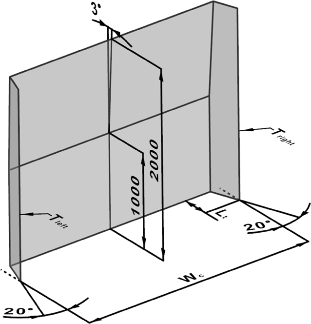
1.1.4. The intersections of the rear plane forming the side of the assessment zone with both angled outboard planes, lines T left and T right , shall be considered for the purpose of point 1.3.3.2. (see figure 2). U.K.
Figure 2 3D envelope U.K.
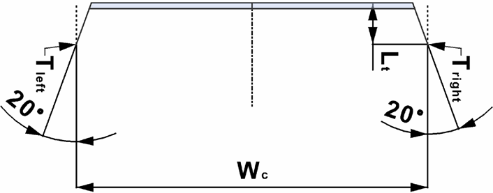
1.2. Horizontal boundaries of the motor vehicle cab assessment zone U.K.
1.2.1. In the assessment zone, the lower front fascia boundary line shall be set at ground level and the upper front fascia boundary line shall be set at 2 000 mm above the ground as measured in unladen condition. U.K.
1.3. Specific provisions for the motor vehicle cab assessment zone U.K.
1.3.1. For the purposes of this Appendix, the front fascia at the motor vehicle’s cab location shall be considered, regardless of type of material. However, the items listed in Appendix 1 shall not be taken into account. U.K.
1.3.2. Rake of the front of the cab U.K.
1.3.2.1. For the purposes of this Appendix, ‘ rake ’ shall be considered, meaning the rearward inclination of the motor vehicle’s front fascia at the cab location from the vertical, where any point located above another point lies rearward of that other point. U.K.
1.3.2.2. For the assessment zone of the rake, the most forward point of the motor vehicle’s cab location as referred to in point 1.1.3. shall be considered. U.K.
The vertical transverse plane through the most forward point of the cab, taken at a height of ≤ 2 000 mm from the ground measured in unladen condition, shall be considered as regards its intersection with the horizontal plane that is located at the height of 1 000 mm. The intersecting line shall then be taken as the base envelope line to assess the vehicle cab’s rake in the given assessment zone.
1.3.2.3. A plane rotating around the base envelope line referred to in the second paragraph of point 1.3.2.2., inclined rearward from the vertical by 3°, shall be taken (see figure 3). U.K.
Figure 3 Rake U.K.
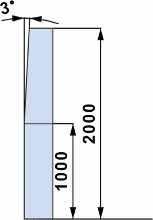
1.3.2.4. No point of the actual surface of the front fascia, as located in the assessment zone of the rake, shall lie forward of the rearward inclined plane referred to in point 1.3.2.3. when the most forward point of the motor vehicle’s cab location touches the vertical transverse plane. U.K.
1.3.3. Tapering of the sides of the motor vehicle cab. U.K.
1.3.3.1. In the assessment zone of the motor vehicle’s cab location, the front fascia shall be tapered in such a way that the relevant nominal surfaces generally converge towards a common area that lies forward of the cab and in the longitudinal median plane of the motor vehicle. U.K.
1.3.3.2. Two symmetrical vertical planes, one on the left side and one on the right side, shall be considered, both under a horizontal angle of 20° in relation to the longitudinal median plane and thus 40° apart. These planes are located in such a way that they also intersect with lines T left and T right referred to in point 1.1.3., respectively. U.K.
1.3.3.3. No point of the actual surface of the front fascia, as located in the left and right outboard zone, shall lie outward of the respective vertical plane referred to in point 1.3.3.2. with the most forward point of the motor vehicle’s cab location touching the vertical transverse plane referred to in point 1.3.2.4. U.K.
2. If any of the conditions set out in this Appendix are not met, it shall be considered that the motor vehicle cab does not conform to parameters of the three-dimensional envelope as referred to in point 1.4.1. of Part C of this Annex.] U.K.
ANNEX IIU.K.GRADEABILITY OF OFF-ROAD VEHICLES
1.GeneralU.K.
1.1.This Annex lays down the technical requirements for the purposes of verifying the gradeability of a vehicle in order to be categorised as off-road vehicle in accordance with Section 4 of Part A of [F73Annex I to Regulation (EU) 2018/858].U.K.Textual Amendments
F73Words in Annex 2 point 1.1 substituted (31.12.2022 at 11.00 p.m.) by The Road Vehicles and Non-Road Mobile Machinery (Type-Approval) (Amendment and Transitional Provisions) (EU Exit) Regulations 2022 (S.I. 2022/1273), regs. 1(2), 72(3)(a)
Textual Amendments
F73Words in Annex 2 point 1.1 substituted (31.12.2022 at 11.00 p.m.) by The Road Vehicles and Non-Road Mobile Machinery (Type-Approval) (Amendment and Transitional Provisions) (EU Exit) Regulations 2022 (S.I. 2022/1273), regs. 1(2), 72(3)(a)
1.2.The technical service shall verify if the complete or completed vehicle, or tractor unit for semi-trailer is to be considered as an off-road vehicle in accordance with the requirements laid down in [F74Annex I to Regulation (EU) 2018/858].U.K.Textual Amendments
F74Words in Annex 2 point 1.2 substituted (31.12.2022 at 11.00 p.m.) by The Road Vehicles and Non-Road Mobile Machinery (Type-Approval) (Amendment and Transitional Provisions) (EU Exit) Regulations 2022 (S.I. 2022/1273), regs. 1(2), 72(3)(b)
Textual Amendments
F74Words in Annex 2 point 1.2 substituted (31.12.2022 at 11.00 p.m.) by The Road Vehicles and Non-Road Mobile Machinery (Type-Approval) (Amendment and Transitional Provisions) (EU Exit) Regulations 2022 (S.I. 2022/1273), regs. 1(2), 72(3)(b)
1.3.For incomplete vehicles, this verification shall be carried out only at the request of the manufacturer.U.K.
2.Test conditionsU.K.
2.1.Vehicle conditionsU.K.
2.1.1.The vehicle shall be set in the conditions recommended by the manufacturer and fitted with the equipment referred to in [F75Annex I to Commission Implementing Regulation (EU) 2020/683].U.K.Textual Amendments
F75Words in Annex 2 point 2.1.1 substituted (31.12.2022 at 11.00 p.m.) by The Road Vehicles and Non-Road Mobile Machinery (Type-Approval) (Amendment and Transitional Provisions) (EU Exit) Regulations 2022 (S.I. 2022/1273), regs. 1(2), 72(3)(c)
Textual Amendments
F75Words in Annex 2 point 2.1.1 substituted (31.12.2022 at 11.00 p.m.) by The Road Vehicles and Non-Road Mobile Machinery (Type-Approval) (Amendment and Transitional Provisions) (EU Exit) Regulations 2022 (S.I. 2022/1273), regs. 1(2), 72(3)(c)
2.1.2.The adjustment of the brakes, clutch (or equivalent), engine and gear box shall be set in accordance with the manufacturer’s recommendations for the purposes of use off the normal roads.U.K.
2.1.3.The tyres shall be those recommended for off-roads use. They shall have a tread depth of not less than 90 % of the tread depth of a new tyre. The tyre pressure shall be adjusted to the value recommended by the tyre manufacturer.U.K.
2.1.4.The vehicle shall be loaded at its technically permissible maximum laden mass with a load distribution proportional to the distribution of the maximum mass on the axles as stated by the manufacturer.U.K.
For example a vehicle of 7,5 tonnes with a maximum mass on the front axle of 4 tonnes and a maximum mass on the rear axle of 6 tonnes shall be tested with a mass of 3 tonnes (40 %) on the front axle and 4,5 tonnes (60 %) on the rear axle.
2.2.Test track conditionsU.K.
2.2.1.The surface of the test track shall be dry, made of asphalt or concreteU.K.
2.2.2.The gradient shall show a continuous percentage of 25 % with a tolerance of + 3 % (θ = 14 degrees).U.K.
2.2.3.In agreement with the manufacturer, the test may be performed on a gradient that shows a percentage greater than 25 %. The test shall be conducted with maximum masses reduced in relation to the test conditions.U.K.
These conditions shall be reported.
2.2.4.The surface of the track shall show a good coefficient of adhesion.U.K.
The Skid Resistance Index (‘SRI’) of the surface shall be measured in accordance with Standard CEN/TS 13036-2: 2010 Road and airfield surface characteristics – Test methods – Part 2: Assessment of the skid resistance of a road pavement surface by use of dynamic measuring systems.
The mean value of the SRI shall be reported.
3.Test procedureU.K.
3.1.The vehicle shall be first placed on a horizontal surface.U.K.
3.2.The mode of traction shall be set as for off-roads use. The gear(s) engaged shall allow a steady speed.U.K.
3.3.Sections 4 and 5 of Appendix 1 to [F76Annex I to Regulation (EU) 2018/858] shall apply.U.K.Textual Amendments
F76Words in Annex 2 point 3.3 substituted (31.12.2022 at 11.00 p.m.) by The Road Vehicles and Non-Road Mobile Machinery (Type-Approval) (Amendment and Transitional Provisions) (EU Exit) Regulations 2022 (S.I. 2022/1273), regs. 1(2), 72(3)(d)
Textual Amendments
F76Words in Annex 2 point 3.3 substituted (31.12.2022 at 11.00 p.m.) by The Road Vehicles and Non-Road Mobile Machinery (Type-Approval) (Amendment and Transitional Provisions) (EU Exit) Regulations 2022 (S.I. 2022/1273), regs. 1(2), 72(3)(d)
ANNEX IIIU.K. CONDITIONS OF EQUIVALENCE OF A SUSPENSION TO AIR-SUSPENSION
1.This Annex lays down the technical conditions relating to the equivalence of a suspension to air-suspension for vehicle driving axle(s).U.K.
2.In order to be recognised as equivalent to air suspension, a suspension shall comply with the following requirements:U.K.
2.1.
During free transient low-frequency vertical oscillation of the sprung mass above a driving axle or group of axles, the measured frequency and damping with the suspension carrying its maximum load shall fall within the limits defined in points 2.3 to 2.6
2.2.
Each axle shall be fitted with hydraulic dampers. On groups of axles, the dampers shall be positioned to minimise the oscillation of the groups of axles.
2.3.
The mean damping ratio Dm shall be more than 20 % of critical damping for the suspension in its normal condition with hydraulic dampers in place and operating.
2.4.
The damping ratio Dr of the suspension with all hydraulic dampers removed or incapacitated shall be not more than 50 % of Dm.
2.5.
The frequency of the sprung mass above the driving axle or group of axles in a free transient vertical oscillation shall not be higher than 2,0 Hz.
2.6.
The test procedures for measuring the frequency and damping shall be laid down in point 3.
3. Test procedure U.K.
3.1. Frequency and damping U.K.
3.1.1.The free oscillation of the sprung mass shall be given by the following equation:U.K.

Where
‘M’ is the sprung mass (kg),
‘Z’ is the vertical displacement of the sprung mass (m),
‘C’ is the total damping coefficient (N.s/m) and
‘K’ is the total vertical stiffness between the road surface and the sprung mass (N/m).
3.1.2.The frequency of oscillation (‘F’ in Hz) of the sprung mass shall be given by the following equation:U.K.

3.1.3.The damping is critical when C = CoU.K.
where:

The damping ratio as a fraction of critical is C/Co.
3.1.4.During free transient oscillation of the sprung mass the vertical motion of the mass will follow a damped sinusoidal path (Figure 2). The frequency can be estimated by measuring the time for as many cycles of oscillation as can be observed. The damping can be estimated by measuring the heights of successive peaks of the oscillation in the same direction.U.K.
3.1.5.If the peak amplitudes of the first and second cycles of the oscillation are A 1 and A2, then the damping ratio D is given by the following equation:U.K.

‘ln’ being the natural logarithm of the amplitude ratio.
3.2. Test procedure U.K.
To establish by test the damping ratio Dm, the damping ratio Dr, with hydraulic dampers removed, and the frequency F of the suspension, the loaded vehicle shall be either:
(a)
driven at low speed (5 km/h ± 1 km/h) over an 80 mm step with the profile shown in Figure 1. The transient oscillation to be analysed for frequency and damping occurs after the wheels of the driving axle have left the step;
(b)
pulled down by its chassis so that the driving axle load is 1,5 times its maximum static value. The vehicle held down is suddenly released and the subsequent oscillation analysed;
(c)
pulled up by its chassis so that the sprung mass is lifted by 80 mm above the driving axle. The vehicle held up is suddenly dropped and the subsequent oscillation analysed;
(d)
subjected to other procedures insofar as it has been proved by the manufacturer, to the satisfaction of the technical service, that they are equivalent.
3.3. Test equipment of the vehicle and loading conditions U.K.
3.3.1The vehicle shall be fitted with a vertical displacement transducer between driving axle and chassis, directly above the driving axle. From the trace, the time interval between the first and second compression peaks shall be measured to obtain the damping.U.K.
For twin driving groups of axles, vertical displacement transducers shall be fitted between each driving axle and the chassis directly above it.
3.3.2.The tyres shall be inflated to the appropriate pressure recommended by the manufacturer.U.K.
3.3.3The test for verifying the equivalence of the suspensions shall be made at the technically permissible maximum mass on the axle or group of axles, and the equivalence assumed to cover all the lower masses.U.K.


ANNEX IVU.K. TECHNICAL REQUIREMENTS FOR THE INSTALLATION OF LIFT- OR LOADABLE AXLE(S) ON VEHICLES
1.If a vehicle is fitted with one or more lift- or loadable axles it shall be ensured that under normal driving conditions the registration/in-service maximum permissible masses on solo axles or groups of axles are not exceeded. To that end the lift- or loadable axle(s) shall be lowered to the ground or be loaded automatically if the nearest axle(s) of the group or the front axle(s) of the motor vehicle is/are laden to its/their registration/in- service maximum permissible mass(es).U.K.
Where a lift axle is in elevated position, it shall be ensured that the mass on the steering axle(s) continues to be sufficient to ensure the safe driving of the vehicle in all circumstances. For such purposes, the vehicle manufacturer shall specify, in the case of incomplete vehicles, the minimum mass on the steering axle(s).
2.Every axle-lift device fitted to a vehicle, as well as the systems for its operation, shall be designed and installed in such a manner as to protect them against any improper use or tampering.U.K.
3.Requirements for moving off vehicles on slippery surfaces and to improve their manoeuvrabilityU.K.
3.1.By way of derogation from the requirements of point 1 and to help motor vehicles or vehicle combinations to move off on slippery ground and to increase the traction of the tyres on these surfaces as well to improve their manoeuvrability, the axle lift device may actuate the lift- or loadable axle(s) of a motor vehicle or semi-trailer to increase or decrease the mass on the driving axle of the motor vehicle, subject to the following conditions:U.K.
(a)
the mass corresponding to the load on each axle of the vehicle may exceed the maximum authorised mass on the axle in force in the Member State by up to 30 % provided it does not exceed the value stated by the manufacturer for this special purpose;
(b)
the mass corresponding to the remaining load on the front axle(s) shall remain above zero (i.e. in case of a rear loadable axle with long rear overhang, the vehicle may not tip up);
(c)
the lift- or loadable axle(s) shall be actuated only by a specific control;
(d)
after the vehicle has moved off and before its speed exceeds 30 km/h, the axle(s) shall automatically be lowered again to the ground or be reloaded.
ANNEX VU.K.
[F1PART AU.K. [F77GB] type-approval of motor vehicles and their trailers with regard to the masses and dimensions of a vehicle INFORMATION DOCUMENT MODEL]
Information document No … relating to the [F78GB type-approval] of a motor vehicle and their trailers with regard the masses and dimensions of a vehicle.U.K.
Textual Amendments
F78Words in Annex 5 Pt. A substituted (31.12.2022 at 11.00 p.m.) by The Road Vehicles and Non-Road Mobile Machinery (Type-Approval) (Amendment and Transitional Provisions) (EU Exit) Regulations 2022 (S.I. 2022/1273), regs. 1(2), 72(4)(b)(i)
The following information shall be supplied in triplicate and include a list of contents. Any drawings shall be supplied in appropriate scale and in sufficient detail on size A4 or on a folder of A4 format. Photographs, if any, shall show sufficient detail.
0.GENERALU.K.
0.1.Make (trade name of manufacturer): …U.K.
0.2.Type: …U.K.
0.2.1.Commercial name(s) (if available): …U.K.
0.4.Category of vehicle (c): …U.K.
0.5.Company name and address of manufacturer: …U.K.
0.8.Name(s) and address(es) of assembly plant(s): …U.K.
0.9.Name and address of the manufacturer’s representative (if any): …U.K.
1.GENERAL CONSTRUCTION CHARACTERISTICS OF THE VEHICLEU.K.
1.1.Photographs and/or drawings of a representative vehicle: …U.K.
1.2.Dimensional drawing of the whole vehicle: …U.K.
1.3.Number of axles and wheels: …U.K.
1.3.1.Number and position of axles with twin wheels: …U.K.
1.3.2.Number and position of steered axles: …U.K.
1.3.3.Powered axles (number, position, interconnection): …U.K.
1.4.Chassis (if any) (overall drawing): …U.K.
1.7.Driving cab (forward control or bonneted) (e): …U.K.
1.9.Specify if the towing vehicle is intended to tow semi-trailers or other trailers and, if the trailer is a semi-, drawbar-, centre-axle- or rigid drawbar trailer: …U.K.
1.10.Specify if the vehicles is specially designed for the controlled-temperature carriage of goods: …U.K.
2.MASSES AND DIMENSIONS (f)(g)(7)U.K.
(in kg and mm) (Refer to drawing where applicable)
2.1.Wheel base(s) (fully loaded) (g1): …U.K.
2.1.1.Two-axle vehicles: …U.K.
2.1.2.Vehicles with three or more axlesU.K.
2.1.2.1.Axle spacing between consecutive axles going from the foremost to the rearmost axle: …U.K.
2.1.2.2.Total axle spacing: …U.K.
2.2.Fifth wheelU.K.
2.2.1.In the case of semi-trailersU.K.
2.2.1.1.Distance between the axis of the fifth wheel kingpin and the rearmost end of the semi-trailer: …U.K.
2.2.1.2.Maximum distance between the axis of the fifth wheel king pin and any point on the front of the semi-trailer: …U.K.
2.2.1.3.Semi-trailer reference wheelbase (as required in point 3.2 of Part D of Annex I to Regulation (EU) No 1230/2012: …U.K.
2.2.2.In the case of semi-trailer towing vehiclesU.K.
2.2.2.1.Fifth wheel lead (maximum and minimum; indicate the permissible values in the case of an incomplete vehicle) (g2): …U.K.
2.3.Axle track(s) and width(s)U.K.
2.3.1.Track of each steered axle (g4): …U.K.
2.3.2.Track of all other axles (g4): …U.K.
2.4.Range of vehicle dimensions (overall)U.K.
2.4.1.For chassis without bodyworkU.K.
2.4.1.1.Length (g5): …U.K.
2.4.1.1.1.Maximum permissible length: …U.K.
2.4.1.1.2.Minimum permissible length: …U.K.
2.4.1.1.3.In the case of trailers, maximum permissible drawbar length (g6): …U.K.
2.4.1.2.Width (g7): …U.K.
2.4.1.2.1.Maximum permissible width: …U.K.
2.4.1.2.2.Minimum permissible width: …U.K.
2.4.1.3.Height (g8) (for suspensions adjustable for height, indicate normal running position): …U.K.
2.4.1.4.Front overhang (g9): …U.K.
2.4.1.4.1.Approach angle (g10) (4): … degrees.U.K.
2.4.1.5.Rear overhang (g11): …U.K.
2.4.1.5.1.Departure angle (g12) (4): … degrees.U.K.
2.4.1.5.2.Minimum and maximum permissible overhang of the coupling point (g13): …U.K.
2.4.1.6.Ground clearance (as defined in points 3.1.1 and 3.2.1 of Appendix 1 to Annex II to Directive 2007/46/EC)U.K.
2.4.1.6.1.Between the axles: …U.K.
2.4.1.6.2.Under the front axle(s): …U.K.
2.4.1.6.3.Under the rear axle(s): …U.K.
2.4.1.8.Position of the centre of gravity of the bodywork and/or interior fittings and/or equipment and/or pay-mass (minimum and maximum): …U.K.
2.4.2.For chassis with bodyworkU.K.
2.4.2.1.Length (g5): …U.K.
2.4.2.1.1.Length of the loading area: …U.K.
[F92.4.2.1.3.Elongated cab complying to [F79point 1.4 of Part C of Annex I to Commission Regulation (EU) No 2012/1230]: yes/no ( 1 )]U.K.Textual Amendments
F79Words in Annex 5 Pt. A point 2.4.2.1.3 substituted (31.12.2022 at 11.00 p.m.) by The Road Vehicles and Non-Road Mobile Machinery (Type-Approval) (Amendment and Transitional Provisions) (EU Exit) Regulations 2022 (S.I. 2022/1273), regs. 1(2), 72(4)(b)(ii)
Textual Amendments
F79Words in Annex 5 Pt. A point 2.4.2.1.3 substituted (31.12.2022 at 11.00 p.m.) by The Road Vehicles and Non-Road Mobile Machinery (Type-Approval) (Amendment and Transitional Provisions) (EU Exit) Regulations 2022 (S.I. 2022/1273), regs. 1(2), 72(4)(b)(ii)
2.4.2.2.Width (g7): …U.K.
2.4.2.2.1.Thickness of the walls (in the case of vehicles designed for controlled-temperature carriage of goods): …U.K.
2.4.2.3.Height (g8) (for suspensions adjustable for height, indicate normal running position): …U.K.
2.4.2.4.Front overhang (g9): …U.K.
2.4.2.4.1.Approach angle (g10) (4): … degrees.U.K.
2.4.2.5.Rear overhang (g11): …U.K.
2.4.2.5.1.Departure angle (g12) (4): … degrees.U.K.
2.4.2.5.2.Minimum and maximum permissible overhang of the coupling point (g13): …U.K.
2.4.2.6.Ground clearance (as defined in [F80points 4.1 and 4.2 of Part A of Annex I to Regulation (EU) 2018/858]) (4)U.K.
2.4.2.6.1.Between the axles: …U.K.
2.4.2.6.2.Under the front axle(s): …U.K.
2.4.2.6.3.Under the rear axle(s): …U.K.
Textual Amendments
F80Words in Annex 5 Pt. A point 2.4.2.6 substituted (31.12.2022 at 11.00 p.m.) by The Road Vehicles and Non-Road Mobile Machinery (Type-Approval) (Amendment and Transitional Provisions) (EU Exit) Regulations 2022 (S.I. 2022/1273), regs. 1(2), 72(4)(b)(iii)
2.4.2.8.Positions of the centre of gravity of the pay-mass (in the case of non-uniform load): …U.K.
2.4.3.For bodywork approved without chassis (vehicles M2 and M3)U.K.
2.4.3.1.Length (g5): …U.K.
2.4.3.2.Width (g7): …U.K.
2.4.3.3.Height (g8) on intended chassis type(s) (for suspensions adjustable for height, indicate normal running position): …U.K.
2.5.Minimum mass on the steering axle(s) for incomplete vehicles: …U.K.
2.6. Mass in running order (h) U.K.
(a)minimum and maximum for each variant: …U.K.
2.6.1.Distribution of this mass among the axles and, in the case of a semi-trailer, centre-axle trailer or rigid drawbar trailer, the mass on the coupling point: …U.K.
(a)minimum and maximum for each variant: …U.K.
2.6.2.Mass of the optional equipment (see definition No 5 of Article 2 of Regulation (EU) No 1230/2012: …U.K.
[F92.6.4.F81Additional mass for alternative propulsion: … kg]U.K.Textual Amendments
F81Annex 5 Pt. A point 2.6.4: by The Road Vehicles and Non-Road Mobile Machinery (Type-Approval) (Amendment and Transitional Provisions) (EU Exit) Regulations 2022 (S.I. 2022/1273), regs. 1(2), 72(4)(b)(iv) it is provided that the words "Increase in mass" are substituted (31.12.2022 at 11.00 p.m.) for “Additional weight”
Textual Amendments
F81Annex 5 Pt. A point 2.6.4: by The Road Vehicles and Non-Road Mobile Machinery (Type-Approval) (Amendment and Transitional Provisions) (EU Exit) Regulations 2022 (S.I. 2022/1273), regs. 1(2), 72(4)(b)(iv) it is provided that the words "Increase in mass" are substituted (31.12.2022 at 11.00 p.m.) for “Additional weight”
2.8.Technically permissible maximum laden mass (i): …U.K.
2.8.1.Distribution of this mass among the axles and, in the case of a semi-trailer, centre-axle trailer or rigid drawbar trailer, load on the coupling point: …U.K.
2.9.Technically permissible maximum mass on each axle: …U.K.
2.10.Technically permissible maximum mass on each group of axles: …U.K.
2.11.Technically permissible maximum towable mass of the towing vehicleU.K.
in case of:
2.11.1.Drawbar trailer: …U.K.
2.11.2.Semi-trailer: …U.K.
2.11.3.Centre-axle trailer: …U.K.
[F822.11.3.1.]Maximum ratio of the coupling overhang (j) to the wheel base: …U.K.
Textual Amendments
F82Annex 5 Pt. A point 2.11.4.1 renumbered as Annex 5 Pt. A point 2.11.3.1 (31.12.2022 at 11.00 p.m.) by The Road Vehicles and Non-Road Mobile Machinery (Type-Approval) (Amendment and Transitional Provisions) (EU Exit) Regulations 2022 (S.I. 2022/1273), regs. 1(2), 72(4)(b)(v)
[F832.11.3.2.]Maximum V-value: … kN.U.K.
Textual Amendments
F83Annex 5 Pt. A point 2.11.4.2 renumbered as Annex 5 Pt. A point 2.11.3.2 (31.12.2022 at 11.00 p.m.) by The Road Vehicles and Non-Road Mobile Machinery (Type-Approval) (Amendment and Transitional Provisions) (EU Exit) Regulations 2022 (S.I. 2022/1273), regs. 1(2), 72(4)(b)(vi)
2.11.4.Rigid drawbar trailer: …U.K.
2.11.5.Technically permissible maximum laden mass of the combination: …U.K.
2.11.6.Maximum mass of unbraked trailer: …U.K.
2.12.Technically permissible maximum mass at the coupling point:U.K.
2.12.1.of a towing vehicle: …U.K.
2.12.2.of a semi-trailer, a centre-axle trailer or a rigid drawbar trailer: …U.K.
2.12.3.Maximum permissible mass of the coupling device (if not fitted by the manufacturer): …U.K.
2.16.Intended registration/in service maximum permissible masses (optional)U.K.
2.16.1.Registration/in service maximum permissible laden mass (5): …U.K.
2.16.2.Registration/in service maximum permissible mass on each axle and, in the case of a semi-trailer or centre-axle trailer, intended load on the coupling point stated by the manufacturer if lower than the technically permissible maximum mass on the coupling point (5): …U.K.
2.16.3.Registration/in service maximum permissible mass on each group of axles (5): …U.K.
2.16.4.Registration/in service maximum permissible towable mass (5): …U.K.
2.16.5.Registration/in service maximum permissible mass of the combination (5): …U.K.
3.POWER PLANT (k)U.K.
3.1.Manufacturer of the engine: …U.K.
3.2.Internal combustion engineU.K.
3.2.1.8.Maximum net power (n): … kW at … min–1 (manufacturer’s declared value)U.K.
Note:for the purposes of this Regulation, it is permitted to refer to the engine that shows the lowest powerU.K.
3.3.Electric motorU.K.
3.3.1.1.Maximum hourly output: … kWU.K.
3.4.Engine or motor combinationU.K.
3.4.1.Hybrid electric vehicle: yes/no (1)U.K.
3.4.5.4.Maximum power: … kWU.K.
[F93.9. List of equipment to for alternative propulsion (and indication of the mass of the parts): …]U.K.
4.TRANSMISSION (p)U.K.
4.1.Drawing of the transmission (4): …U.K.
5.AXLESU.K.
5.1.Description of each axle: …U.K.
5.2.Make: …U.K.
5.3.Type: …U.K.
5.4.Position of lift axle(s): …U.K.
5.5.Position of loadable axle(s): …U.K.
6.SUSPENSIONU.K.
6.1.Drawing of the suspension arrangements: …U.K.
6.2.Type and design of the suspension of each axle or group of axles or wheel: …U.K.
6.2.3.Air-suspension for driving axle(s): yes/no (1)U.K.
6.2.3.1.Suspension of driving axle(s) equivalent to air-suspension: yes/no (1)U.K.
6.2.3.2.Frequency and damping of the oscillation of the sprung mass: …U.K.
6.2.4.Air-suspension for non-driving axle(s): yes/no (1)U.K.
6.2.4.1.Suspension of non-driving axle(s) equivalent to air-suspension: yes/no (1)U.K.
6.2.4.2.Frequency and damping of the oscillation of the sprung mass: …U.K.
6.3.Distribution of the mass between the axles which are part of a group of axles (where necessary, provide appropriate graphs): …U.K.
6.6.Tyres and wheelsU.K.
6.6.1.Tyre/wheel combination(s) (r)U.K.
(a)
for tyres indicate
(i)
size designation: …
(ii)
load-capacity index: …
(iii)
speed category symbol: …
6.6.1.1.AxlesU.K.
6.6.1.1.1.Axle 1: …U.K.
6.6.1.1.2.Axle 2: …U.K.
etc.
9.BODYWORKU.K.
9.1.Type of bodywork using the codes defined in Part C of [F84Annex I to Regulation (EU) 2018/858]: …U.K.Textual Amendments
F84Words in Annex 5 Pt. A point 9.1 substituted (31.12.2022 at 11.00 p.m.) by The Road Vehicles and Non-Road Mobile Machinery (Type-Approval) (Amendment and Transitional Provisions) (EU Exit) Regulations 2022 (S.I. 2022/1273), regs. 1(2), 72(4)(b)(vii)
Textual Amendments
F84Words in Annex 5 Pt. A point 9.1 substituted (31.12.2022 at 11.00 p.m.) by The Road Vehicles and Non-Road Mobile Machinery (Type-Approval) (Amendment and Transitional Provisions) (EU Exit) Regulations 2022 (S.I. 2022/1273), regs. 1(2), 72(4)(b)(vii)
9.10.3.SeatsU.K.
9.10.3.1.Number of seating positions (s): …U.K.
9.10.3.1.1.Location and arrangement: …U.K.
9.10.3.5.Coordinates or drawing of the R-point (t)U.K.
9.10.3.5.1.Driver’s seat: …U.K.
9.10.3.5.2.All other seating positions: …U.K.
[F19.25. Elongated Cabs complying to [F85point 1.4 of Part C of Annex I to Commission Regulation 2012/1230] U.K.
9.25.1. Detailed technical description (including photographs and drawings, as well as description of the materials) of the vehicle parts relevant to Part C, point 1.4 of Annex I to Regulation (EU) No 1230/2012: … U.K.
Textual Amendments
F85Words in Annex 5 Pt. A point 9.25 substituted (31.12.2022 at 11.00 p.m.) by The Road Vehicles and Non-Road Mobile Machinery (Type-Approval) (Amendment and Transitional Provisions) (EU Exit) Regulations 2022 (S.I. 2022/1273), regs. 1(2), 72(4)(b)(viii)
9.26. Aerodynamic device or equipment on the front of the vehicle U.K.
9.26.1. Vehicle equipped with aerodynamic device or equipment on the front: yes/no( 1 ) U.K.
9.26.2. Type-approval number of the aerodynamic device or equipment, if available: … or, if not available: U.K.
9.26.3. Detailed description (including photographs or drawings) of the aerodynamic device or equipment U.K.
9.26.3.1.Construction and materials: …U.K.
9.26.3.2.Locking and adjustment system: …U.K.
9.26.3.3.Attachment and mounting to the vehicle: …U.K.
9.27. Aerodynamic device or equipment on the rear of the vehicle U.K.
9.27.1. Vehicle equipped with aerodynamic device or equipment on the rear: yes/no( 1 ) U.K.
9.27.2. Type-approval number of the aerodynamic device or equipment, if available ... or, if not available: U.K.
9.27.3. Detailed description (including photographs or drawings) of the aerodynamic device or equipment U.K.
9.27.3.1.Construction and materials: …U.K.
9.27.3.2.Locking and adjustment system: …U.K.
9.27.3.3.Attachment and mounting to the vehicle: …]U.K.
11.CONNECTIONS BETWEEN TOWING VEHICLES AND TRAILERS AND SEMI-TRAILERSU.K.
11.1.Class and type of the coupling device(s) fitted or to be fitted: …U.K.
11.2.Characteristics D, U, S and V of the coupling device(s) fitted or minimal characteristics D, U, S and V of the coupling device(s) to be fitted: … daNU.K.
13.SPECIAL PROVISIONS FOR BUSES AND COACHESU.K.
13.1.Class of vehicle: Class I/Class II/Class III/Class A/Class B (1)U.K.
13.2.Area for passengers (m2)U.K.
13.2.1.Total (S0): …U.K.
13.2.2.Upper deck (S0a) (1): …U.K.
13.2.3.Lower deck (S0b) (1): …U.K.
13.2.4.For standing passengers (S1): …U.K.
13.3.Number of passengers (seated and standing)U.K.
13.3.1.Total (N): …U.K.
13.3.2.Upper deck (Na) (1): …U.K.
13.3.3.Lower deck (Nb) (1): …U.K.
13.4.Number of passengers seatedU.K.
13.4.1.Total (A): …U.K.
13.4.2.Upper deck (Aa) (1): …U.K.
13.4.3.Lower deck (Ab) (1): …U.K.
13.4.4.Number of wheelchair positions for category M2 and M3 vehicles: …U.K.
13.7.Volume of luggage compartments (m3): …U.K.
13.12.Drawing with dimensions showing the interior arrangement as regards the seating positions, area for standees, wheelchair user(s), luggage compartments including racks and ski-box, if anyU.K.
Explanatory notesU.K.
(1) Delete where not applicable (there are cases where nothing needs to be deleted when more than one entry is applicable).
(4) Only for the purpose of definition of off-road vehicles.
(5) Set out in such a way as to make the actual value clear for each technical configuration of the vehicle type.
(7) Optional equipment that affects the dimensions of the vehicle shall be specified. (b) If the means of identification of type contains characters not relevant to describe the vehicle, component or separate technical unit types covered by this information document, such characters shall be represented in the documentation by the symbol ‘?’(e.g. ABC??123??).
(c) Classified according to the definitions set out in [F86Article 4 of Regulation (EU) 2018/858].
[F87(e) ‘Forward control’ means a configuration in which more than half of the engine length is rearward of the foremost point of the windshield base and the steering wheel hub in the forward quarter of the vehicle length as defined in the explanatory note (z) of Appendix 1 of Part 1 of Annex 1 to UN Regulation No 107, as amended by the 07 series of amendments.]
(f) Where there is one version with a normal cab and another with a sleeper cab, both sets of masses and dimensions are to be stated
(g) Standard ISO 612: 1978 – Road vehicles – Dimensions of motor vehicles and towed vehicles – terms and definitions.
(g1) — term No 6.4.
(g2) — term No 6.19.2.
(g3) — term No 6.20.
(g4) — term No 6.5.
(g5) — term No 6.1 and for vehicles other than those of category M1. In the case of trailers, the lengths shall be specified as mentioned in term No 6.1.2 of Standard ISO 612: 1978.
(g6) — term No 6.17.
(g7) — term No 6.2 and for vehicles other than those of category M1.
(g8) — term No 6.3 and for vehicles other than those of category M1.
(g9) — term No 6.6.
(g10) — term No 6.10.
(g11) — term No 6.7.
(g12) — term No 6.11.
(g13) — term No 6.18.1.
(g14) — term No 6.9.
(h) The mass of the driver is assessed at 75 kg. The liquid containing systems (except those for used water that must remain empty) are filled to 100 % of the capacity specified by the manufacturer.
The information referred to in points 2.6(a) and 2.6.1(a) do not need to be provided for vehicle categories N2, N3, M2, M3, O3, and O4.
(i) For trailers or semi-trailers, and for vehicles coupled with a trailer or a semi-trailer, which exert a significant vertical load on the coupling device or the fifth wheel, this load, divided by standard acceleration of gravity, is included in the maximum technically permissible mass.
(j) ‘Coupling overhang’ is the horizontal distance between the coupling for centre-axle trailers and the centreline of the rear axle(s).
(k) In the case of a vehicle that can run either on petrol, diesel, etc., or also in combination with another fuel, items shall be repeated.
In the case of non-conventional engines and systems, particulars equivalent to those referred to here shall be supplied by the manufacturer.
(l) This figure shall be rounded off to the nearest tenth of a millimetre.
(n) Determined in accordance with the requirements of [F88Regulation (EC) No 715/2007 or Regulation (EC) No 595/2009 as applicable].
(o) Determined in accordance with the requirements of [F89Regulation (EC) No 715/2007].
(p) The specified particulars are to be given for any proposed variants. (r) For tyres of category Z intended to be fitted on vehicles whose maximum speed exceeds 300 km/h equivalent information shall beprovided.
(s) The number of seating positions to be mentioned shall be the one when the vehicle is in motion. A range can be specified in case of modular arrangement.
(t) ‘R-point’ or ‘seating reference point’ means a design point defined by the vehicle manufacturer for each seating position and established with respect to the three-dimensional reference system as specified in [F90Annex III to UN Regulation No 17, as amended by the 08 series of amendments].
Textual Amendments
F86Words in Annex 5 Pt. A substituted (31.12.2022 at 11.00 p.m.) by The Road Vehicles and Non-Road Mobile Machinery (Type-Approval) (Amendment and Transitional Provisions) (EU Exit) Regulations 2022 (S.I. 2022/1273), regs. 1(2), 72(4)(b)(ix)(aa)
F87Words in Annex 5 Pt. A substituted (31.12.2022 at 11.00 p.m.) by The Road Vehicles and Non-Road Mobile Machinery (Type-Approval) (Amendment and Transitional Provisions) (EU Exit) Regulations 2022 (S.I. 2022/1273), regs. 1(2), 72(4)(b)(ix)(bb)
F88Words in Annex 5 Pt. A substituted (31.12.2022 at 11.00 p.m.) by The Road Vehicles and Non-Road Mobile Machinery (Type-Approval) (Amendment and Transitional Provisions) (EU Exit) Regulations 2022 (S.I. 2022/1273), regs. 1(2), 72(4)(b)(ix)(cc)
F89Words in Annex 5 Pt. A substituted (31.12.2022 at 11.00 p.m.) by The Road Vehicles and Non-Road Mobile Machinery (Type-Approval) (Amendment and Transitional Provisions) (EU Exit) Regulations 2022 (S.I. 2022/1273), regs. 1(2), 72(4)(b)(ix)(dd)
F90Words in Annex 5 Pt. A substituted (31.12.2022 at 11.00 p.m.) by The Road Vehicles and Non-Road Mobile Machinery (Type-Approval) (Amendment and Transitional Provisions) (EU Exit) Regulations 2022 (S.I. 2022/1273), regs. 1(2), 72(4)(b)(ix)(ee)
Textual Amendments
F77Word in Annex 5 Pt. A heading substituted (31.12.2022 at 11.00 p.m.) by The Road Vehicles and Non-Road Mobile Machinery (Type-Approval) (Amendment and Transitional Provisions) (EU Exit) Regulations 2022 (S.I. 2022/1273), regs. 1(2), 72(4)(a)
[F1PART BU.K. [F91GB type-approval] certificate of motor vehicles and their trailers with regard to the masses and dimensions of vehicles
MODEL U.K. Format: A4 (210 × 297 mm) U.K. [F91GB type-approval] CERTIFICATE]U.K.
Stamp of type-approval authority
[F92Communication concerning granting / extension / refusal / withdrawal (7) of type-approval of a type of vehicle with regard to its masses and dimensions in accordance with the requirements laid down in Commission Regulation (EU) 2012/1230 as it has effect in domestic law, as last amended by SI_____/_____.
Textual Amendments
F92Words in Annex 5 Pt. B substituted (31.12.2022 at 11.00 p.m.) by The Road Vehicles and Non-Road Mobile Machinery (Type-Approval) (Amendment and Transitional Provisions) (EU Exit) Regulations 2022 (S.I. 2022/1273), regs. 1(2), 72(4)(c)(ii)
Number of the GB type-approval certificate:
Reason for extension / refusal / withdrawal (14):]
SECTION IU.K.
[F93(to be completed in accordance with Section I of the template of Model B in Annex III to Commission Implementing Regulation (EU) 2020/683)]
Textual Amendments
F93Words in Annex 5 Pt. B s. 1 substituted (31.12.2022 at 11.00 p.m.) by The Road Vehicles and Non-Road Mobile Machinery (Type-Approval) (Amendment and Transitional Provisions) (EU Exit) Regulations 2022 (S.I. 2022/1273), regs. 1(2), 72(4)(c)(iii)
SECTION IIU.K.
[F94(to be completed in accordance with Section II of the template of Model B in Annex III to Commission Implementing Regulation (EU) 2020/683)]
Textual Amendments
F94Words in Annex 5 Pt. B s. 2 substituted (31.12.2022 at 11.00 p.m.) by The Road Vehicles and Non-Road Mobile Machinery (Type-Approval) (Amendment and Transitional Provisions) (EU Exit) Regulations 2022 (S.I. 2022/1273), regs. 1(2), 72(4)(c)(iv)
[F1Addendum to [F95GB type-approval] certificate No ... U.K.
1.[F96Additional information]U.K.Textual Amendments
F96Words in Annex 5 Pt. B Addendum substituted (31.12.2022 at 11.00 p.m.) by The Road Vehicles and Non-Road Mobile Machinery (Type-Approval) (Amendment and Transitional Provisions) (EU Exit) Regulations 2022 (S.I. 2022/1273), regs. 1(2), 72(4)(c)(v)(bb)
Textual Amendments
F96Words in Annex 5 Pt. B Addendum substituted (31.12.2022 at 11.00 p.m.) by The Road Vehicles and Non-Road Mobile Machinery (Type-Approval) (Amendment and Transitional Provisions) (EU Exit) Regulations 2022 (S.I. 2022/1273), regs. 1(2), 72(4)(c)(v)(bb)
1.1.The vehicle has been type-approved in accordance with Article 6(1) [F97or 6(2)] of this Regulation (i.e. the outermost dimensions of the vehicle exceeds the maximum dimensions mentioned in Part A, B, C or D of Annex I): yes/no(14)U.K.Textual Amendments
F97Words in Annex 5 Pt. B Addendum inserted (31.12.2022 at 11.00 p.m.) by The Road Vehicles and Non-Road Mobile Machinery (Type-Approval) (Amendment and Transitional Provisions) (EU Exit) Regulations 2022 (S.I. 2022/1273), regs. 1(2), 72(4)(c)(v)(cc)
Textual Amendments
F97Words in Annex 5 Pt. B Addendum inserted (31.12.2022 at 11.00 p.m.) by The Road Vehicles and Non-Road Mobile Machinery (Type-Approval) (Amendment and Transitional Provisions) (EU Exit) Regulations 2022 (S.I. 2022/1273), regs. 1(2), 72(4)(c)(v)(cc)
[F981.1.1Vehicle intended for transport of indivisible loads only: yes / no]U.K.
Textual Amendments
F98Words in Annex 5 Pt. B Addendum inserted (31.12.2022 at 11.00 p.m.) by The Road Vehicles and Non-Road Mobile Machinery (Type-Approval) (Amendment and Transitional Provisions) (EU Exit) Regulations 2022 (S.I. 2022/1273), regs. 1(2), 72(4)(c)(v)(dd)
1.2.[F99The vehicle has been type-approved in accordance with paragraphs 1.3.1.1 or 1.3.1.2 of Part C of Annex I to Commission Regulation (EU) 2012/1230 (i.e. aerodynamic devices or equipment at the rear of the vehicle): yes / no:]U.K.Textual Amendments
F99Words in Annex 5 Pt. B Addendum substituted (31.12.2022 at 11.00 p.m.) by The Road Vehicles and Non-Road Mobile Machinery (Type-Approval) (Amendment and Transitional Provisions) (EU Exit) Regulations 2022 (S.I. 2022/1273), regs. 1(2), 72(4)(c)(v)(ee)
Textual Amendments
F99Words in Annex 5 Pt. B Addendum substituted (31.12.2022 at 11.00 p.m.) by The Road Vehicles and Non-Road Mobile Machinery (Type-Approval) (Amendment and Transitional Provisions) (EU Exit) Regulations 2022 (S.I. 2022/1273), regs. 1(2), 72(4)(c)(v)(ee)
1.3.[F100The vehicle has been type-approved in accordance with paragraphs 1.3.1.3 or 1.4 of Part C of Annex I to Commission Regulation (EU) 2012/1230 (i.e. a cab fitted with aerodynamic devices or equipment or an elongated cab): yes / no:]U.K.Textual Amendments
F100Words in Annex 5 Pt. B Addendum substituted (31.12.2022 at 11.00 p.m.) by The Road Vehicles and Non-Road Mobile Machinery (Type-Approval) (Amendment and Transitional Provisions) (EU Exit) Regulations 2022 (S.I. 2022/1273), regs. 1(2), 72(4)(c)(v)(ee)
Textual Amendments
F100Words in Annex 5 Pt. B Addendum substituted (31.12.2022 at 11.00 p.m.) by The Road Vehicles and Non-Road Mobile Machinery (Type-Approval) (Amendment and Transitional Provisions) (EU Exit) Regulations 2022 (S.I. 2022/1273), regs. 1(2), 72(4)(c)(v)(ee)
1.4.The vehicle has been type-approved [F101in accordance with Regulation 4 of the Road Vehicles (Authorised Weight) Regulations 1998]:U.K.Textual Amendments
F101Words in Annex 5 Pt. B Addendum substituted (31.12.2022 at 11.00 p.m.) by The Road Vehicles and Non-Road Mobile Machinery (Type-Approval) (Amendment and Transitional Provisions) (EU Exit) Regulations 2022 (S.I. 2022/1273), regs. 1(2), 72(4)(c)(v)(ff)
Textual Amendments
F101Words in Annex 5 Pt. B Addendum substituted (31.12.2022 at 11.00 p.m.) by The Road Vehicles and Non-Road Mobile Machinery (Type-Approval) (Amendment and Transitional Provisions) (EU Exit) Regulations 2022 (S.I. 2022/1273), regs. 1(2), 72(4)(c)(v)(ff)
1.4.1.[F102increase in weight] of alternatively fuelled vehicles: yes/no(14)U.K.Textual Amendments
F102Words in Annex 5 Pt. B Addendum substituted (31.12.2022 at 11.00 p.m.) by The Road Vehicles and Non-Road Mobile Machinery (Type-Approval) (Amendment and Transitional Provisions) (EU Exit) Regulations 2022 (S.I. 2022/1273), regs. 1(2), 72(4)(c)(v)(gg)
Textual Amendments
F102Words in Annex 5 Pt. B Addendum substituted (31.12.2022 at 11.00 p.m.) by The Road Vehicles and Non-Road Mobile Machinery (Type-Approval) (Amendment and Transitional Provisions) (EU Exit) Regulations 2022 (S.I. 2022/1273), regs. 1(2), 72(4)(c)(v)(gg)
1.4.2.[F103increase in weight] of zero-emission vehicles: yes/no(14)U.K.Textual Amendments
F103Words in Annex 5 Pt. B Addendum substituted (31.12.2022 at 11.00 p.m.) by The Road Vehicles and Non-Road Mobile Machinery (Type-Approval) (Amendment and Transitional Provisions) (EU Exit) Regulations 2022 (S.I. 2022/1273), regs. 1(2), 72(4)(c)(v)(gg)
Textual Amendments
F103Words in Annex 5 Pt. B Addendum substituted (31.12.2022 at 11.00 p.m.) by The Road Vehicles and Non-Road Mobile Machinery (Type-Approval) (Amendment and Transitional Provisions) (EU Exit) Regulations 2022 (S.I. 2022/1273), regs. 1(2), 72(4)(c)(v)(gg)
2.The vehicle is fitted with air-suspension: yes/no(14)U.K.
3.The vehicle is fitted with a suspension recognised to be equivalent to air-suspension: yes/no(14)U.K.
4.The vehicle fulfils the requirements for an off-road vehicle: yes/no(14)U.K.
5.Remarks: …]U.K.
Textual Amendments
F95Words in Annex 5 Pt. B Addendum heading substituted (31.12.2022 at 11.00 p.m.) by The Road Vehicles and Non-Road Mobile Machinery (Type-Approval) (Amendment and Transitional Provisions) (EU Exit) Regulations 2022 (S.I. 2022/1273), regs. 1(2), 72(4)(c)(v)(aa)
Textual Amendments
F91Words in Annex 5 Pt. B substituted (31.12.2022 at 11.00 p.m.) by The Road Vehicles and Non-Road Mobile Machinery (Type-Approval) (Amendment and Transitional Provisions) (EU Exit) Regulations 2022 (S.I. 2022/1273), regs. 1(2), 72(4)(c)(i)
[F9PART CU.K. [F104GB type-approval] of an aerodynamic device or equipment as a separate technical unit Information document MODEL
Information document No … relating to the [F105GB type-approval] of an aerodynamic device or equipment as a separate technical unit.
Textual Amendments
F105Words in Annex 5 Pt. C substituted (31.12.2022 at 11.00 p.m.) by The Road Vehicles and Non-Road Mobile Machinery (Type-Approval) (Amendment and Transitional Provisions) (EU Exit) Regulations 2022 (S.I. 2022/1273), regs. 1(2), 72(4)(d)
The following information shall be supplied in triplicate and include a list of contents. Any drawings shall be supplied in appropriate scale and in sufficient detail on size A4 or on a folder of A4 format. Photographs, if any, shall show sufficient detail.
If the separate technical units referred to in this information document have electronic controls, information concerning their performance shall also be supplied.
0.GENERALU.K.
0.1.Make (trade name of manufacturer): …U.K.
0.2.Type: …U.K.
0.3.Means of identification of type, if marked on the separate technical unit ( b ): …U.K.
0.3.1.Location of that marking: …U.K.
0.5.Name and address of manufacturer: …U.K.
0.7.Location and method of affixing the [F105GB type-approval] mark: …U.K.
0.8.Name(s) and address(es) of assembly plant(s): …U.K.
0.9.Name and address of the manufacturer’s representative (if any): …U.K.
9.26.Aerodynamic device or equipment on the front of the vehicleU.K.
9.26.1.Vehicle equipped with aerodynamic device or equipment on the front: yes/no ( 1 )U.K.
9.26.2.Type-approval number of the aerodynamic device or equipment, if available: … or, if not available:U.K.
9.26.3.Detailed description (including photographs or drawings) of the aerodynamic device or equipmentU.K.
9.26.3.1.Construction and materials: …U.K.
9.26.3.2.Locking and adjustment system: …U.K.
9.26.3.3.Attachment and mounting to the vehicle: …U.K.
9.27.Aerodynamic device or equipment on the rear of the vehicleU.K.
9.27.1.Vehicle equipped with aerodynamic device or equipment on the rear: yes/no ( 1 )U.K.
9.27.2.Type-approval number of the aerodynamic device or equipment, if available ... or, if not available:U.K.
9.27.3.Detailed description (including photographs or drawings) of the aerodynamic device or equipmentU.K.
9.27.3.1.Construction and materials: …U.K.
9.27.3.2.Locking and adjustment system: …U.K.
9.27.3.3.Attachment and mounting to the vehicle: …U.K.
Explanatory notes
( b )If the means of identification of type contains characters not relevant to describe the separate technical unit type covered by this information document, such characters shall be represented in the documentation by the symbol ‘?’ (e.g. ABC??123??).U.K.
( 1 )Delete where not applicable.U.K.
Textual Amendments
F104Words in Annex 5 Pt. C heading substituted (31.12.2022 at 11.00 p.m.) by The Road Vehicles and Non-Road Mobile Machinery (Type-Approval) (Amendment and Transitional Provisions) (EU Exit) Regulations 2022 (S.I. 2022/1273), regs. 1(2), 72(4)(d)
PART DU.K. [F106GB type-approval certificate] for an aerodynamic device or equipment as a separate technical unit MODEL Format: A4 (210 × 297 mm) [F107GB type-approval certificate]
Stamp of type-approval authorityU.K.
[F108Communication concerning granting / extension / refusal / withdrawal of type-approval of a type of an aerodynamic device or equipment as a separate technical unit in accordance with the requirements laid down in Commission Regulation (EU) 2012/1230 as it has effect in domestic law, as last amended by SI…./…….
Textual Amendments
F108Words in Annex 5 Pt. D substituted (31.12.2022 at 11.00 p.m.) by The Road Vehicles and Non-Road Mobile Machinery (Type-Approval) (Amendment and Transitional Provisions) (EU Exit) Regulations 2022 (S.I. 2022/1273), regs. 1(2), 72(4)(e)(ii)
Number of the GB type-approval certificate:
Reason for extension / refusal / withdrawal (1):]
SECTION IU.K.
[F109(to be completed in accordance with Section I of the template of Model C in Annex III to Commission Implementing Regulation (EU) 2020/683)]
Textual Amendments
F109Words in Annex 5 Pt. D s. 1 substituted (31.12.2022 at 11.00 p.m.) by The Road Vehicles and Non-Road Mobile Machinery (Type-Approval) (Amendment and Transitional Provisions) (EU Exit) Regulations 2022 (S.I. 2022/1273), regs. 1(2), 72(4)(e)(iii)
SECTION IIU.K.
[F110(to be completed in accordance with Section II of the template of Model C in Annex III to Commission Implementing Regulation (EU) 2020/683)]
Textual Amendments
F110Words in Annex 5 Pt. D s. 2 substituted (31.12.2022 at 11.00 p.m.) by The Road Vehicles and Non-Road Mobile Machinery (Type-Approval) (Amendment and Transitional Provisions) (EU Exit) Regulations 2022 (S.I. 2022/1273), regs. 1(2), 72(4)(e)(iv)
Addendum to [F107GB type-approval certificate] certificate No ... U.K.
1.Brief description of the type of separate technical unit: …U.K.
2.Detailed description of the aerodynamic device or equipment:U.K.
2.1.Number of separate elements: …U.K.
2.2.Description of construction and materials: …U.K.
2.3.Description of locking and adjustment system: …U.K.
2.4.Description of attachment and mounting to the vehicle: …U.K.
2.5.Separate technical unit: semi-universal/vehicle specific ( 1 )U.K.
3.List of specific vehicle types for which the separate technical unit has been approved (if applicable): …U.K.
4.Detailed description of the specific mounting area specifications on vehicles in case of semi-universal aerodynamic devices or equipment (if applicable): …U.K.
5.Remarks: …U.K.
6.Type-approval mark and its location: …U.K.
Textual Amendments
F106Words in Annex 5 Pt. D heading substituted (31.12.2022 at 11.00 p.m.) by The Road Vehicles and Non-Road Mobile Machinery (Type-Approval) (Amendment and Transitional Provisions) (EU Exit) Regulations 2022 (S.I. 2022/1273), regs. 1(2), 72(4)(e)(i)
F107Words in Annex 5 Pt. D substituted (31.12.2022 at 11.00 p.m.) by The Road Vehicles and Non-Road Mobile Machinery (Type-Approval) (Amendment and Transitional Provisions) (EU Exit) Regulations 2022 (S.I. 2022/1273), regs. 1(2), 72(4)(e)(i)
PART EU.K. [F111GB separate] technical unit type-approval mark [F112for an aerodynamic device or equipment]
1.The [F113GB separate] technical unit type-approval mark shall consist of:U.K.Textual Amendments
F113Words in Annex 5 Pt. E substituted (31.12.2022 at 11.00 p.m.) by The Road Vehicles and Non-Road Mobile Machinery (Type-Approval) (Amendment and Transitional Provisions) (EU Exit) Regulations 2022 (S.I. 2022/1273), regs. 1(2), 72(4)(f)(i)
Textual Amendments
F113Words in Annex 5 Pt. E substituted (31.12.2022 at 11.00 p.m.) by The Road Vehicles and Non-Road Mobile Machinery (Type-Approval) (Amendment and Transitional Provisions) (EU Exit) Regulations 2022 (S.I. 2022/1273), regs. 1(2), 72(4)(f)(i)
1.1[F114A rectangle surrounding the lower-case letter ‘g’ followed by the distinguishing number 11.]U.K.Textual Amendments
Textual Amendments
1.2.In the vicinity of the rectangle the ‘base approval number’ contained in Section 4 of the type-approval number preceded by the two figures indicating the sequence number assigned to this Regulation or latest major technical amendment to this Regulation. The sequence number is ‘00’ at present.U.K.
1.3.In case of an aerodynamic device or equipment of cabs, the sequence number shall be preceded by the symbol ‘96/53/EC ARTICLE 9A COMPLIANT’ [F115or the symbol REG 1230/2012, PARA 1.3.1.3 of PART C of ANNEX I COMPLIANT].U.K.Textual Amendments
F115Words in Annex 5 Pt. E point 1.3 inserted (31.12.2022 at 11.00 p.m.) by The Road Vehicles and Non-Road Mobile Machinery (Type-Approval) (Amendment and Transitional Provisions) (EU Exit) Regulations 2022 (S.I. 2022/1273), regs. 1(2), 72(4)(f)(iv)
Textual Amendments
F115Words in Annex 5 Pt. E point 1.3 inserted (31.12.2022 at 11.00 p.m.) by The Road Vehicles and Non-Road Mobile Machinery (Type-Approval) (Amendment and Transitional Provisions) (EU Exit) Regulations 2022 (S.I. 2022/1273), regs. 1(2), 72(4)(f)(iv)
1.4.In case of an aerodynamic device or equipment to be located on the rear of a vehicle, the sequence number shall be preceded by the symbol ‘96/53/EC ARTICLE 8B COMPLIANT’ [F116or either of the symbols “REG 1230/2012, PARA 1.3.1.1 of PART C of ANNEX I COMPLIANT” or “REG 1230/2012, PARA 1.3.1.2 of PART C of ANNEX I COMPLIANT” as appropriate].U.K.Textual Amendments
F116Words in Annex 5 Pt. E point 1.4 inserted (31.12.2022 at 11.00 p.m.) by The Road Vehicles and Non-Road Mobile Machinery (Type-Approval) (Amendment and Transitional Provisions) (EU Exit) Regulations 2022 (S.I. 2022/1273), regs. 1(2), 72(4)(f)(v)
Textual Amendments
F116Words in Annex 5 Pt. E point 1.4 inserted (31.12.2022 at 11.00 p.m.) by The Road Vehicles and Non-Road Mobile Machinery (Type-Approval) (Amendment and Transitional Provisions) (EU Exit) Regulations 2022 (S.I. 2022/1273), regs. 1(2), 72(4)(f)(v)
2.The [F113GB separate] technical unit type-approval mark shall be affixed to a main part of the aerodynamic device or equipment in such a way as to be indelible as well as clearly and easily legible even if the device is fitted to a vehicle.U.K.
3.An example of [F117a GB] separate technical unit type-approval mark is shown in Figure 1.U.K.Textual Amendments
F117Words in Annex 5 Pt. E point 3 substituted (31.12.2022 at 11.00 p.m.) by The Road Vehicles and Non-Road Mobile Machinery (Type-Approval) (Amendment and Transitional Provisions) (EU Exit) Regulations 2022 (S.I. 2022/1273), regs. 1(2), 72(4)(f)(vi)
Textual Amendments
F117Words in Annex 5 Pt. E point 3 substituted (31.12.2022 at 11.00 p.m.) by The Road Vehicles and Non-Road Mobile Machinery (Type-Approval) (Amendment and Transitional Provisions) (EU Exit) Regulations 2022 (S.I. 2022/1273), regs. 1(2), 72(4)(f)(vi)
F118 Figure 1 Example of [F113GB separate] technical unit type-approval mark U.K.

Textual Amendments
Explanatory note
The [F113GB separate] technical unit type-approval of an aerodynamic device or equipment to be installed at the rear of a vehicle F119... was issued F120... under number 0046. The first two digits ‘00’ indicate that the separate technical unit was approved in accordance withthis Regulation.]
Textual Amendments
F119Words in Annex 5 Pt. E omitted (31.12.2022 at 11.00 p.m.) by virtue of The Road Vehicles and Non-Road Mobile Machinery (Type-Approval) (Amendment and Transitional Provisions) (EU Exit) Regulations 2022 (S.I. 2022/1273), regs. 1(2), 72(4)(f)(viii)(aa)
F120Words in Annex 5 Pt. E omitted (31.12.2022 at 11.00 p.m.) by virtue of The Road Vehicles and Non-Road Mobile Machinery (Type-Approval) (Amendment and Transitional Provisions) (EU Exit) Regulations 2022 (S.I. 2022/1273), regs. 1(2), 72(4)(f)(viii)(bb)
Textual Amendments
F111Words in Annex 5 Pt. E heading substituted (31.12.2022 at 11.00 p.m.) by The Road Vehicles and Non-Road Mobile Machinery (Type-Approval) (Amendment and Transitional Provisions) (EU Exit) Regulations 2022 (S.I. 2022/1273), regs. 1(2), 72(4)(f)(i)
F112Words in Annex 5 Pt. E heading inserted (31.12.2022 at 11.00 p.m.) by The Road Vehicles and Non-Road Mobile Machinery (Type-Approval) (Amendment and Transitional Provisions) (EU Exit) Regulations 2022 (S.I. 2022/1273), regs. 1(2), 72(4)(f)(ii)
ANNEX VIU.K. Amendments to Annexes I, III, IX, and XVI to Directive 2007/46/EC
Directive 2007/46/EC is amended as follows:
(1)
Annex I is amended as follows:
(b)
point 1.9 is replaced by the following:
‘1.9.Specify if the towing vehicle is intended to tow semi-trailers or other trailers and, if the trailer is a semi-, drawbar-, centre-axle- or rigid drawbar trailer: …’
(c)
the following point 1.10 is added:
‘1.10.Specify if the vehicle is specially designed for the controlled-temperature carriage of goods: …’
(d)
point 2 is replaced by the following:
‘2.MASSES AND DIMENSIONS (f) (g) (7)
(in kg and mm) (Refer to drawing where applicable)’
(e)
points 2.1.1.1, 2.1.1.1.1 and 2.1.1.1.2 are replaced by the following:
‘2.1.2.Vehicles with three or more axles
2.1.2.1.Axle spacing between consecutive axles going from the foremost to the rearmost axle: …
2.1.2.2.Total axle spacing: …’
(f)
points 2.5 and 2.5.1 are replaced by the following:
‘2.5. Minimum mass on the steering axle(s) for incomplete vehicles:
…’
(g)
points 2.6 and 2.6.1 are replaced by the following:
‘2.6. Mass in running order (h)
(a)
minimum and maximum for each variant: …
(b)
mass of each version (a matrix must be provided): …
2.6.1.Distribution of this mass among the axles and, in the case of a semi-trailer, a centre-axle trailer or a rigid drawbar trailer, the mass on the coupling point: …
(a)
minimum and maximum for each variant: …
(b)
mass of each version (a matrix must be provided): …’
(h)
The following point 2.6.2 is inserted to read:
‘2.6.2.Mass of the optional equipment (see the definition set out in point (5) of Article 2 of Commission Regulation (EU) No 1230/2012(15)): …’
(i)
point 2.10 is replaced by the following:
‘2.10. Technically permissible mass on each group of axles: …’
(j)
point 2.11 is replaced by the following:
‘2.11 Technically permissible maximum towable mass of the towing vehicle
in case of:’
(l)
point 2.11.5 is replaced by the following:
‘2.11.5Technically permissible maximum laden mass of the combination (3): …’
(m)
points 2.12, 2.12.1 and 2.12.2 are replaced by the following:
‘2.12. Technically permissible maximum mass at the coupling point:
2.12.1.of a towing vehicle: …
2.12.2.of a semi-trailer, a centre-axle trailer or a rigid drawbar trailer: …’
(n)
points 2.16 to 2.16.5 are replaced by the following:
‘2.16. Registration/in service maximum permissible masses (optional)
2.16.1.Registration/in service maximum permissible laden mass: …
2.16.2.Registration/in service maximum permissible mass on each axle and, in the case of a semi-trailer or centre-axle trailer, intended load on the coupling point stated by the manufacturer if lower than the technically permissible maximum mass on the coupling point: …
2.16.3.Registration/in service maximum permissible mass on each group of axles: …
2.16.4.Registration/in service maximum permissible towable mass: …
2.16.5.Registration/in service maximum permissible mass of the combination: …’
(o)
the following point 13.12 is added:
‘13.12.Drawing with dimensions showing the interior arrangement as regards the seating positions, area for standees, wheelchair user(s), luggage compartments including racks and ski-box, if any’
(p)
the explanatory notes are amended as follows:
(i)
The following note (7) is inserted:
‘(7)Optional equipment that affects the dimensions of the vehicle shall be specified.’
(ii)
Note (h) is replaced by the following:
‘(h)The mass of the driver is assessed at 75 kg.
The liquid containing systems (except those for used water that must remain empty) are filled to 100 % of the capacity specified by the manufacturer.
The information referred to in points 2.6(b) and 2.6.1(b) do not need to be provided for vehicle categories N2, N3, M2, M3, O3, and O4.’
(2)
Part I of Annex III is amended as follows:
(a)
Section A is amended as follows:
(ii)
The following points 1.9 and 1.10 are added:
‘1.9.Specify if the towing vehicle is intended to tow semi-trailers or other trailers and, if the trailer is a semi-, drawbar-, centre-axle- or rigid drawbar trailer: …
1.10.Specify if the vehicle is specially designed for the controlled-temperature carriage of goods: …’
(iii)
point 2 is replaced by the following:
‘2.MASSES AND DIMENSIONS (f) (g) (7)
(in kg and mm) (Refer to drawing where applicable)’
(iv)
The following point 2.5 is inserted:
‘2.5. Minimum mass on the steering axle(s) for incomplete vehicles: …’
(v)
point 2.6 and 2.6.1 are replaced by the following:
‘2.6. Mass in running order (h)
(a)
minimum and maximum for each variant: …
(b)
mass of each version (a matrix must be provided): …
2.6.1.Distribution of this mass among the axles and, in the case of a semi-trailer a rigid drawbar trailer or a centre-axle trailer, the mass on the coupling:
(a)
minimum and maximum for each variant: …
(b)
mass of each version (a matrix must be provided): …’
(vi)
the following point 2.6.2 is inserted:
‘2.6.2.Mass of the optional equipment (as defined in point (5) of Article 2 of Regulation (EU) No 1230/2012: …’
(vii)
point 2.10 is replaced by the following:
‘2.10. Technically permissible mass on each group of axles: …’
(viii)
point 2.11 is replaced by the following:
‘2.11 Technically permissible maximum towable mass of the towing vehicle
in case of:’
(x)
point 2.11.5 is replaced by the following:
‘2.11.5Technically permissible maximum laden mass of the combination (3): …’
(xi)
points 2.12, 2.12.1 and 2.12.2 are replaced by the following:
‘2.12. Technically permissible maximum mass at the coupling point:
2.12.1.of a towing vehicle: …
2.12.2.of a semi-trailer, a centre-axle trailer or a rigid drawbar trailer: …’
(xii)
points 2.16 to 2.16.5 are replaced by the following:
‘2.16. Registration/in service maximum permissible masses (optional)
2.16.1.Registration/in service maximum permissible laden mass: …
2.16.2.Registration/in service maximum permissible mass on each axle and, in the case of a semi-trailer or centre-axle trailer, intended load on the coupling point stated by the manufacturer if lower than the technically permissible maximum mass on the coupling point: …
2.16.3.Registration/in service maximum permissible mass on each group of axles: …
2.16.4.Registration/in service maximum permissible towable mass: …
2.16.5.Registration/in service maximum permissible mass of the combination: …’
(b)
Section B is amended as follows:
(ii)
the following points 1.9 and 1.10 are added:
‘1.9.Specify if the towing vehicle is intended to tow semi-trailers or other trailers and, if the trailer is a semi-, drawbar-, centre-axle- or rigid drawbar trailer: …
1.10.Specify if the vehicle is specially designed for the controlled-temperature carriage of goods: …’
(iii)
point 2. is replaced by the following:
‘2.MASSES AND DIMENSIONS (f) (g) (7)
(in kg and mm) (Refer to drawing where applicable)’
(iv)
points 2.6 and 2.6.1 are replaced by the following:
‘2.6. Mass in running order (h)
(a)
minimum and maximum for each variant: …
(b)
mass of each version (a matrix must be provided): …
2.6.1.Distribution of this mass among the axles and, in the case of a semi-trailer a rigid drawbar trailer or a centre-axle trailer, the mass on the coupling: …
(a)
minimum and maximum for each variant: …
(b)
mass of each version (a matrix must be provided): …’
(v)
the following point 2.6.2 is inserted:
‘2.6.2.Mass of the optional equipment (as defined in point (5) of Article 2 of Regulation (EU) No 1230/2012: …’
(vi)
point 2.10 is replaced by the following:
‘2.10. Technically permissible mass on each group of axles: …’
(vii)
points 2.12 and 2.12.2 are replaced by the following:
‘2.12. Technically permissible maximum mass at the coupling point:
2.12.2.of a semi-trailer, a centre-axle trailer or a rigid drawbar trailer: …’
(viii)
points 2.16 to 2.16.3 are replaced by the following:
‘2.16. Registration/in service maximum permissible masses (optional)
2.16.1.Registration/in service maximum permissible laden mass: …
2.16.2.Registration/in service maximum permissible mass on each axle and, in the case of a semi-trailer or centre-axle trailer, intended load on the coupling point stated by the manufacturer if lower than the technically permissible maximum mass on the coupling point: …
2.16.3.Registration/in service maximum permissible mass on each group of axles: …’
(ix)
point 2.16.5 is deleted
(3)
Annex IX is amended as follows:
(a)
in ‘Model A1 — Side 1 – Complete vehicles — EC Certificate of Conformity’, entry 0.5 is replaced by the following:
‘0.5Company name and address of manufacturer: …’
(b)
in ‘Model A2 — Side 1 – Complete vehicles type-approved in small series – [Year] – [Sequential number] - EC Certificate of Conformity’, entry 0.5 is replaced by the following:
‘0.5Company name and address of manufacturer: …’
(c)
in ‘Model B — Side 1 – Completed vehicles — EC Certificate of Conformity’, entry 0.5 is replaced by the following:
‘0.5Company name and address of manufacturer: …’
(d)
in ‘Model C1 — Side 1 – Incomplete vehicles — EC Certificate of Conformity’, entry 0.5 is replaced by the following:
‘0.5Company name and address of manufacturer: …’
(e)
in ‘Model C2 — Side 1 – Incomplete vehicles type-approved in small series – [Year] – [Sequential number] - EC Certificate of Conformity’, entry 0.5 is replaced by the following:
‘0.5Company name and address of manufacturer: …’
(f)
in ‘Side 2 – Vehicle category M1 (complete and completed vehicles)’ entry 13 is replaced by the following:
‘13.Mass in running order: …kg’
(g)
in ‘Side 2 – Vehicle category M1 (complete and completed vehicles)’, the following entry 13.2 is inserted:
‘13.2.Actual mass of the vehicle: …kg’
(h)
in ‘Side 2 – Vehicle category M2 (complete and completed vehicles)’, entry 13 is replaced by the following:
‘13.Mass in running order: …kg’
(i)
in ‘Side 2 – Vehicle category M2 (complete and completed vehicles)’, the following entry 13.2 is inserted:
‘13.2.Actual mass of the vehicle: …kg’
(j)
in ‘Side 2 – Vehicle category M3 (complete and completed vehicles)’, entry 13 is replaced by the following:
‘13.Mass in running order: …kg’
(k)
in ‘Side 2 – Vehicle category M3 (complete and completed vehicles)’, the following entry 13.2 is inserted:
‘13.2.Actual mass of the vehicle: …kg’
(l)
in ‘Side 2 – Vehicle category N1 (complete and completed vehicles)’, entry 13 is replaced by the following:
‘13.Mass in running order: …kg’
(m)
in ‘Side 2 – Vehicle category N1 (complete and completed vehicles)’, the following entry 13.2 is inserted:
‘13.2.Actual mass of the vehicle: …kg’
(n)
in ‘Side 2 – Vehicle category N2 (complete and completed vehicles)’, entry 13. is replaced by the following:
‘13.Mass in running order: …kg’
(o)
in ‘Side 2 – Vehicle category N2 (complete and completed vehicles)’, the following entry 13.2 is inserted:
‘13.2.Actual mass of the vehicle: …kg’
(p)
in ‘Side 2 – Vehicle category N3 (complete and completed vehicles)’, entry 13. is replaced by the following:
‘13.Mass in running order: …kg’
(q)
in ‘Side 2 – Vehicle category N3 (complete and completed vehicles)’, the following entry 13.2 is inserted:
‘13.2.Actual mass of the vehicle: …kg’
(r)
in ‘Side 2 – Vehicle category O1 and O2 (complete and completed vehicles)’, entry 13 is replaced by the following:
‘13.Mass in running order: …kg’
(s)
in ‘Side 2 – Vehicle category O1 and O2 (complete and completed vehicles)’, the following entry 13.2 is inserted:
‘13.2.Actual mass of the vehicle: …kg’
(t)
in ‘Side 2 – Vehicle category O3 and O4 (complete and completed vehicles)’, entry 13 is replaced by the following:
‘13.Mass in running order: …kg’
(u)
in ‘Side 2 – Vehicle category M1 (incomplete vehicles)’, the following entry 13.2 is inserted:
‘13.2.Actual mass of the vehicle: …kg’
(v)
in ‘Side 2 – Vehicle category M1 (incomplete vehicles)’, entry 14 is replaced by the following:
‘14.Actual mass of the vehicle: …kg’
(w)
in ‘Side 2 – Vehicle category M2 (incomplete vehicles)’, entry 14 is replaced by the following:
‘14.Actual mass of the vehicle: …kg’
(x)
in ‘Side 2 – Vehicle category M3 (incomplete vehicles)’, entry 14 is replaced by the following:
‘14.Actual mass of the vehicle: …kg’
(y)
in ‘Side 2 – Vehicle category N1 (incomplete vehicles)’, entry 13 is inserted:
‘13.Mass in running order: …kg’
(z)
in ‘Side 2 – Vehicle category N1 (incomplete vehicles)’, entry 14 is replaced by the following:
‘14.Actual mass of the vehicle: …kg’
(aa)
in ‘Side 2 – Vehicle category N2 (incomplete vehicles)’, entry 14 is replaced by the following:
‘14Actual mass of the vehicle: …kg’
(ab)
in ‘Side 2 – Vehicle category N3 (incomplete vehicles)’, entry 14. is replaced by the following:
‘14.Actual mass of the vehicle: …kg’
(ac)
in ‘Side 2 – Vehicle category O1 and O2 (incomplete vehicles)’, entry 14 is replaced by the following:
‘14Actual mass of the vehicle: …kg’
(ad)
in ‘Side 2 – Vehicle category O3 and O4 (incomplete vehicles)’, entry 14 is replaced by the following:
‘14Actual mass of the vehicle: …kg’
(ae)
in the ‘Explanatory notes relating to Annex IX’, note (f) is deleted.
(4)
Annex XVI is amended as follows:
(a)
the following entry 44 is inserted in the list of regulatory acts:
‘44Regulation (EU) No 1230/2012’
(b)
The following entry 44 is inserted in Appendix 2
ANNEX VIIU.K.
‘ANNEX XIIU.K. SMALL SERIES AND END-OF-SERIES LIMITS
A.SMALL SERIES LIMITS
1.The number of units of one type of vehicle to be registered, sold or put into service per year in the European Union pursuant to Article 22 may not exceed the figures shown below for the vehicle category in question:
| Category | Units |
|---|---|
| M1 | 1 000 |
| M2, M3 | 0 |
| N1 | 0 |
| N2, N3 | 0 |
| O1, O2 | 0 |
| O3, O4 | 0 |
2.The number of units of one type of vehicle to be registered, sold or put into service per year in one Member State pursuant to Article 23 shall be determined by that Member State but shall not exceed the figures shown below for the vehicle category in question:
| Category | Units |
|---|---|
| M1 | 75 |
| M2, M3 | 250 |
| N1 | 500 |
| N2, N3 | 250 |
| O1, O2 | 500 |
| O3, O4 | 250 |
3.The number of units of one type of vehicle to be registered, sold or put into service per year in one Member State for the purposes of Article 6(2) of Regulation (EU) No 1230/2012 shall be determined by each Member State but shall not exceed the figures shown below for the vehicle category in question:
| Category | Units |
|---|---|
| M2, M3 | 1 000 |
| N2, N3 | 1 200 |
| O3, O4 | 2 000 |
B.END-OF-SERIES LIMITS
The maximum number of complete and completed vehicles put into service in each Member State under the procedure “End-of-Series” shall be restricted in one of the following ways to be chosen by the Member State:
1.
the maximum number of vehicles of one or more types may not exceed 10 %, in the case of category M1, and may not exceed 30 % of the vehicles of all types concerned put into service in that Member State during the previous year, in the case of all other categories.
Should 10 %, respectively 30 %, be less than 100 vehicles, then the Member State may allow the putting into service of a maximum of 100 vehicles.
2.
vehicles of any one type shall be restricted to those for which a valid certificate of conformity was issued on or after the date of manufacture and which remained valid for at least three months after its date of issue but subsequently lost its validity due to the entry into force of a regulatory act.’
Textual Amendments
F1Substituted by Commission Regulation (EU) 2019/1892 of 31 October 2019 amending Regulation (EU) No 1230/2012 as regards type-approval requirements for certain motor vehicles fitted with elongated cabs and for aerodynamic devices and equipment for motor vehicles and their trailers (Text with EEA relevance).
Options/Help
Print Options
PrintThe Whole Regulation
You have chosen to open the Whole Regulation
The Whole Regulation you have selected contains over 200 provisions and might take some time to download. You may also experience some issues with your browser, such as an alert box that a script is taking a long time to run.
Would you like to continue?
You have chosen to open Schedules only
The Schedules you have selected contains over 200 provisions and might take some time to download. You may also experience some issues with your browser, such as an alert box that a script is taking a long time to run.
Would you like to continue?
Legislation is available in different versions:
Latest Available (revised):The latest available updated version of the legislation incorporating changes made by subsequent legislation and applied by our editorial team. Changes we have not yet applied to the text, can be found in the ‘Changes to Legislation’ area.
Original (As adopted by EU): The original version of the legislation as it stood when it was first adopted in the EU. No changes have been applied to the text.
See additional information alongside the content
Geographical Extent: Indicates the geographical area that this provision applies to. For further information see ‘Frequently Asked Questions’.
Show Timeline of Changes: See how this legislation has or could change over time. Turning this feature on will show extra navigation options to go to these specific points in time. Return to the latest available version by using the controls above in the What Version box.
Opening Options
Different options to open legislation in order to view more content on screen at once
More Resources
Access essential accompanying documents and information for this legislation item from this tab. Dependent on the legislation item being viewed this may include:
- the original print PDF of the as adopted version that was used for the EU Official Journal
- lists of changes made by and/or affecting this legislation item
- all formats of all associated documents
- correction slips
- links to related legislation and further information resources
Timeline of Changes
This timeline shows the different versions taken from EUR-Lex before exit day and during the implementation period as well as any subsequent versions created after the implementation period as a result of changes made by UK legislation.
The dates for the EU versions are taken from the document dates on EUR-Lex and may not always coincide with when the changes came into force for the document.
For any versions created after the implementation period as a result of changes made by UK legislation the date will coincide with the earliest date on which the change (e.g an insertion, a repeal or a substitution) that was applied came into force. For further information see our guide to revised legislation on Understanding Legislation.
More Resources
Use this menu to access essential accompanying documents and information for this legislation item. Dependent on the legislation item being viewed this may include:
- the original print PDF of the as adopted version that was used for the print copy
- correction slips
Click 'View More' or select 'More Resources' tab for additional information including:
- lists of changes made by and/or affecting this legislation item
- confers power and blanket amendment details
- all formats of all associated documents
- links to related legislation and further information resources
 All content is available under the Open Government Licence v3.0 except where otherwise stated. This site additionally contains content derived from EUR-Lex, reused under the terms of the Commission Decision 2011/833/EU on the reuse of documents from the EU institutions. For more information see the EUR-Lex public statement on re-use.