- Latest available (Revised)
- Original (As adopted by EU)
Commission Regulation (EU) No 582/2011Show full title
Commission Regulation (EU) No 582/2011 of 25 May 2011 implementing and amending Regulation (EC) No 595/2009 of the European Parliament and of the Council with respect to emissions from heavy duty vehicles (Euro VI) and amending Annexes I and III to Directive 2007/46/EC of the European Parliament and of the Council (Text with EEA relevance)
You are here:
- Regulations originating from the EU
- 2011 No. 582
- ANNEX II
- Appendix 1
- Test procedure for vehicle...

What Version
Advanced Features
- Show Geographical Extent(e.g. England, Wales, Scotland and Northern Ireland)
- Show Timeline of Changes
More Resources
Revised version PDFs
- Revised 01/09/20202.26 MB
- Revised 15/12/20192.14 MB
- Revised 22/07/20181.82 MB
- Revised 18/01/20181.82 MB
- Revised 27/07/20171.81 MB
- Revised 01/01/20171.81 MB
- Revised 17/10/20161.79 MB
- Revised 03/07/20141.83 MB
- Revised 05/03/20141.84 MB
- Revised 01/07/20133.92 MB
- Revised 03/02/20123.91 MB
This is a Regulation originating from the EU


This is a legislation item that originated from the EU
After exit day there will be three versions of this legislation to consult for different purposes. The legislation.gov.uk version is the version that applies in the UK. The EU Version currently on EUR-lex is the version that currently applies in the EU i.e you may need this if you operate a business in the EU.
The web archive version is the official version of this legislation item as it stood on exit day before being published to legislation.gov.uk and any subsequent UK changes and effects applied. The web archive also captured associated case law and other language formats from EUR-Lex.
Changes over time for: Test procedure for vehicle emissions testing with portable emissions measurement systems
Changes to legislation:
There are outstanding changes not yet made to Commission Regulation (EU) No 582/2011. Any changes that have already been made to the legislation appear in the content and are referenced with annotations.
Changes to Legislation
Revised legislation carried on this site may not be fully up to date. Changes and effects are recorded by our editorial team in lists which can be found in the ‘Changes to Legislation’ area. Where those effects have yet to be applied to the text of the legislation by the editorial team they are also listed alongside the legislation in the affected provisions. Use the ‘more’ link to open the changes and effects relevant to the provision you are viewing.
Changes and effects yet to be applied to the whole legislation item and associated provisions
- Signature words omitted by S.I. 2022/1273 reg. 65(19)
- Annex list words substituted by S.I. 2022/1273 reg. 65(20)
- Annex 1 Appendix 4 Pt. 3 omitted by S.I. 2022/1273 reg. 66(3)(g)
- Annex 1 Appendix 8 image substituted by S.I. 2022/1273 reg. 66(7)(b)
- Annex 1 Appendix 4 Pt. 1 table words inserted by S.I. 2022/1273 reg. 66(3)(e)(i)
- Annex 1 Appendix 4 Pt. 2 table words inserted by S.I. 2022/1273 reg. 66(3)(f)(i)
- Annex 1 Appendix 4 words omitted by S.I. 2022/1273 reg. 66(3)(b)
- Annex 1 Appendix 4 words omitted by S.I. 2022/1273 reg. 66(3)(c)(ii)(bb)
- Annex 1 Appendix 4 words omitted by S.I. 2022/1273 reg. 66(3)(c)(iii)(aa)
- Annex 1 Appendix 4 table words omitted by S.I. 2022/1273 reg. 66(3)(d)(i)
- Annex 1 Appendix 4 words omitted by S.I. 2022/1273 reg. 66(3)(d)(iii)
- Annex 1 Appendix 8 words omitted by S.I. 2022/1273 reg. 66(7)(c)
- Annex 1 Appendix 1 point 2.2 words omitted by S.I. 2022/1273 reg. 66(10)(e)
- Annex 1 Appendix 4 words substituted by S.I. 2022/1273 reg. 66(3)(a)
- Annex 1 Appendix 4 words substituted by S.I. 2022/1273 reg. 66(3)(c)(i)
- Annex 1 Appendix 4 words substituted by S.I. 2022/1273 reg. 66(3)(c)(ii)(aa)
- Annex 1 Appendix 4 words substituted by S.I. 2022/1273 reg. 66(3)(c)(iii)(bb)
- Annex 1 Appendix 4 table words substituted by S.I. 2022/1273 reg. 66(3)(d)(ii)
- Annex 1 Appendix 4 Pt. 1 table words substituted by S.I. 2022/1273 reg. 66(3)(e)(ii)
- Annex 1 Appendix 4 Pt. 2 table words substituted by S.I. 2022/1273 reg. 66(3)(f)(ii)
- Annex 1 Appendix 5 heading words substituted by S.I. 2022/1273 reg. 66(4)(a)
- Annex 1 Appendix 5 words substituted by S.I. 2022/1273 reg. 66(4)(a)
- Annex 1 Appendix 5 s. 2 point 000.5 words substituted by S.I. 2022/1273 reg. 66(4)(b)
- Annex 1 Appendix 6 heading words substituted by S.I. 2022/1273 reg. 66(5)(a)
- Annex 1 Appendix 6 heading words substituted by S.I. 2022/1273 reg. 66(5)(b)
- Annex 1 Appendix 6 heading words substituted by S.I. 2022/1273 reg. 66(5)(c)
- Annex 1 Appendix 7 heading words substituted by S.I. 2022/1273 reg. 66(6)
- Annex 1 Appendix 7 words substituted by S.I. 2022/1273 reg. 66(6)
- Annex 1 Appendix 7 Addendum words substituted by S.I. 2022/1273 reg. 66(6)
- Annex 1 Appendix 8 heading words substituted by S.I. 2022/1273 reg. 66(7)(a)
- Annex 1 Appendix 9 heading words substituted by S.I. 2022/1273 reg. 66(8)
- Annex 1 Appendix 9 words substituted by S.I. 2022/1273 reg. 66(8)
- Annex 1 Appendix 10 words substituted by S.I. 2022/1273 reg. 66(9)
- Annex 10 Appendix 5 point 2.4.1 words omitted by S.I. 2022/1273 reg. 66(12)(f)(i)
- Annex 10 Appendix 5 point 6 heading words omitted by S.I. 2022/1273 reg. 66(12)(f)(iii)
- Annex 10 Appendix 5 point 6 words omitted by S.I. 2022/1273 reg. 66(12)(f)(iii)
- Annex 10 Appendix 5 point 5.2.4 words substituted by S.I. 2022/1273 reg. 66(12)(f)(ii)
- Annex 11 Appendix 1 point 2-2.3 omitted by S.I. 2022/1273 reg. 66(13)(k)(ii)
- Annex 11 Appendix 2 words inserted by S.I. 2022/1273 reg. 66(13)(l)(ii)
- Annex 11 Appendix 1 point 000.7 words substituted by S.I. 2022/1273 reg. 66(13)(k)(i)
- Annex 11 Appendix 2 words substituted by S.I. 2022/1273 reg. 66(13)(l)(i)
- Annex 11 Appendix 2 words substituted by S.I. 2022/1273 reg. 66(13)(l)(iii)
- Annex 11 Appendix 3 point 2.4.2.11 words substituted by S.I. 2022/1273 reg. 66(13)(m)(i)
- Annex 11 Appendix 3 point 2.4.6.5 words substituted by S.I. 2022/1273 reg. 66(13)(m)(ii)
- Art. 2(44) omitted by S.I. 2022/1273 reg. 65(2)
- Art. 5(4)(d) omitted by S.I. 2022/1273 reg. 65(6)(c)
- Art. 5(4)(g) omitted by S.I. 2022/1273 reg. 65(6)(c)
- Art. 6(1a)(a) words substituted by S.I. 2022/1273 reg. 65(7)(c)(ii)
- Art. 6(1a)(b) omitted by S.I. 2022/1273 reg. 65(7)(c)(iii)
- Art. 7(4)(c) omitted by S.I. 2022/1273 reg. 65(8)(c)
- Art. 7(4)(d) omitted by S.I. 2022/1273 reg. 65(8)(c)
- Art. 8(1a)(a) word substituted by S.I. 2022/1273 reg. 65(9)(d)(i)
- Art. 8(1a)(b) omitted by S.I. 2022/1273 reg. 65(9)(d)(ii)
- Art. 8(1a)(e) words substituted by S.I. 2022/1273 reg. 65(9)(d)(iii)
- Art. 10(1a)(a) word substituted by S.I. 2022/1273 reg. 65(11)(a)
- Art. 10(1a)(b) omitted by S.I. 2022/1273 reg. 65(11)(d)(ii)
- Art. 10(1a)(e) words substituted by S.I. 2022/1273 reg. 65(11)(d)(iii)
Test procedure for vehicle emissions testing with portable emissions measurement systems U.K.
[F11. INTRODUCTION U.K.
This Appendix describes the procedure to determine gaseous emissions from on-vehicle on-road measurements using Portable Emissions Measurement Systems (hereinafter ‘ PEMS ’ ). The pollutant emissions to be measured from the exhaust of the engine include the following components: carbon monoxide, total hydrocarbons and nitrogen oxides for compression ignition engines and carbon monoxide, non-methane hydrocarbons, methane and nitrogen oxides for positive ignition engines. Additionally, carbon dioxide shall be measured to enable the calculation procedures described in Section 4.
For engines fuelled with natural gas, the manufacturer, technical service or approval authority may choose to measure the total hydrocarbon (THC) emissions only instead of measuring the methane and non-methane hydrocarbon emissions. In that case, the emission limit for the total hydrocarbon emissions is the same as the one specified in Annex I to Regulation (EC) No 595/2009 for methane emissions. For the purposes of the calculation of the conformity factors pursuant to points 4.2.3 and 4.3.2 of this Appendix, the applicable limit shall be the methane emission limit only.
For engines fuelled with gases other than natural gas, the manufacturer, technical service or approval authority may choose to measure the total hydrocarbon (THC) emissions instead of measuring the non-methane hydrocarbon emissions. In that case, the emission limit for the total hydrocarbon emissions is the same as the one specified in Annex I to Regulation (EC) No 595/2009 for non-methane hydrocarbon emissions. For the purposes of the calculation of the Conformity Factors pursuant to points 4.2.3 and 4.3.2 of this Appendix, the applicable limit shall be the non-methane emission limit.]
Textual Amendments
F1 Substituted by Commission Regulation (EU) 2017/1347 of 13 July 2017 correcting Directive 2007/46/EC of the European Parliament and of the Council, Commission Regulation (EU) No 582/2011 and Commission Regulation (EU) 2017/1151 supplementing Regulation (EC) No 715/2007 of the European Parliament and of the Council on type-approval of motor vehicles with respect to emissions from light passenger and commercial vehicles (Euro 5 and Euro 6) and on access to vehicle repair and maintenance information, amending Directive 2007/46/EC of the European Parliament and of the Council, Commission Regulation (EC) No 692/2008 and Commission Regulation (EU) No 1230/2012 and repealing Regulation (EC) No 692/2008 (Text with EEA relevance).
2.TEST PROCEDUREU.K.
2.1. General requirements U.K.
The tests shall be carried out with a PEMS comprised of:
2.1.1.
Gas analysers to measure the concentrations of regulated gaseous pollutants in the exhaust gas.
2.1.2.
An exhaust mass flow meter based on the averaging Pitot or equivalent principle.
2.1.3.
A Global Positioning System (hereinafter ‘GPS’).
2.1.4.
Sensors to measure the ambient temperature and pressure.
2.1.5.
A connection with the vehicle ECU).
2.2. Test parameters U.K.
[F2The parameters as specified in Table 1 shall be measured and recorded at a constant frequency of 1,0 Hz or higher. The original raw data shall be kept by the manufacturer and shall be made available, upon request, to the approval authority and the Commission:]
Textual Amendments
F2 Substituted by Commission Regulation (EU) 2016/1718 of 20 September 2016 amending Regulation (EU) No 582/2011 with respect to emissions from heavy-duty vehicles as regards the provisions on testing by means of portable emission measurement systems (PEMS) and the procedure for the testing of the durability of replacement pollution control devices (Text with EEA relevance).
Table 1
Test parameters
| a Measured or corrected to a wet basis. | ||
| b Gas engines only. | ||
| c Use the ambient temperature sensor or an intake air temperature sensor. | ||
| d [F3The recorded value shall be either (a) the net brake engine torque in accordance with point 2.4.4 of this Appendix or (b) the net brake engine torque calculated from the torque values in accordance with point 2.4.4 of this Appendix.] | ||
| Parameter | Unit | Source |
|---|---|---|
| THC concentrationa | ppm | Analyser |
| CO concentrationa | ppm | Analyser |
| NOx concentrationa | ppm | Analyser |
| CO2 concentrationa | ppm | Analyser |
| CH4 concentrationa b | ppm | Analyser |
| Exhaust gas flow | kg/h | Exhaust Flow Meter (hereinafter ‘EFM’) |
| Exhaust temperature | °K | EFM |
| Ambient temperaturec | °K | Sensor |
| Ambient pressure | kPa | Sensor |
| Engine torqued | Nm | ECU or Sensor |
| Engine speed | rpm | ECU or Sensor |
| Engine fuel flow | g/s | ECU or Sensor |
| Engine coolant temperature | °K | ECU or Sensor |
| Engine intake air temperaturec | °K | Sensor |
| Vehicle ground speed | km/h | ECU and GPS |
| Vehicle latitude | degree | GPS |
| Vehicle longitude | degree | GPS |
Textual Amendments
F3 Substituted by Commission Regulation (EU) No 133/2014 of 31 January 2014 amending, for the purposes of adapting to technical progress as regards emission limits, Directive 2007/46/EC of the European Parliament and of the Council, Regulation (EC) No 595/2009 of the European Parliament and of the Council and Commission Regulation (EU) No 582/2011 (Text with EEA relevance).
[F42.2.1. Data reporting format U.K.
Emission values as well as any other relevant parameters shall be reported and exchanged as csv-formatted data file. Parameter values shall be separated by a comma, ASCII-Code #h2C. The decimal marker of numerical values shall be a point, ASCII-Code #h2E. Lines shall be terminated by carriage return, ASCII-Code #h0D. No thousands separators shall be used.]
Textual Amendments
F4 Inserted by Commission Regulation (EU) 2016/1718 of 20 September 2016 amending Regulation (EU) No 582/2011 with respect to emissions from heavy-duty vehicles as regards the provisions on testing by means of portable emission measurement systems (PEMS) and the procedure for the testing of the durability of replacement pollution control devices (Text with EEA relevance).
2.3. Preparation of the vehicle U.K.
The preparation of the vehicle shall include the following:
(a)
the check of the OBD system: any identified problems once solved shall be recorded and presented to the approval authority;
(b)
the replacement of oil, fuel and reagent, if any.
2.4. Installation of the measuring equipment U.K.
2.4.1. Main Unit U.K.
Whenever possible, PEMS shall be installed in a location where it will be subject to minimal impact from the following:
(a)
ambient temperature changes;
(b)
ambient pressure changes;
(c)
electromagnetic radiation;
(d)
mechanical shock and vibration;
(e)
ambient hydrocarbons — if using a FID analyser that uses ambient air as FID burner air.
The installation shall follow the instructions issued by the PEMS manufacturer.
2.4.2. Exhaust flow meter U.K.
The exhaust flow meter shall be attached to the vehicle’s tailpipe. The EFM sensors shall be placed between two pieces of straight tube whose length should be at least 2 times the EFM diameter (upstream and downstream). It is recommended to place the EFM after the vehicle silencer, to limit the effect of exhaust gas pulsations upon the measurement signals.
2.4.3. Global Positioning System U.K.
The antenna shall be mounted at the highest possible location, without risking interference with any obstructions encountered during on-road operation.
[F32.4.4. Connection with the vehicle ECU U.K.
A data logger shall be used to record the engine parameters listed in Table 1. This data logger can make use of the Control Area Network (CAN) bus of the vehicle to access the ECU data specified in Table 1 of Appendix 5 of Annex 9B to UNECE Regulation No 49 and broadcasted on the CAN according to standard protocols, such as SAE J1939, J1708 or ISO 15765-4. It may calculate the net brake engine torque or perform unit conversions.]
2.4.5. Sampling of gaseous emissions U.K.
The sample line shall be heated according to the specifications of point 2.3 of Appendix 2 and properly insulated at the connection points (sample probe and back of the main unit), to avoid the presence of cold spots that could lead to a contamination of the sampling system by condensed hydrocarbons.
[F3The sample probe shall be installed in the exhaust pipe in accordance with the requirements set out in paragraph 9.3.10 of Annex 4 to UNECE Regulation No 49.]
If the length of the sample line is changed, the system transport times shall be verified and if necessary corrected.
2.5. Pre-test procedures U.K.
2.5.1. Starting and stabilising the PEMS instruments U.K.
The main units shall be warmed up and stabilised according to the instrument manufacturer specifications until pressures, temperatures and flows have reached their operating set points.
2.5.2. Cleaning the sampling system U.K.
To prevent system contamination, the sampling lines of the PEMS instruments shall be purged until sampling begins, according to the instrument manufacturer specifications.
[F32.5.3. Checking and calibrating the analysers U.K.
The zero and span calibration and the linearity checks of the analysers shall be performed using calibration gases meeting the requirements set out in paragraph 9.3.3 of Annex 4 to UNECE Regulation No 49. A linearity check shall have been performed within three months before the actual test.]
2.5.4. Cleaning the EFM U.K.
The EFM shall be purged at the pressure transducer connections in accordance with the instrument manufacturer specifications. This procedure shall remove condensation and diesel particulate matter from the pressure lines and the associated flow tube pressure measurement ports.
2.6. Emissions test run U.K.
[F22.6.1. Test start U.K.
Emissions sampling, measurement of the exhaust parameters and recording of the engine and ambient data shall commence prior to starting the engine. The coolant temperature shall not exceed 303 K (30 °C) at the beginning of the test. In case ambient temperature exceeds 303 K (30 °C) at the beginning of the test, the coolant temperature shall not exceed the ambient temperature by more than 2 °C. The data evaluation shall start after the coolant temperature has reached 343 K (70 °C) for the first time or after the coolant temperature is stabilised within +/– 2 K over a period of 5 minutes whichever comes first but no later than 15 minutes after engine start.
2.6.2. Test run U.K.
Emission sampling, measurement of the exhaust parameters and recording of the engine and ambient data shall continue throughout the normal in-use operation of the engine. The engine may be stopped and started, but emissions sampling shall continue throughout the entire test.
Periodic zero-checks of the PEMS gas analysers may be conducted every 2 hours and the results may be used to perform a zero drift correction. The data recorded during the checks shall be flagged and shall not be used for the emission calculations.
In case of interrupted GPS signal the GPS data may be calculated based on the ECU vehicle speed and a map, for a consecutive period of less than 60 s. If the cumulative loss of GPS signal exceeds 3 % of the total trip duration, the trip should be declared void.]
2.6.3. End of test sequence U.K.
At the end of the test, sufficient time shall be given to the sampling systems to allow their response times to elapse. The engine may be shut down before or after sampling is stopped.
2.7. Verification of the measurements U.K.
[F32.7.1. Checking of the analysers U.K.
The zero, span and linearity checks of the analysers as described in point 2.5.3. shall be performed using calibration gases meeting the requirements set out in paragraph 9.3.3 of Annex 4 to UNECE Regulation No 49.]
2.7.2. Zero drift U.K.
Zero response is defined as the mean response, including noise, to a zero gas during a time interval of at least 30 seconds. The drift of the zero response shall be less than 2 % of full scale on the lowest range used.
2.7.3. Span drift U.K.
Span response is defined as the mean response, including noise, to a span gas during a time interval of at least 30 seconds. The drift of the span response shall be less than 2 % of full scale on the lowest range used.
2.7.4. Drift verification U.K.
This shall apply only if, during the test, no zero drift correction was made.
As soon as practical but no later than 30 minutes after the test is complete the gaseous analyser ranges used shall be zeroed and spanned to check their drift compared to the pre-test results.
The following provisions shall apply for analyser drift:
(a)
if the difference between the pre-test and post-test results is less than 2 % as specified in points 2.7.2 and 2.7.3, the measured concentrations may be used uncorrected or may be corrected for drift according to point 2.7.5;
(b)
if the difference between the pre-test and post-test results is equal to or greater than 2 % as specified in points 2.7.2 and 2.7.3, the test shall be voided or the measured concentrations shall be corrected for drift according to point 2.7.5.
2.7.5. Drift correction U.K.
[F3If drift correction is applied in accordance with point 2.7.4, the corrected concentration value shall be calculated in accordance with paragraph 8.6.1 of Annex 4 to UNECE Regulation No 49.]
The difference between the uncorrected and the corrected brake-specific emission values shall be within ± 6 % of the uncorrected brake-specific emission values. If the drift is greater than 6 %, the test shall be voided. If drift correction is applied, only the drift-corrected emission results shall be used when reporting emissions.
3.CALCULATION OF THE EMISSIONSU.K.
The final test result shall be rounded in one step to the number of places to the right of the decimal point indicated by the applicable emission standard plus one additional significant figure, in accordance with ASTM E 29-06b. No rounding of intermediate values leading to the final brake-specific emission result shall be allowed.
3.1. Time alignment of data U.K.
To minimise the biasing effect of the time lag between the different signals on the calculation of mass emissions, the data relevant for emissions calculation shall be time aligned, as described in points 3.1.1 to 3.1.4.
[F33.1.1. Gas analysers data U.K.
The data from the gas analysers shall be properly aligned using the procedure laid down in paragraph 9.3.5 of Annex 4 to UNECE Regulation No 49.]
3.1.2. Gas analysers and EFM data U.K.
The data from the gas analysers shall be properly aligned with the data of the EFM using the procedure in point 3.1.4.
3.1.3. PEMS and engine data U.K.
The data from the PEMS (gas analysers and EFM) shall be properly aligned with the data from the engine ECU using the procedure in point 3.1.4.
3.1.4. Procedure for improved time-alignment of the PEMS data U.K.
The test data listed in Table 1 are split into 3 different categories:
1
:
Gas analysers (THC, CO, CO2, NOx concentrations);
2
:
Exhaust Flow Meter (Exhaust mass flow and exhaust temperature);
3
:
Engine (Torque, speed, temperatures, fuel rate, vehicle speed from ECU).
The time alignment of each category with the other categories shall be verified by finding the highest correlation coefficient between two series of parameters. All the parameters in a category shall be shifted to maximise the correlation factor. The following parameters shall be used to calculate the correlation coefficients:
To time-align:
(a)
categories 1 and 2 (Analysers and EFM data) with category 3 (Engine data): the vehicle speed from the GPS and from the ECU;
(b)
category 1 with category 2: the CO2 concentration and the exhaust mass;
(c)
category 2 with category 3: the CO2 concentration and the engine fuel flow.
3.2. Data consistency checks U.K.
[F23.2.1. Analysers and EFM data U.K.
The consistency of the data (exhaust mass flow measured by the EFM and gas concentrations) shall be verified using a correlation between the measured fuel flow from the ECU and the fuel flow calculated using the formula in paragraph 8.4.1.7 of Annex 4 to UN/ECE Regulation No 49. A linear regression shall be performed for the measured and calculated fuel rate values. The method of least squares shall be used with the best fit equation having the form:
y = mx + b
where:
— y
is the calculated fuel flow [g/s]
— m
is the slope of the regression line
— x
is the measured fuel flow [g/s]
— b
is the y intercept of the regression line
The slope (m) and the coefficient of determination (r 2 ) shall be calculated for each regression line. It is recommended to perform this analysis in the range from 15 % of the maximum value to the maximum value and at a frequency greater or equal to 1 Hz. For a test to be considered valid, the following two criteria shall be evaluated:
Table 2
Tolerances
| Slope of the regression line, m | 0,9 to 1,1 — Recommended |
| Coefficient of determination r 2 | min. 0,90 — Mandatory] |
3.2.2. ECU torque data U.K.
The consistency of the ECU torque data shall be verified by comparing the maximum ECU torque values at different engine speeds with the corresponding values on the official engine full load torque curve according to Section 5 of Annex II.
3.2.3. Brake-Specific Fuel Consumption U.K.
The Brake Specific Fuel Consumption (BSFC) shall be checked using:
(a)
[F3the fuel consumption calculated from the emissions data (gas analyser concentrations and exhaust mass flow data), in accordance with the formula provided for in point 8.4.1.6 of Annex 4 to UNECE Regulation No 49;]
(b)
the work calculated using the data from the ECU (Engine torque and engine speed).
3.2.4. Odometer U.K.
The distance indicated by the vehicle odometer shall be checked against the GPS data and verified.
3.2.5. Ambient pressure U.K.
The ambient pressure value shall be checked against the altitude indicated by the GPS data.
[F33.3. Dry-Wet correction U.K.
If the concentration is measured on a dry basis, it shall be converted to a wet basis in accordance with the formula provided for in paragraph 8.1. of Annex 4 to UNECE Regulation No 49.]
3.4. NOx correction for humidity and temperature U.K.
The NOx concentrations measured by the PEMS shall not be corrected for ambient air temperature and humidity.
[F33.5. Calculation of the instantaneous gaseous emissions U.K.
The mass emissions shall be determined as described in paragraph 8.4.2.3 of Annex 4 to UNECE Regulation No 49.]
4.DETERMINATION OF EMISSIONS AND CONFORMITY FACTORSU.K.
[F24.1. Averaging window principle U.K.
The emissions shall be integrated using a moving averaging window method, based on the reference CO 2 mass or the reference work. The principle of the calculation is as follows: The mass emissions are not calculated for the complete data set, but for sub-sets of the complete data set, the length of these sub-sets being determined so as to match the engine CO 2 mass or work measured over the reference laboratory transient cycle. The moving average calculations are conducted with a time increment Δt equal to the data sampling period. These sub-sets used to average the emissions data are referred to as ‘averaging windows’ in the following points.
Any invalidated data shall not be considered for the calculation of the work or CO 2 mass and the emissions of the averaging window.
The following data shall be considered as not valid data:
(a)
zero drift check of the instruments;
(b)
the data outside the conditions specified in points 4.2 and 4.3 of Annex II.
The mass emissions (mg/window) shall be determined as described in paragraph 8.4.2.3 of Annex 4 to UN/ECE Regulation No 49.
Figure 1 Vehicle speed versus time and vehicle averaged emissions, starting from the first averaging window, versus time] U.K.

4.2. Work based method U.K.
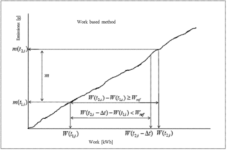
The duration (t 2,i – t 1,i ) of the ith averaging window is determined by:

where:
W(tj,i ) is the engine work measured between the start and time tj,i , kWh;
Wref is the engine work for the WHTC, kWh;
t 2,i shall be selected such that:

Where Δt is the data sampling period, equal to 1 second or less.
4.2.1. Calculation of the specific emissions U.K.
The specific emissions e gas (mg/kWh) shall be calculated for each window and each pollutant in the following way:

where:
m is the mass emission of the component, mg/window
W(t2,i) – W(t1,i) is the engine work during the ith averaging window, kWh
[F54.2.1.1. Calculation of the specific emissions for a declared market fuel U.K.
If a test pursuant to this Annex was performed with a market fuel declared in point 3.2.2.2.1 of Part 1 in Appendix 4 to Annex I, the specific emissions e gas (mg/kWh) shall be calculated for each window and each pollutant by multiplication of the uncorrected specific emissions with the power correction factor determined pursuant to point 1.1.2 (a1) of Annex I.]
Textual Amendments
[F24.2.2. Selection of valid windows U.K.
4.2.2.1. Before the dates referred to in Article 17a, points 4.2.2.1.1 to 4.2.2.1.4 shall apply. U.K.
4.2.2.1.1. The valid windows are the windows whose average power exceeds the power threshold of 20 % of the maximum engine power. The percentage of valid windows shall be equal or greater than 50 %. U.K.
4.2.2.1.2. If the percentage of valid windows is less than 50 %, the data evaluation shall be repeated using lower power thresholds. The power threshold shall be reduced in steps of 1 % until the percentage of valid windows is equal to or greater than 50 %. U.K.
4.2.2.1.3. In any case, the lower threshold shall not be lower than 15 %. U.K.
4.2.2.1.4. The test shall be void if the percentage of valid windows is less than 50 % at a power threshold of 15 %. U.K.
4.2.2.2. From the dates referred to in Article 17a, points 4.2.2.2.1 and 4.2.2.2.2 shall apply. U.K.
4.2.2.2.1. The valid windows are the windows whose average power exceeds the power threshold of 10 % of the maximum engine power. U.K.
[F64.2.2.2.2. The test shall be void if the percentage of valid windows is less than 50 % or if there are no valid windows in respect of nitrogen oxides (NO x ) left in urban only operations after the 90 percentile rule has been applied.] ] U.K.
Textual Amendments
4.2.3. Calculation of the conformity factors U.K.
The conformity factors shall be calculated for each individual valid window and each individual pollutant in the following way:

where:
e is the brake-specific emission of the component, mg/kWh;
L is the applicable limit, mg/kWh.
4.3. CO2 mass based method U.K.

The duration (t2,i – t1,i ) of the ith averaging window is determined by:

where:
m CO2(tj,i ) is the CO2 mass measured between the test start and time tj,i , kg;
m CO2,ref is the CO2 mass determined for the WHTC, kg;
t 2,i shall be selected such as:

Where Δt is the data sampling period, equal to 1 second or less.
The CO2 masses are calculated in the windows by integrating the instantaneous emissions calculated according to the requirements introduced in point 3.5.
[F24.3.1. Selection of valid windows U.K.
4.3.1.1. Before the dates referred to in Article 17a, points 4.3.1.1.1 to 4.3.1.1.4 shall apply. U.K.
4.3.1.1.1. The valid windows shall be the windows whose duration does not exceed the maximum duration calculated from: U.K.
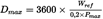
where:
D max is the maximum window duration, s,
P max is the maximum engine power, kW.
4.3.1.1.2. If the percentage of valid windows is less than 50 %, the data evaluation shall be repeated using longer window durations. This is achieved by decreasing the value of 0,2 in the formula given in point 4.3.1 by steps of 0,01 until the percentage of valid windows is equal to or greater than 50 %. U.K.
4.3.1.1.3. In any case, the lowered value in above formula shall not be lower than 0,15. U.K.
4.3.1.1.4. The test shall be void if the percentage of valid windows is less than 50 % at a maximum window duration calculated in accordance with points 4.3.1.1, 4.3.1.1.2 and 4.3.1.1.3. U.K.
4.3.1.2. From the dates referred to in Article 17a, points 4.3.1.2.1 and 4.3.1.2.2 shall apply. U.K.
4.3.1.2.1. The valid windows shall be the windows whose duration does not exceed the maximum duration calculated from: U.K.

where:
D max is the maximum window duration, s,
P max is the maximum engine power, kW.
4.3.1.2.2. The test shall be void if the percentage of valid windows is less than 50 %.] U.K.
4.3.2. Calculation of the conformity factors U.K.
The conformity factors shall be calculated for each individual window and each individual pollutant in the following way:

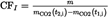

where:
m is the mass emission of the component, mg/window;
m CO2(t 2,i ) – m CO2(t 1,i ) is the CO2 mass during the ith averaging window, kg;
m CO2,ref is the engine CO2 mass determined for the WHTC, kg;
mL is the mass emission of the component corresponding to the applicable limit on the WHTC, mg.
Options/Help
Print Options
PrintThe Whole Regulation
PrintThe Whole Annex
PrintThis Division only
You have chosen to open the Whole Regulation
The Whole Regulation you have selected contains over 200 provisions and might take some time to download. You may also experience some issues with your browser, such as an alert box that a script is taking a long time to run.
Would you like to continue?
You have chosen to open Schedules only
The Schedules you have selected contains over 200 provisions and might take some time to download. You may also experience some issues with your browser, such as an alert box that a script is taking a long time to run.
Would you like to continue?
Legislation is available in different versions:
Latest Available (revised):The latest available updated version of the legislation incorporating changes made by subsequent legislation and applied by our editorial team. Changes we have not yet applied to the text, can be found in the ‘Changes to Legislation’ area.
Original (As adopted by EU): The original version of the legislation as it stood when it was first adopted in the EU. No changes have been applied to the text.
See additional information alongside the content
Geographical Extent: Indicates the geographical area that this provision applies to. For further information see ‘Frequently Asked Questions’.
Show Timeline of Changes: See how this legislation has or could change over time. Turning this feature on will show extra navigation options to go to these specific points in time. Return to the latest available version by using the controls above in the What Version box.
Opening Options
Different options to open legislation in order to view more content on screen at once
More Resources
Access essential accompanying documents and information for this legislation item from this tab. Dependent on the legislation item being viewed this may include:
- the original print PDF of the as adopted version that was used for the EU Official Journal
- lists of changes made by and/or affecting this legislation item
- all formats of all associated documents
- correction slips
- links to related legislation and further information resources
Timeline of Changes
This timeline shows the different versions taken from EUR-Lex before exit day and during the implementation period as well as any subsequent versions created after the implementation period as a result of changes made by UK legislation.
The dates for the EU versions are taken from the document dates on EUR-Lex and may not always coincide with when the changes came into force for the document.
For any versions created after the implementation period as a result of changes made by UK legislation the date will coincide with the earliest date on which the change (e.g an insertion, a repeal or a substitution) that was applied came into force. For further information see our guide to revised legislation on Understanding Legislation.
More Resources
Use this menu to access essential accompanying documents and information for this legislation item. Dependent on the legislation item being viewed this may include:
- the original print PDF of the as adopted version that was used for the print copy
- correction slips
Click 'View More' or select 'More Resources' tab for additional information including:
- lists of changes made by and/or affecting this legislation item
- confers power and blanket amendment details
- all formats of all associated documents
- links to related legislation and further information resources
 All content is available under the Open Government Licence v3.0 except where otherwise stated. This site additionally contains content derived from EUR-Lex, reused under the terms of the Commission Decision 2011/833/EU on the reuse of documents from the EU institutions. For more information see the EUR-Lex public statement on re-use.