SCHEDULE 14Signs for traffic control by light signals, signs for crossings, and signs for lane control
PART 2Light signals, signs and road markings for the control of traffic
(1) Item | (2) Description | (3) Diagram | (4) Variants | (5) Applicable requirement in Part 4 | (6) Schedule 14 General Directions |
|---|---|---|---|---|---|
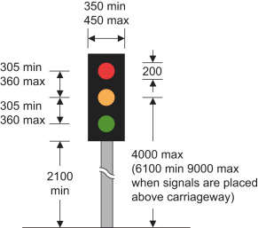
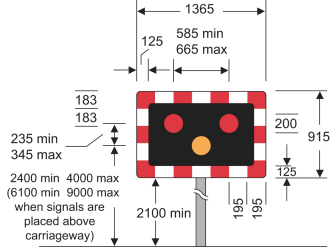
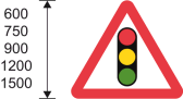
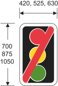
1 | Diagram 3000 Traffic light signals for the control of vehicular traffic at road junctions, places where the headroom or the width of the road is permanently restricted, signal controlled crossing facilities, tunnels, or in conjunction with the road marking provided for at item 15 of the table in part 6 of schedule 9 | Where the layout or character of the road restricts the visibility of the signals shown in the diagram, the maximum height of 4000 mm may be increased as appropriate to a maximum of 6100 mm | 1, 2, 3 | 2, 3, 4, 5, 43, 46 | |
2 | Diagram 3000.1 Portable traffic light signals for the control of vehicular traffic | 1, 2, 3 | 5, 6, 42, 43 | ||
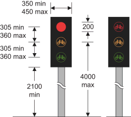
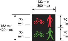
3 | Diagram 3000.2 Traffic light signals for the control of vehicular traffic consisting solely of pedal cycles (Alternative types) | 1, 2, 3 | 2, 3, 5, 43, 46 | ||
4 | Diagram 3000.2A Traffic light signals for the control of vehicular traffic consisting solely of pedal cycles (Alternative types) | 1, 2 | 2, 3, 5, 43, 46 | ||
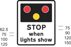
5 | Diagram 3014 Light signals for the control of road traffic at level crossings, swing or lifting bridges, airfields or in the vicinity of premises used regularly by fire and rescue authority, Scottish Fire and Rescue Service, police or ambulance vehicles | 1, 2, 3 | 2, 4, 5, 46 | ||
6 | Diagram 773 The light signals provided for at item 5 are ahead (where those light signals are at level crossing, swing or lifting bridge, or airfields) | 1. A distance may be added 2. An arrow pointing horizontally to the left or to the right may be added | 7 | ||
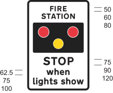
7 | Diagram 563.1 The light signals provided for at item 5 are ahead (where those light signals are in the vicinity of premises used regularly by fire and rescue authority, Scottish Fire and Rescue Service, police or ambulance vehicles) | 1. “FIRE” may be varied to: (a) “AMBULANCE”; (b) “POLICE”; (c) “FIRE AND AMBULANCE”; (d) “FIRE AND POLICE”; (e) “POLICE AND AMBULANCE”; or (f) “FIRE, POLICE AND AMBULANCE” 2. A distance may be added 3. An arrow pointing horizontally to the left or to the right may be added | 8 | ||
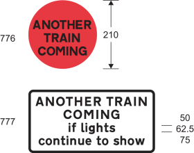
8 | Diagrams 776 and 777 Another train or tramcar may be about to pass over the crossing. Level crossing ahead is crossed by more than one railway or tramway track, and more than one train or tramcar may pass over it in quick succession | “TRAIN” may be varied to “TRAM” | 14 (in respect of the sign shown by the diagram numbered 776 only) | 9 | |
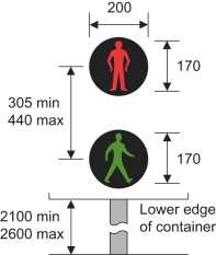
9 | Diagram 4002.1 Farside light signals for pedestrians | 3 | 3, 5, 10, 41, 42, 43, 46 | ||
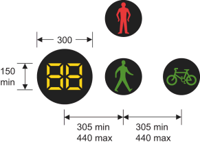
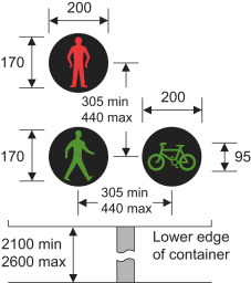
10 | Diagram 4002.1A Pedestrian countdown unit indicating to pedestrians the time remaining to cross the road (shown in combination with the signal provided for at item 19) | 1. Numerals may be varied 2. The positions of the countdown unit and green cycle aspect may be reversed 3. The cycle aspect may be omitted | 3, 5, 10, 42, 43 | ||
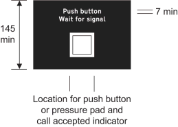
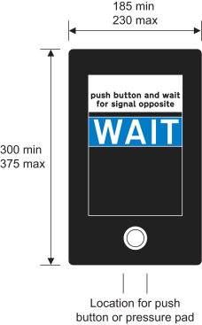
11 | Diagram 4003 Instructions to pedestrians above the push button control for calling up pedestrian phases at traffic light signals | The legend ‘WAIT’ may be illuminated in white or yellow | 3, 5, 11 ,42, 43, 46 | ||
12 | Diagram 4003.8 Instructions to road users for calling up pedestrian, equestrian or cyclist phases at traffic light signals | 3, 12, 42, 43, 46 | |||
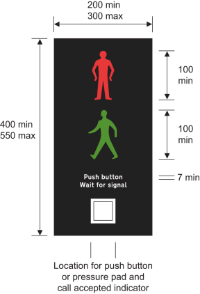
13 | Diagram 4003.1 Nearside light signals and instructions for pedestrians at a pedestrian facility controlled by traffic light signals | 1. The symbols may be reversed 2. The legend ‘stand on mat’ may be added between the legends ‘push button’ and ‘wait for signal’ 3. The horizontal positions of the red and green symbols may be varied independently of each other 4. Multiple red and green symbols may be provided 5. The face containing the signal and instructions may be curved and may comprise more than one unit | 3, 5, 13, 42, 43, 46 | ||
14 | Diagram 4003.1A Supplementary nearside light signals for pedestrians a pedestrian facility controlled by traffic light signals | 1. The symbols may be reversed 2. The horizontal positions of the red and green symbols may be varied independently of each other 3. The face containing the signal may be curved | 3, 5, 14, 43, 46 | ||
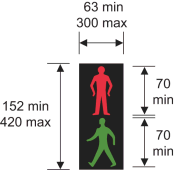
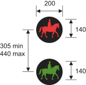
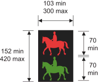
15 | Diagram 4003.2 Farside light signals for equestrian traffic | The symbols may be reversed | 3 | 3, 5, 15, 41, 43, 46 | |
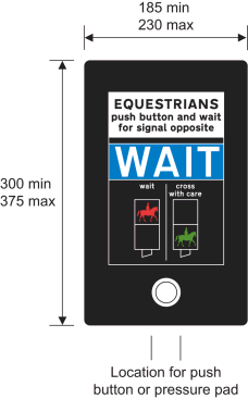
16 | Diagram 4003.3 Instructions to horse riders above the push button control for calling up equestrian traffic phases at traffic light signals | The legend ‘WAIT’ may be illuminated in white or yellow | 3, 5, 16, 43, 46 | ||
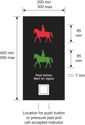
17 | Diagram 4003.4 Nearside light signals and instructions for horse riders at an equestrian traffic crossing facility controlled by traffic light signals | 1. The symbols may be reversed 2. The horizontal positions of the red and green ridden horse symbols may be varied independently of each other 3. Multiple red and green ridden horse symbols may be provided. 4. The face containing the signal and instructions may be curved and may comprise more than one unit | 3, 5, 17, 41, 43, 46 | ||
18 | Diagram 4003.4A Supplementary nearside light signals for horse riders at an equestrian traffic crossing facility controlled by traffic light signals | 1. The symbols may be reversed where appropriate 2. The horizontal positions of the red and green ridden horse symbols may be varied independently of each other 3. The face containing the signal may be curved | 3, 5, 18, 43, 46 | ||
19 | Diagram 4003.5 Farside light signals for pedestrians and cyclists at a Toucan crossing | The cycle aspect may be positioned to the left of the green pedestrian aspect | 3 | 3, 5, 19, 41, 43, 46 | |
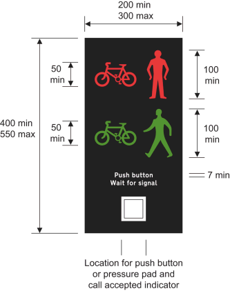
20 | Diagram 4003.6 (a) instructions to pedestrians and cyclists above the push button control for calling up pedestrian and cycle phases at a Toucan crossing; or (b) instructions to cyclists above the push button control for calling up cycle phases at a crossing controlled by the traffic light signals provided for at item 3 or 4 | The legend ‘WAIT’ may be illuminated in white or yellow | 3, 5, 20, 43, 46 | ||
21 | Diagram 4003.7 Nearside light signals and instructions for pedestrians and cyclists at a Toucan crossing | 1. The combined cycle and pedestrian symbols may be reversed in a mirror image 2. The face containing the signal and instructions may be curved and may comprise more than one unit | 3, 5, 21, 41, 43, 46 | ||
22 | Diagram 4003.7A Supplementary nearside signals for pedestrians and cyclists at a Toucan crossing | 1. The combined cycle and pedestrian symbols may be reversed in a mirror image 2. The face containing the signal may be curved | 3, 5, 22, 43, 46 | ||
23 | Diagram 4004 Signals placed at or near a school crossing place where children likely to be crossing the road on their way to or from school ahead (Alternative types) | The container may be coloured grey | 5, 23 | ||
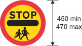
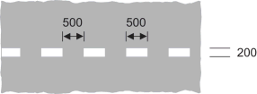
24 | Diagram 605.3 School crossing patrol sign | 1, 2, 12 | |||
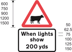
25 | Diagram 4005 A cattle crossing lies ahead and may be in use | 3 | 5, 24 | ||
26 | Diagram 4006 Light signal at level crossing for pedestrians conveying the prohibition that pedestrians must not proceed beyond the marking provided for at item 68 | 3 | 5, 25, 46 | ||
27 | Diagram 4007 Yellow or fluorescent yellow globe to indicate presence of a Parallel, or Zebra crossing | 13 | |||
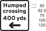
28 | Diagram 543 Traffic signals ahead | ||||
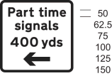
29 | Diagram 543.1 Traffic signals in the direction indicated which only operate at certain times (Supplementary plate) | 1. “Part time signals” may be varied to “Peak hour signals” or “Traffic control” or omitted 2. The sign may show a different distance or the distance may be omitted 3. The arrow may be reversed to point horizontally to the right or omitted 4. When “Part time signals” is omitted, the x-height of the legend may be varied to 200 mm | 26 | ||
30 | Diagram 544 Zebra crossing or Parallel crossing ahead | ||||
31 | Diagram 547.8 Zebra crossing, Parallel crossing, or signal‑controlled crossing on a road hump, in the direction indicated (Supplementary plate) | 1. “Humped crossing” may be varied to “Zebra crossing” or “Parallel crossing” or omitted 2. The sign may show a different distance or the distance may be omitted 3. The arrow may be reversed to point horizontally to the right or omitted 4. When “Humped crossing” is omitted, the x-height of the legend may be varied to 150 mm or 200 mm | 27 | ||
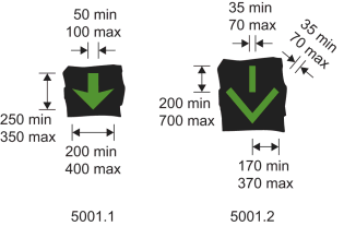
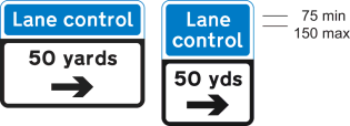
32 | Diagrams 5001.1 and 5001.2 Lane open to vehicular traffic (Alternative types) | 5, 28, 46 | |||
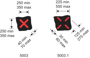
33 | Diagrams 5003 and 5003.1 Lane closed to vehicular traffic (Alternative types) | 5, 28, 46 | |||
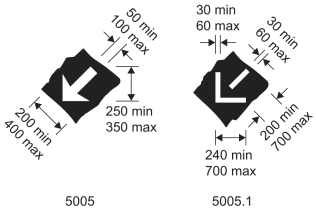
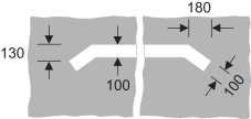
34 | Diagrams 5005 and 5005.1 Lane closed ahead and vehicular traffic should move to the next lane on the left (Alternative types) | 5, 28, 46 | |||
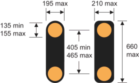
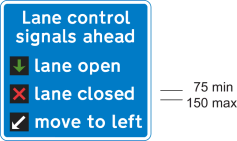
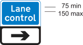
35 | Diagram 5010 The lane control light signals provided for at items 32, 33 and 34 ahead | The diagonal white arrow symbol and the words ‘move to left’ may be omitted where the signals provided for at item 34 are not used in the lane control system | 8 | ||
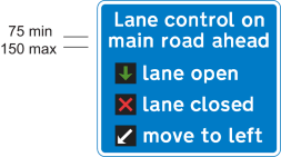
36 | Diagram 5011 The lane control light signals provided for at items 32, 33 and 34 ahead on a road extending from a junction | The diagonal white arrow symbol and the words ‘move to left’ may be omitted where the signals provided for at item 34 are not used in the lane control system | 8 | ||
37 | Diagram 5012 System of lane control light signals ahead | ||||
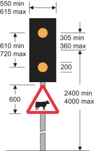
38 | Diagram 5013 Direction of a system of lane control light signals | The direction of the arrow may be varied with the arrow or chevron pointing horizontally to the left | |||
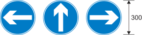
39 | Diagram 5014 Distance to and direction of a system of lane control light signals (alternative types) | 1. The sign may show a different distance 2. The arrow may point horizontally to the left or may be omitted | |||
40 | Diagram 5015 End of a system of lane control light signals | ||||
41 | Diagram 548.1A Supervised cattle crossing ahead | 1. The sign shown in the lower part of the diagram may show a different distance 2. An arrow pointing to the left or to the right may be added to the sign shown in the lower part of the diagram | |||
42 | Diagram 606 Vehicular traffic may proceed only in the direction indicated by the arrow (Alternative types) | The diameter may be not less than 95 mm and not more than 110 mm if the sign is placed in conjunction with the sign provided for at item 4 | 10 | 28, 29 | |
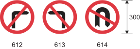
43 | Diagrams 612, 613 and 614 No right, left, or u-turn for vehicular traffic (Alternative types) | The diameter may be not less than 95 mm and not more than 110 mm if the sign is placed in conjunction with the sign provided for at item 4 | 10 | 28, 29 | |
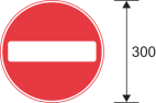
44 | Diagram 616 No entry for vehicular traffic | 10 | 28, 30 | ||
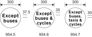
45 | Diagrams 954.5, 954.6 and 954.7 Classes of vehicle excluded from restriction or prohibition conveyed by associated sign (Alternative types) | The legend may be varied to “Except” and “cycles”, “local buses”, “buses & taxis”, local buses & cycles” or “local buses & taxis” | 10 | 28 | |
46 | Diagram 1001 Vehicular traffic must not proceed beyond the line when required to stop by light signals, by a constable in uniform or by a traffic warden | 4, 5 | 31, 42, 43 | ||
47 | Diagram 1001.1 Tramcars must not proceed beyond the line when required to stop by light signals | 4 | 32 | ||
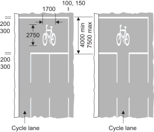
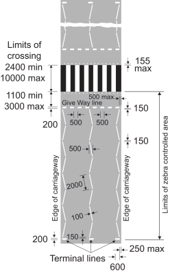
48 | Diagram 1001.2 Alternatives to the stop line provided for at item 46 showing separate stop lines for pedal cycles proceeding in the cycle lane | 1. The number of traffic lanes may be varied 2. The nearside cycle lane may be bounded by the continuous white line provided for at item 7 of the sign table in Part 6 of Schedule 9 3. The right hand longitudinal line may be omitted where that part of the carriageway is delineated by a raised kerb | 4, 5 | 33 | |
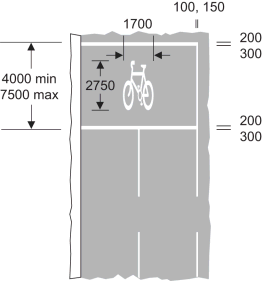
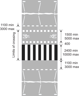
49 | Diagram 1001.2B Alternative to the stop line provided for at item 46 showing separate stop lines for pedal cycles. | 1. The number of traffic lanes may be varied 2. The right hand longitudinal line may be omitted where that part of the carriageway is delineated by a raised kerb | 4, 5 | 33 | |
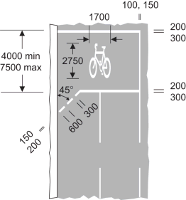
50 | Diagram 1001.2A Alternatives to the stop line provided for at item 46 showing a separate stop line at a junction for pedal cycles proceeding through the cycle entry | 1. The number of traffic lanes may be varied 2. The right hand longitudinal line may be omitted where that part of the carriageway is delineated by a raised kerb 3. The number of marks in the diagonal line may be varied | 4, 5 | 33 | |
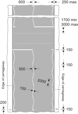
51 | Diagram 1001.3 Zig-zag lines to indicate requirements or prohibitions relating to stopping or overtaking at a Puffin crossing, signal-controlled crossing facility or portable signal-controlled pedestrian facility (shown in combination with the markings provided for at items 46 and 55) | 1. Subject to entry 4, each zig-zag line may contain more than 8 marks but not more than 18 marks 2. The central zig-zag line may be reversed, or where the road is not more than 6 metres wide, may be omitted 3. Each zig-zag line need not contain the same number of marks as any other line, provided each mark is of the same length as the others 4. Where the traffic authority is satisfied that the layout or character of the road means it is not practical to lay 8 marks, the number of marks can be reduced to not less than 2 5. Where there is a central refuge or reservation in the carriageway the zig-zag lines may be marked on each side of the refuge or reservation provided that the markings on each side are indicated as separate crossings 6. Where a central refuge or reservation is provided, the markings provided for at item 23 of Part 4 of Schedule 11 (and shown in the second diagram of that item) may be placed between the zig-zag lines on the approaches 7.The zig-zag lines may to be placed up to 2 metres from the edge of the carriageway to allow cyclists to ride on the nearside of the lines | 1, 2, 5 | 34, 42, 43 | |
52 | Diagram 1001.4: Zig-zag lines to indicate the requirements or prohibitions relating to stopping or overtaking at a Zebra crossing (shown in combination with the marking provided for at item 54, the stripes provided for at paragraph 18 of Part 1 and the marking provided for at item 55) | 1. Subject to entry 4, each zig-zag line may contain more than 8 marks but not more than 18 marks 2. The central zig-zag line may be reversed, or where the road is not more than 6 metres wide, may be omitted 3. Each zig-zag line need not contain the same number of marks as any other line, provided each mark is of the same length as the others 4. Where the traffic authority is satisfied that the layout or character of the road means it is not practical to lay 8 marks, the number of marks can be reduced to not less than 2 5. Where there is a central refuge or reservation in the carriageway the zig-zag lines may be marked on each side of the refuge or reservation, as the case may be, provided that the marking on each side are indicated as separate crossings 6. Where a central refuge or reservation is provided, the markings provided for at item 23 of the table in Part 4 of Schedule 11 and shown in the bottom diagram at that item (vehicular traffic not to enter part of the carriageway) may be placed between the zig-zag lines on the approaches. 7.The zig-zag lines may to be placed up to 2 metres from the edge of the carriageway to allow cyclists to ride on the nearside of the lines 8. The marking provided for at item 55 may be omitted 9. The maximum distance of 3 metres between the give-way line and the limits of the crossing may, if the traffic authority thinks fit, be increased to not more than 10 metres | 1, 2 | ||
53 | 1001.5 Zig-zag lines to indicate the requirements or prohibitions relating to stopping or overtaking at a Parallel pedestrian and cyclist crossing (shown in combination with markings provided for at items 54 and 57 and the stripes provided for at paragraph 18 of Part 1) | 1. Subject to entry 4, each zig-zag line may contain more than 8 marks but not more than 18 marks. 2. The central zig-zag line may be reversed, or where the road is not more than 6 metres wide, may be omitted 3. Each zig-zag line need not contain the same number of marks as any other line, provided each mark is of the same length as the others 4. Where the traffic authority is satisfied that the layout or character of the road means it is not practical to lay 8 marks, the number of marks can be reduced to not less than 2 5. Where there is a central refuge or reservation in the carriageway the zig-zag lines may be marked on each side of the refuge or reservation, as the case may be, provided that the marking on each side are indicated as separate crossings 6. Where a central refuge or reservation is provided, the markings provided for at item 23 of the table in Part 4 of Schedule 11 and shown in the bottom diagram at that item (vehicular traffic not to enter part of the carriageway) may be placed between the zig-zag lines on the approaches 7. The zig-zag lines may to be placed up to 2 metres from the edge of the carriageway to allow cyclists to ride on the nearside of the lines 8. The cycle symbols may be omitted or reversed as appropriate | 1, 2 | ||
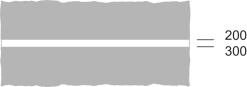
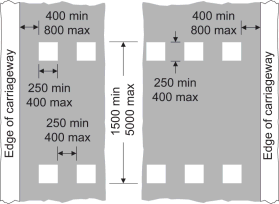
54 | Diagram 1001.5 Give-way marking for use at Zebra crossings, and Parallel pedestrian and cyclist crossings | ||||
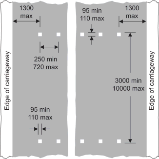
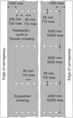
55 | Diagram 1055.1 (a) a place suitable for pedestrians to cross a road at which traffic is subject to control by a constable in uniform or by a traffic warden, being control which is normally in operation during periods amounting in aggregate to not less than 20 hours in any week; (b) the most suitable place for pedestrians to cross a carriageway within 10 metres of the traffic signals provided for at item 1; (c) place suitable for cyclists to cross a road at which cyclists are controlled by traffic light signals of the kind provided for at item 3 or 4, and other vehicular traffic is controlled by traffic signals of the kind provided for at item 1; (d) place suitable for pedestrians to cross at a signal (including portable) controlled pedestrian facility; (e) place suitable for pedestrians and cyclists to cross at a Toucan crossing; (f) place suitable for crossing at an equestrian only crossing; or (h) place suitable for pedestrians to cross forming part of a Zebra crossing | 1. The square marks may be varied to circular marks with a diameter between 95 mm and 110 mm 2. The square marks, or the circular marks referred to at 1, may be varied to square or circular non-depressible studs of the same size and shape which are coloured white, silver or light grey provided the studs are not fitted with reflectors, retroreflecting material or a light source 3. The number of marks may be varied according to the width of the road 4. The minimum width of the crossing, other than a Toucan crossing, may be reduced from 3000 mm to 2400 mm | 42, 43 | ||
56 | Diagram 1055.2 As for the description in this column of item 55, paragraph (c) (d) or (e), with an additional crossing point for equestrians | 1. The square marks may be varied to circular marks with a diameter between 95 mm and 110 mm 2. The square marks, or the circular marks referred to at 1, may be varied to square or circular non-depressible studs of the same size and shape which are coloured white, silver or light grey provided the studs are not fitted with reflectors, retroreflecting material or a light source 3. The number of marks may be varied according to the width of the road 4. The minimum width of the crossing, not being a Toucan crossing, may be reduced from 3000 mm to 2400 mm | 43 | ||
57 | Diagram 1055.3 (a) route for vehicular traffic consisting solely of pedal cyclists across a signal controlled junction (b) route for vehicular traffic consisting solely of pedal cyclists across a Parallel crossing | The marking may be varied to include the symbol shown in the diagram at item 28 of the sign table in Part 4 Schedule 11 (cycle symbol) | 35 | ||
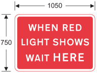
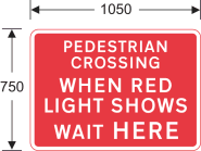
58 | Diagram 7011 Point beyond which vehicular traffic must not proceed when required to stop (in accordance with the provisions of Part 1) at portable light signals provided for at item 2 when the road marking provided for at item 46 is not placed on the carriageway | The legend may be varied as follows— (a) “WHEN STOP SIGN SHOWS WAIT HERE”; (b) “WHEN RED LIGHT SHOWS WAIT HERE FOR CONVOY VEHICLE”; (c) “WHEN STOP SIGN SHOWS WAIT HERE FOR CONVOY VEHICLE”; (d) “WHEN GREEN LIGHT SHOWS FOLLOW CONVOY VEHICLE”; or (e) “AT TRAFFIC CONTROL FOLLOW CONVOY VEHICLE” | 8 | ||
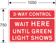
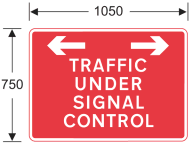
59 | Diagram 7011.1 As for item 58 where there is a road junction | ‘3-WAY’ may be varied to ‘4-WAY’ | 8 | ||
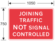
60 | Diagram 7011.2 Instruction to vehicular traffic at a portable signal-controlled pedestrian facility | 8 | 42, 43 | ||
61 | Diagram 7019 Traffic light signals not in use | ||||
62 | Diagram 7021 Traffic on road ahead is being controlled by portable light signals (indication to traffic joining that road) | 8 | |||
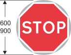
63 | Diagram 7022 Traffic joining a length of road being controlled by portable light signals is not controlled by such signals | ||||
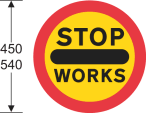
64 | Diagram 7023 Vehicular traffic must not proceed into a length of road where one-way working is temporarily necessary (manually operated sign) | 1, 6, 9 | 36 | ||
65 | Diagram 7024 Vehicular traffic may proceed into a length of road where one-way working is temporarily necessary (manually operated sign) | 6, 9 | 36 | ||
66 | Diagram 7031 Vehicular traffic must not proceed beyond the sign when displayed for a short period during works on or near an all‑purpose road (Double sided sign) | A red or transparent protective strip, with a visible width not exceeding 6 mm, may be applied to the perimeter of the sign | 1, 7, 11 | 37, 38 | |
67 | Diagram 790 New method of controlling traffic at a railway or tramway level crossing ahead – temporary sign | “CONTROL” may be omitted | 39 | ||
68 | Diagram 1003.2 Pedestrians approaching a level crossing must wait behind the line when the barriers are closed or when the red figure in the sign provided for at item 26 or the light signals provided for at item 5 are showing or, if there are neither barriers nor light signals, until satisfied that it is safe to proceed | ||||
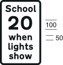
69 | Diagram 545.1 Part-time advisory 20 mph speed limit at or near a school | 40 |