SCHEDULES
SCHEDULE 4RULES OF THE AIR
SECTION 8LIGHTS AND OTHER SIGNALS TO BE SHOWN OR MADE BY AIRCRAFT
General
46.—(1) For the purposes of this Section of the Rules the horizontal plane of a light shown by an aircraft means the plane which would be the horizontal plane passing through the source of that light if the aircraft were in level flight.
(2) If it is necessary to fit more than one lamp in order to show a light required by this Section because of the physical construction of an aircraft, the lamps must be so fitted and constructed that, so far as is reasonably practicable, not more than one such lamp is visible from any one point outside the aircraft.
(3) If a light is required by this Section to show through specified angles in the horizontal plane, the lamps giving such light must be so constructed and fitted that the light is visible—
(a)from any point in any vertical plane within those angles throughout angles of 90° above and below the horizontal plane; but
(b)so far as is reasonably practicable, through no greater angle, either in the horizontal plane or the vertical plane.
(4) If a light is required by this Section to show in all directions, the lamps giving such light must be so constructed and fitted that, so far as is reasonably practicable, the light is visible from any point in the horizontal plane and on any vertical plane passing through the source of that light.
(5) Notwithstanding the provisions of this Section the pilot-in-command of an aircraft may switch off or reduce the intensity of any flashing light fitted to the aircraft if such a light does or is likely to—
(a)adversely affect the performance of the duties of any member of the flight crew; or
(b)subject an outside observer to unreasonable dazzle.
Display of lights by aircraft
47.—(1) During the night an aircraft must—
(a)display such of the lights specified in this Section as it is required by this Section; and
(b)subject to rule 49(6), not display any other lights which might obscure or otherwise impair the visibility of, or be mistaken for, such lights.
(2) Subject to rule 48(4) an aircraft fitted with an anti-collision light must display that light in flight during the day.
(3) A flying machine on a Territory aerodrome must—
(a)during the night display either the lights which it would be required to display when flying or the lights specified in rule 49(5)(c), unless it is stationary on the apron or on that part of the aerodrome provided for the maintenance of aircraft; and
(b)during the day and night and subject to paragraph (4), display a red anti-collision light, if it is fitted with one, when it is stationary on the apron with engines running.
(4) A helicopter to which article 96 applies may, when stationary on an offshore installation, switch off the anti-collision light required to be shown by paragraph (3)(b) as long as that is done in accordance with a procedure contained in the operations manual of the helicopter as a signal to ground personnel that it is safe to approach the helicopter for the purpose of embarkation or disembarkation of passengers or the loading or unloading of cargo.
Failure of navigation and anti-collision lights
48.—(1) Paragraphs (2), (3) and (4) apply to aircraft in the Territory.
(2) An aircraft must not depart from an aerodrome if there is a failure of any light which these Rules require to be displayed at night and the light cannot be immediately repaired or replaced.
(3) Subject to paragraph (4), if the aircraft is in flight and any such light as is referred to in paragraph (2) fails and cannot be immediately repaired or replaced, the aircraft must land as soon as it can safely do so, unless authorised by the appropriate air traffic control unit to continue its flight.
(4) An aircraft may continue to fly during the day in the event of a failure of an anti-collision light on the flight as long as the light is repaired at the earliest practicable opportunity.
Flying machines at night
49.—(1) Subject to paragraph (6), a flying machine flying at night must display lights in accordance with paragraphs (2), (3) or (4), as appropriate.
(2) In the case of—
(a)a flying machine registered in the Territory which has a maximum total weight authorised of more than 5,700 kg; or
(b)any other flying machine registered in the Territory which conforms to a type first issued with a type certificate on or after 1st April 1988,
the flying machine must display the system of lights specified in paragraph 5(b).
(3) A flying machine registered in the Territory which—
(a)conforms to a type first issued with a type certificate before 1st April 1988; and
(b)has a maximum total weight authorised of 5,700 kg or less,
must display the system of lights specified in—
(i)paragraph (5)(a); or
(ii)paragraph (5)(b); or
(iii)paragraph (5)(d), but excluding sub-paragraph (ii) of that paragraph.
(4) In the case of any other flying machine, one of the systems of lights specified in paragraph (5) must be displayed.
(5) The systems of lights referred to in paragraphs (2), (3) and (4) are as follows—
(a)A steady green light of at least five candela showing to the starboard side through an angle of 110° from dead ahead in the horizontal plane; a steady red light of at least five candela showing to the port side through an angle of 110° from dead ahead in the horizontal plane; and a steady white light of at least three candela showing through angles of 70° from dead astern to each side in the horizontal plane;
(b)the lights specified in sub-paragraph (a) and an anti-collision light;
(c)the lights specified in sub-paragraph (a), but all being flashing lights (rather than steady lights) flashing together;
(d)the lights specified in sub-paragraph (a), but all being flashing lights (rather than steady lights) flashing together in alternation with one or both of the following—
(i)a flashing white light of at least 20 candela showing in all directions;
(ii)a flashing red light of at least 20 candela showing through angles of 70° from dead astern to each side in the horizontal plane.
(6) If the lamp showing either the red or the green light specified in paragraph (5)(a) is fitted more than 2 metres from the wing tip, another lamp may be fitted at the wing tip to indicate its position showing a steady light of the same colour through the same angle.
Gliders at night
50. A glider flying at night must display either a steady red light of at least five candela, showing in all directions, or lights in accordance with rule 49(5) and (6).
Free balloons at night
51. A free balloon flying at night must display a steady red light of at least five candela showing in all directions, suspended not less than 5 metres and not more than 10 metres below the basket, or if there is no basket, below the lowest part of the balloon.
Captive balloons and kites at night
52.—(1) A captive balloon or kite flying at night at a height exceeding 60 metres above the surface must display lights in accordance with paragraphs (2), (3) and (4).
(2) A group of two steady lights must be displayed consisting of a white light placed 4 metres above a red light, both being of at least five candela and showing in all directions, the white light being placed not less than 5 metres nor more than 10 metres below the basket or, if there is no basket, below the lowest part of the balloon or kite.
(3) On the mooring cable of the balloon or kite, at intervals of not more than 300 metres measured from the group of lights specified in paragraph (2), there must be displayed—
(a)groups of two lights of the colour and power and in the relative positions specified in paragraph (2); and
(b)if the lowest group of lights is obscured by cloud, an additional group of such lights below the cloud base.
(4) On the surface of the ground there must be displayed a group of three flashing lights arranged—
(a)in a horizontal plane at the apexes of a triangle, approximately equilateral, each side of which measures at least 25 metres;
(b)so that one side of the triangle must be approximately at right angles to the horizontal projection of the cable and must be delimited by two red lights; and
(c)so that the third light must be a green light, placed so that the triangle encloses the object on the surface to which the balloon or kite is moored.
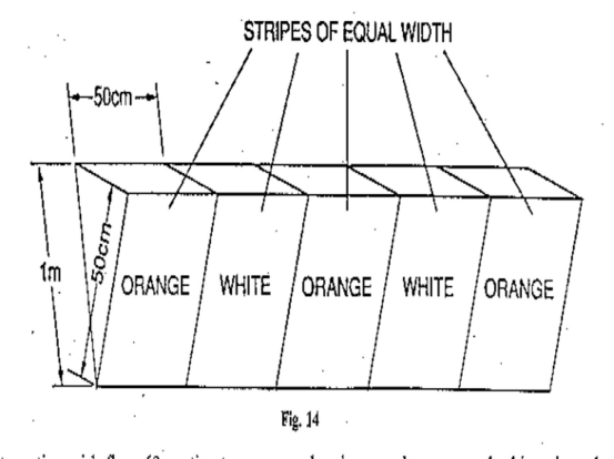
Captive balloons and kites by day
53.—(1) A captive balloon flying by day at a height exceeding 60 metres above the surface must have attached to its mooring cable tubular streamers which are—
(a)not less than 40 centimetres in diameter and 2 metres in length; and
(b)marked with alternate bands of red and white 50 centimetres wide at intervals of not more than 200 metres measured from the basket or, if there is no basket, from the lowest part of the balloon.
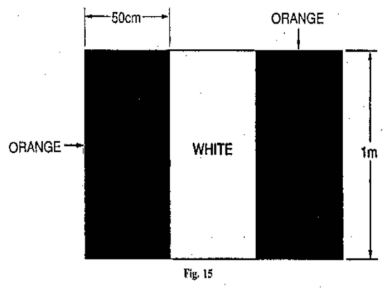
(2) A kite flying by day at a height exceeding 60 metres above the surface must have attached to its mooring cable either—
(a)tubular streamers as specified in paragraph (1); or
(b)at intervals of not more than 100 metres measured from the lowest part of the kite, streamers not less than 80 centimetres long and 30 centimetres wide at their widest point, marked with alternate bands of red and white 10 centimetres wide.
Airships at night
54.—(1) Except as provided in paragraph (2), an airship flying at night must display the following lights—
(a)a steady white light of at least five candela showing through angles of 110° from dead ahead to each side in the horizontal plane;
(b)a steady green light of at least five candela showing to the starboard side through an angle of 110° from dead ahead in the horizontal plane;
(c)a steady red light of at least five candela showing to the port side through an angle of 110° from dead ahead in the horizontal plane;
(d)a steady white light of at least five candela showing through angles of 70° from dead astern to each side in the horizontal plane; and
(e)an anti-collision light.
(2) Subject to paragraph (5), an airship flying at night in any of the circumstances referred to in paragraph (3) must display the lights specified in paragraph (4).
(3) The circumstances are as follows—
(a)if the airship is not under command; or
(b)has voluntarily stopped its engines, or
(c)is being towed.
(4) The lights specified are the following lights—
(a)the white lights specified in paragraph (1)(a) and (d);
(b)two steady, red lights, each of at least five candela, showing in all directions, suspended below the control car so that one is at least 4 metres above the other and at least 8 metres below the control car; and
(c)if the airship is making way but not otherwise, the green and red lights specified in paragraph (1)(b) and (c).
(5) An airship picking up its moorings at night must display the lights specified in paragraph (1).
(6) An airship moored to a mooring mast within the Territory at night must display, at or near the rear of the airship, a steady, white light of at least five candela showing in all directions.
(7) An airship moored otherwise than to a mooring mast within the Territory at night must display—
(a)a white light of at least five candela showing through angles of 110° from dead ahead to each side in the horizontal plane; and
(b)a white light of at least five candela showing through angles of 70° from dead astern to each side in the horizontal plane.
Airships by day
55.—(1) An airship flying during the day in any of the circumstances referred to in paragraph (2) must display two black balls suspended below the control car so that one is at least 4 metres above the other and at least 8 metres below the control car.
(2) The circumstances are as follows—
(a)if the airship is not under command;
(b)if it has voluntarily stopped its engines; or
(c)if it is being towed.
(3) For the purposes of this rule and rule 54—
(a)an airship is deemed not to be under command when it is unable to execute a manoeuvre which it may be required to execute by these Rules; and
(b)an airship is deemed to be making way when it is not moored and is in motion.
Signals in the Signals Area
56.—(1) Whenever any signal specified in this rule is displayed it shall be placed in a signals area, which shall be a square visible from all directions bordered by a white strip 30 centimetres wide and with the internal sides measuring 12 metres.
(2) A white landing T, as illustrated in this paragraph,

signifies that aeroplanes and gliders taking off or landing shall do so in a direction parallel with the shaft of the T and towards the cross arm, unless otherwise authorised by the appropriate air traffic control unit.
(3) A white disc 60 centimetres in diameter displayed alongside the cross arm of the T and in line with the shaft of the T, as illustrated in this paragraph,

signifies that the direction of landing and take off do not necessarily coincide.
(4) A white dumb-bell, as illustrated in this paragraph,

signifies that movements of aeroplanes and gliders on the ground shall be confined to paved, metalled or similar hard surfaces.
A white dumb-bell, as described in paragraph (4), but with a black strip 60 centimetres wide across each disc at right angles to the shaft of the dumb-bell, as illustrated in this paragraph,

signifies that aeroplanes and gliders taking off or landing shall do so on a runway but that movement on the ground is not confined to paved, metalled or similar hard surfaces.
(5) A red and yellow striped arrow, as illustrated in this paragraph,

the shaft of which is one metre wide and which is placed along the whole or a total of 11 metres of two adjacent sides of the signals area, and pointing in a clockwise direction, signifies that a right-hand circuit is in force.
(6) A red panel 3 metres square with a yellow strip along one diagonal 50 centimetres wide, as illustrated in this paragraph,

signifies that the state of the manoeuvring area is poor and pilots must exercise special care when landing.
(7) A red panel 3 metres square with a yellow strip 50 centimetres wide along each diagonal, as illustrated in this paragraph,

signifies that the aerodrome is unsafe for the movement of aircraft and that landing on the aerodrome is prohibited.
(8) A white letter H, as illustrated in this paragraph,

signifies that helicopters shall take off and land only within the area designated by the marking specified in rule 59(7).
(9) A red letter L displayed on the dumb-bell specified in paragraphs (4) and (5), as illustrated in this paragraph,

signifies that light aircraft are permitted to take off and land either on a runway or on the area designated by the marking specified in rule 59(8).
(10) A white double cross, as illustrated in this paragraph,

signifies that glider flying is in progress.
Markings for paved runways and taxiways
57.—(1) Two or more white crosses, as illustrated in this paragraph,
displayed on a runway or taxiway, with each arm of each cross at an angle of 45° to the centre line of the runway, at intervals of not more than 300 metres signify that the section of the runway or taxiway marked by them is unfit for the movement of aircraft.
(2) Subject to paragraph (3), two yellow broken lines and two continuous lines, as illustrated
in this paragraph, signify the designated visual holding position associated with a runway beyond which no part of a flying machine or vehicle shall project in the direction of the runway without permission from the air traffic control unit at the aerodrome during the notified hours of watch of that unit.
(3) Outside the notified hours of watch of that unit or where there is no air traffic control unit at the aerodrome the markings referred to in paragraph (2) signify the position closest to the runway beyond which no part of a flying machine or vehicle shall project in the direction of the runway when the flying machine or vehicle is required by virtue of rule 42(3) to give way to aircraft which are taking off from or landing on that runway.
Subject to paragraph (5), a yellow marking, as illustrated in this paragraph,
signifies a holding position other than that closest to the runway beyond which no part of a flying machine or vehicle shall project in the direction of the runway without permission from the air traffic control unit at the aerodrome during the notified hours of watch of that unit.
(4) Outside the notified hours of watch of that unit or where there is no air traffic control unit at the aerodrome the marking referred to in paragraph (4) may be disregarded.
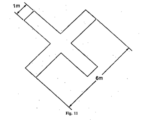
(5) Orange and white markers, as illustrated in this paragraph,
spaced no more than 15 metres apart, signify the boundary of that part of a paved runway, taxiway or apron which is unfit for the movement of aircraft.
Markings on unpaved manoeuvring areas
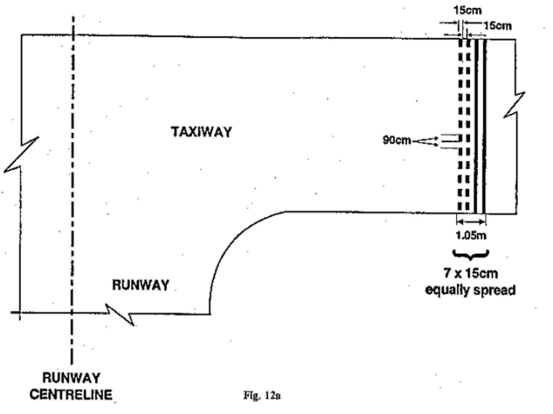
58.—(1) Markers with orange and white stripes of an equal width of 50 centimetres, with an orange stripe at each end, alternating with flags 60 centimetres square showing equal orange and white triangular areas, spaced not more than 90 metres apart as illustrated in this paragraph,
indicate the boundary of an area unfit for the movement of aircraft.
(2) One or more white crosses, as specified in rule 58(1), also indicate such an area as is referred to in paragraph (1).
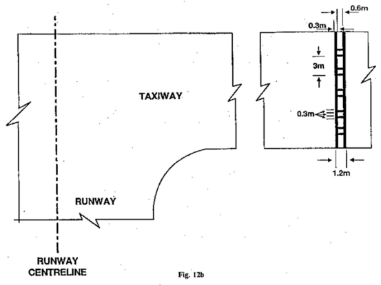
(3) Striped markers, as specified in paragraph (1), spaced not more than 45 metres apart, indicate the boundary of an aerodrome.
(4) On structures markers with orange and white vertical stripes, of an equal width of 50 centimetres, with an orange stripe at each end, spaced not more than 45 metres apart, as illustrated in this paragraph.
indicate the boundary of an aerodrome.
(5) The pattern of the marker referred to in paragraph (4) shall be visible from inside and outside the aerodrome and the marker shall be affixed not more than 15 centimetres from the top of the structure.
(6) White, flat, rectangular markers 3 metres long and 1 metre wide, at intervals not exceeding 90 metres, flush with the surface of an unpaved runway or stopway, indicate the boundary of the unpaved runway or stopway.
(7) A white letter H, as illustrated in this paragraph,
indicates an area which shall be used only for the taking off and landing of helicopters.
(8) A white letter L, as illustrated in this paragraph,

indicates a part of the manoeuvring area which shall be used only for the taking off and landing of light aircraft.
(9) A yellow cross with two arms each 6 metres long by 1 metre wide at right angles, indicates that tow ropes, banners and similar articles towed by aircraft shall only be picked up and dropped in the area in which the cross is placed.
(10) A white double cross, as illustrated in this paragraph,

indicates an area which shall be used only for the taking off and landing of gliders.
(11) Subject to paragraph (12) a white landing T, as specified in rule 57(2), placed at the left-hand side of the runway (when viewed from the direction of landing) indicates the runway to be used for take-off and landing.
(12) The white landing T referred to in paragraph (11), when placed at an aerodrome with no runway, indicates the direction for take-off and landing.
Signals visible from the ground
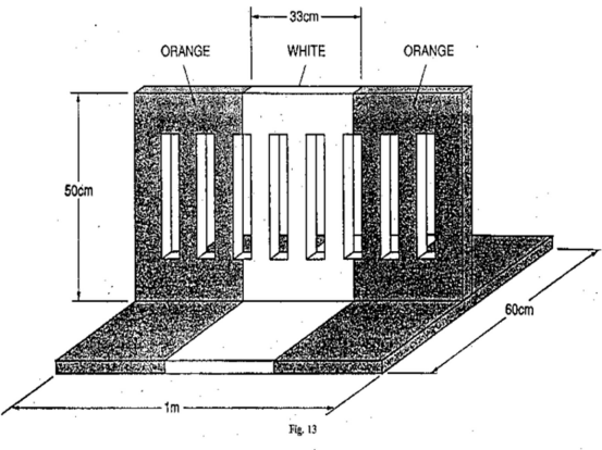
59.—(1) A black ball, 60 centimetres in diameter, suspended from a mast signifies that the directions of take-off and landing are not necessarily the same.
(2) A chequered flag or board, 1.2 metres by 90 centimetres, containing 12 equal squares, 4 horizontally and 3 vertically, coloured red and yellow alternately, signifies that aircraft may move on the manoeuvring area and apron only in accordance with the permission of the air traffic control unit at the aerodrome.
(3) Two red balls, 60 centimetres in diameter, positioned vertically one above the other, 60 centimetres apart and suspended from a mast, signify that glider flying is in progress at the aerodrome.
(4) Black, Arabic numerals in two-figure groups and, where parallel runways are provided, the letter or letters L (left), LC (left centre), C (centre), RC (right centre) and R (right), placed against a yellow background, indicate the direction for take-off or the runway in use.
(5) A black letter C against a yellow background, as illustrated in this paragraph,
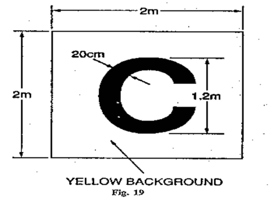
indicates the position at which a pilot can report to the air traffic control unit or to the person in charge of the aerodrome.
(6) A rectangular green flag of not less than 60 centimetres square and not more than 66 centimetres square, flown from a mast, indicates that a right-hand circuit is in force.
Lights and pyrotechnic signals for control of aerodrome traffic
60. Each signal described in column 1 of Table 4 shall have the meanings respectively appearing in columns 2, 3 and 4 of the Table in the circumstances specified in the second row of the Table.
Table 4—Meaning Of Lights And Pyrotechnic Signals
Column 1 | Column 2 | Column 3 | Column 4 |
|---|---|---|---|
Characteristic and colour of light beam or pyrotechnic | Directed from an aerodrome to an aircraft in flight | Directed from an aerodrome to an aircraft or vehicle on the aerodrome | Directed from an aircraft in flight to an aerodrome |
(a) Continuous red light. | Give way to other aircraft and continue circling. | Stop. | — |
| (b) Red pyrotechnic light, or red flare. | Do not land; wait for permission. | — | Immediate assistance is required. |
| (c) Red flashes. | Do not land; aerodrome not available for landing. | Move clear of landing area. | — |
| (d) Green flashes. | Return to aerodrome; wait for permission to land. | To an aircraft: you may move on the manoeuvring area and apron. To a vehicle: you may move on the manoeuvring area. | — |
| (e) Continuous green light. | You may land. | You may take off (not applicable to a vehicle). | — |
| (f) Continuous green light, or green flashes, or green pyrotechnic light. | — | — | By night: May I land? By day: May I land from direction different from that indicated by landing T? |
| (g) White flashes. | Land at the aerodrome after receiving continuous green light, and then, after receiving green flashes, proceed to the apron. | Return to starting point on the aerodrome. | I am compelled to land. |
(h) White pyrotechnic lights. Switching on and off the navigation lights. Switching on and off the landing lights. | — | — | I am compelled to land. |
Marshalling signals (from a marshaller to an aircraft)
61.—(1) Each of the signals for the guidance of aircraft manoeuvring on or off the ground, described in column 1 of Table 5 and as illustrated in column 3, when given by a marshaller to an aircraft, shall have the meanings specified in column 2 of the Table.
(2) By day any such signals shall be given by hand or by circular bats and by night shall be given by torches or by illuminated wands.
Table 5—Meaning of Marshalling Signals (from a marshaller to an aircraft)
Column 1 | Column 2 | Column 3 | |||
|---|---|---|---|---|---|
Description of Signal | Meaning of signal | Illustration of signal | |||
1. Raise right hand above head level with wand pointing up; move left-hand wand pointing down toward body. | Wingwalker/guide —This signal provides an indication by a person positioned at the aircraft wing tip, to the pilot/marshaller/ push-back operator, that the aircraft movement on/off a parking position would be unobstructed. |  | |||
| 2. Raise fully extended arms straight above head with wands pointing up | Identify gate | 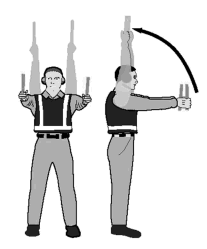 | |||
| 3. Point both arms upward, move and extend arms outward to sides of body and point with wands to direction of next signalman or taxi area. | Proceed to next signalman or as directed by tower/ground control |  | |||
| 4. Bend extended arms at elbows and move wands up and down from chest height to head. | Straight ahead |  | |||
| 5(a) With right arm and wand extended at a 90-degree angle to body, make “come ahead” signal with left hand. The rate of signal motion indicates to pilot the rate of aircraft turn. | Turn left (from pilot’s point of view) | 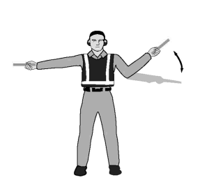 | |||
| 5(b) With left arm and wand extended at a 90-degree angle to body, make “come ahead” signal with right hand. The rate of signal motion indicates to pilot the rate of aircraft turn. | Turn right (from pilot’s point of view) |  | |||
| 6(a) Fully extend arms and wands at a 90-degree angle to sides and slowly move to above head until wands cross. | Normal stop |  | |||
| 6(b) Abruptly extend arms and wands to top of head, crossing wands. | Emergency stop | 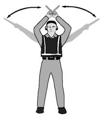 | |||
| 7(a) Raise hand just above shoulder height with open palm. Ensuring eye contact with flight crew, close hand into a fist. Do not move until receipt of “thumbs up” acknowledgement from flight crew. | Set brakes | 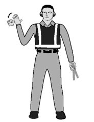 | |||
| 7(b) Raise hand just above shoulder height with hand closed in a fist. Ensuring eye contact with flight crew, open palm. Do not move until receipt of “thumbs up” acknowledgement from crew. | Release brakes | 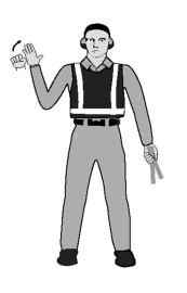 | |||
| 8(a) With arms and wands fully extending above head, move wands inwards in a “jabbing” motion until wands touch. Ensure acknowledgement is received from flight crew. | Chocks inserted | 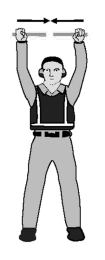 | |||
| 8(b) With arms and wands fully extended above head, move wands outward in “jabbing” motion. Do not remove chocks until authorised by crew. | Chocks removed | 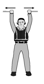 | |||
| 9. Raise right arm to head level with wand pointing up and start a circular motion with hand; at the same time, with left arm raised above head level, point to engine to be started. | Start engine(s) | 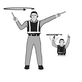 | |||
| 10. Extend arm with wand forward of body at shoulder level; move hand and want to top of left shoulder and draw wand to top of right shoulder in a slicing motion across throat. | Cut engine(s) |  | |||
| 11. Move extended arms downwards in a “patting” gesture, moving wands up and down from waist to knees. | Slow down | 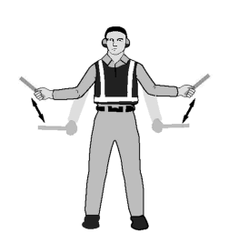 | |||
| 12. With arms down and wands toward ground, wave either right or left wand up and down indicating engine(s) on left or right side respectively should be slowed down. | Slow down engine(s) on indicated side |  | |||
| 13. With arms in front of body at waist height, rotate arms in a forward motion. To stop rearward movement, use signal 6(a) or 6(b). | Move Back | 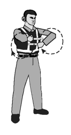 | |||
| 14(a) Point left arm with wand down and bring right arm from overhead vertical position to horizontal forward position, repeating right-arm movement. | Turns while backing (for tail to starboard) | 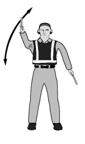 | |||
| 14(b) Point right arm with wand down and bring left arm from overhead vertical position to horizontal position, repeating left-arm movement. | Turns while backing (for tail to port) |  | |||
| 15. Raise right arm to head level with wand pointing up or display hand with “thumbs up”; left arm remains at side by knee. | Affirmative/all clear—This signal is also used as a technical/servicing communication signal. | 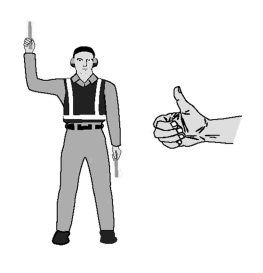 | |||
| 16. Fully extend arms and wands at a 90-degree angle to sides. | Hover | 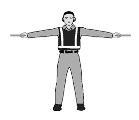 | |||
| 17. Fully extend arms and wands at a 90-degree angle to sides and, with palms turned up, move hands upwards. Speed of movement indicates rate of ascent. | Move upwards | 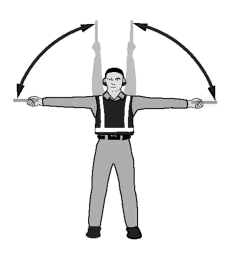 | |||
| 18. Fully extend arms and wands at a 90-degree angle to sides and, with palms turned down, move hands downwards. Speed of movement indicates rate of descent. | Move downwards | 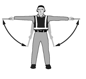 | |||
| 19(a) Extend arm horizontally at a 90-degree angle to right side of body. Move other arm in same direction in a sweeping motion. | Move horizontally left (from pilot’s point of view) |  | |||
| 19(b) Extend arm horizontally at a 90-degree angle to left side of body. Move other arm in same direction in a sweeping motion. | Move horizontally right (from pilot’s point of view) |  | |||
| 20. Cross arms with wands downwards and in front of body. | Land | 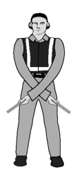 | |||
| 21. Move right-hand wand in a “fanning” motion from shoulder to knee, while at the same time pointing with left-hand wand to area of fire. | Fire |  | |||
| 22. Fully extend arms and wands downwards at a 45-degree angle to sides. Hold position until aircraft is clear for next manoeuvre. | Hold position/stand by |  | |||
| 23. Perform a standard salute with right hand and/or wand to dispatch the aircraft. Maintain eye contact with flight crew until aircraft has begun to taxi. | Dispatch aircraft | 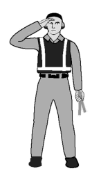 | |||
| 24. Extend right arm fully above head and close fist or hold wand in horizontal position; left arm remains at side by knee. | Do not touch controls (technical/servicing communication signal) | 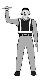 | |||
| 25. Hold arms fully extended above head, open left hand horizontally and move finger tips of right hand into a touch open palm of left hand (forming a “T”). At night, illuminated wands can also be used to form the “T” above head. | Connect ground power (technical/servicing communication signal) |  | |||
| 26. Hold arms fully extended above head with finger tips of right hand touching open horizontal palm of left hand (forming a “T”); then move right hand away from the left. Do not disconnect power until authorised by flight crew. At night illuminated wands can also be used to form the “T” above head. | Disconnect power (technical/servicing communication signal) |  | |||
| 27. Hold right arm straight out at 90 degrees from shoulder and point wand down to ground or display hand with “thumbs down”; left hand remains at side by knee. | Negative (technical/servicing communication signal) | 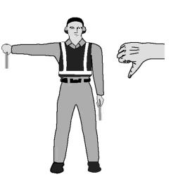 | |||
| 28. Extend both arms at 90 degrees from body and move hands to cup both ears. | Establish communication via interphone (technical/servicing communication signal) |  | |||
| 29. With right arm at side and left arm raised above head at a 45-degree angle, move right arm in a sweeping motion towards top of left shoulder. | Open/close stairs (technical/servicing communication signal)—This signal is intended mainly for aircraft with the set of integral stairs at the front |  | |||
Marshalling signals (from a pilot of an aircraft to a marshaller)
62. Each of the signals described in column 1 of Table 6, when made by a pilot in an aircraft to a marshaller on the ground, shall have the meanings specified in column 2 of the Table.
Table 6—Meaning of Marshalling Signals (from a pilot of an aircraft to a marshaller)
Column 1 | Column 2 |
|---|---|
Description of Signal | Meaning of Signal |
| 1. Raise arm and hand with fingers extended horizontally in front of face, then clench fist. | Brakes engaged. |
| 2. Raise arm with fist clenched horizontally in front of face, then extend fingers. | Brakes released. |
| 3. Arms extended palms facing outwards, move hands inwards to cross in front of face. | Insert chocks. |
| 4. Hands crossed in front of face, palms facing outwards, move arms outwards. | Remove chocks. |
| 5. Raise the number of fingers on one hand indicating the number of the engine to be started. For this purpose the aircraft engines shall be numbered in relation to the marshaller facing the aircraft, from his right to his left. For example, No. 1 engine shall be the port outer engine, No. 2 engine shall be the port inner engine, No. 3 engine shall be the starboard inner engine and No. 4 engine shall be the starboard outer engine. | Ready to start engines. |
Distress, urgency and safety signals
63.—(1) The following signals, given either together or separately before the sending of a message, signify that an aircraft is threatened by grave and imminent danger and requests immediate assistance—
(a)by radiotelephony—
the spoken word ‘MAYDAY’;
(b)by visual signalling—
(i)the signal SOS (… --- …);
(ii)a succession of pyrotechnic lights fired at short intervals each showing a single red light;
(iii)a parachute flare showing a red light;
(c)by sound signalling other than radiotelephony—
(i)the signal SOS (… --- …);
(ii)a continuous sounding with any sound apparatus.
(2) The following signals, given either together or separately, before the sending of a message, signify that the pilot-in-command of the aircraft wishes to give notice of difficulties which compel it to land but that he does not require immediate assistance—
(a)a succession of white pyrotechnic lights;
(b)the repeated switching on and off of the aircraft landing lights;
(c)the repeated switching on and off of its navigation lights, in such a manner as to be clearly distinguishable from the flashing navigation lights described in rule 49.
(3) The following signals, given either together or separately, indicate that the pilot-in-command of the aircraft has an urgent message to transmit concerning the safety of a ship, aircraft, vehicle or other property or of a person on board or within sight of the aircraft from which the signal is given—
(a)by radiotelephony—
the repeated spoken word, ‘PAN PAN’;
(b)by visual signalling—
the signal XXX (- .. -- .. -- .. -);
(c)by sound signalling other than radiotelephony—
the signal XXX (- .. -- .. -- .. -).