ANNEX IU.K. TECHNICAL REQUIREMENTS
[F1Appendix 5
Textual Amendments
F1Inserted by Commission Regulation (EU) 2019/1892 of 31 October 2019 amending Regulation (EU) No 1230/2012 as regards type-approval requirements for certain motor vehicles fitted with elongated cabs and for aerodynamic devices and equipment for motor vehicles and their trailers (Text with EEA relevance).
Three-dimensional cab envelope U.K.
1. General procedure for the checking of conformity of the motor vehicle with the parameters relating to the three-dimensional cab envelope U.K.
1.1. Vertical boundaries of the motor vehicle cab assessment zone U.K.
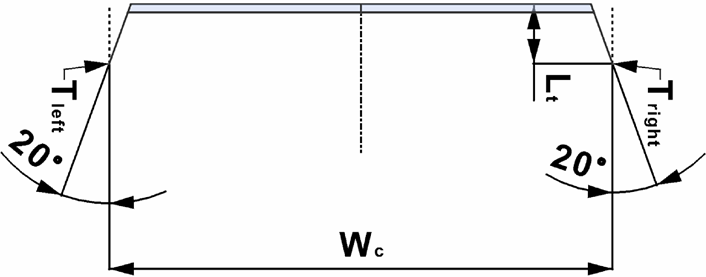
1.1.1. The maximum width of the vehicle at cab location W c shall be taken forward of the vertical transverse plane located at the foremost axle of the motor vehicle. The items listed in Appendix 1 shall not be taken into account for the purposes of this measurement. U.K.
1.1.2. The assessment zone of the motor vehicle’s cab location shall be considered in such a way that it corresponds with the maximum width W c . The zone shall be bounded by vertical longitudinal planes that are parallel to the longitudinal median plane of the motor vehicle and that are distance W c apart. U.K.
1.1.3. The horizontal longitudinal distance L t shall be established from the most forward point of the motor vehicle’s cab location taken at a height ≤ 2 000 mm from the ground measured in unladen condition. U.K.
The distance L t shall be set at 200 mm for the purpose of this assessment (see figure 1).
The rear side of the assessment zone shall be bounded by a vertical transverse plane, perpendicular to the longitudinal median plane of the motor vehicle, that is located rearward of the abovementioned most forward point by distance L t .
Figure 1 3D envelope U.K.
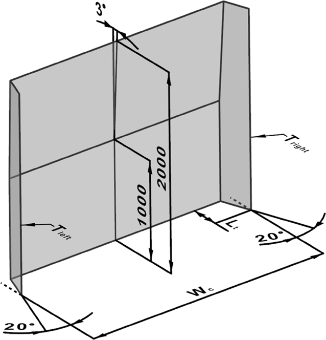
1.1.4. The intersections of the rear plane forming the side of the assessment zone with both angled outboard planes, lines T left and T right , shall be considered for the purpose of point 1.3.3.2. (see figure 2). U.K.
Figure 2 3D envelope U.K.
1.2. Horizontal boundaries of the motor vehicle cab assessment zone U.K.
1.2.1. In the assessment zone, the lower front fascia boundary line shall be set at ground level and the upper front fascia boundary line shall be set at 2 000 mm above the ground as measured in unladen condition. U.K.
1.3. Specific provisions for the motor vehicle cab assessment zone U.K.
1.3.1. For the purposes of this Appendix, the front fascia at the motor vehicle’s cab location shall be considered, regardless of type of material. However, the items listed in Appendix 1 shall not be taken into account. U.K.
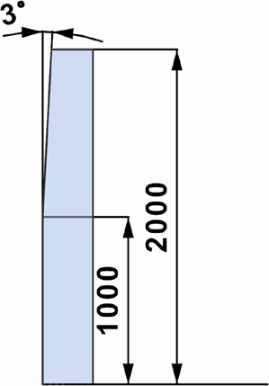
1.3.2. Rake of the front of the cab U.K.
1.3.2.1. For the purposes of this Appendix, ‘ rake ’ shall be considered, meaning the rearward inclination of the motor vehicle’s front fascia at the cab location from the vertical, where any point located above another point lies rearward of that other point. U.K.
1.3.2.2. For the assessment zone of the rake, the most forward point of the motor vehicle’s cab location as referred to in point 1.1.3. shall be considered. U.K.
The vertical transverse plane through the most forward point of the cab, taken at a height of ≤ 2 000 mm from the ground measured in unladen condition, shall be considered as regards its intersection with the horizontal plane that is located at the height of 1 000 mm. The intersecting line shall then be taken as the base envelope line to assess the vehicle cab’s rake in the given assessment zone.