[F1ANNEX II U.K. Braking Tests and performance of braking systems
Textual Amendments
Appendix (See point 1.1.4.2) Distribution of braking effort among vehicle axles
3. REQUIREMENTS FOR MOTOR VEHICLES U.K.
3.1. Two-axle vehicles U.K.
3.1.1. (1) For all categories of vehicles for k values between 0,2 and 0,8: U.K.

For all states of load of the vehicle, the adhesion curve of the front axle shall be situated above that of the rear axle:
for all braking rates of between 0,15 and 0,8 in the case of vehicles of category M 1 .
However, for vehicles of this category over the range of z values between 0,3 and 0,45, an inversion of the adhesion utilisation curves is permitted provided that the adhesion utilisation curve of the rear axle does not exceed by more than 0,05 the line defined by the formula k = z (line of ideal adhesion utilisation — see diagram 1A),
for all braking rates of between 0,15 and 0,5 in the case of vehicles of category N 1 (2) .
This condition is also considered satisfied if, for braking rates between 0,15 and 0,30, the adhesion utilisation curves for each axle are situated between two parallels to the line of ideal adhesion utilisation given by the equations k = z + 0,08 and k = z - 0,08 as shown in diagram 1C, where the adhesion utilisation curve for the rear axle may cross the line k = z - 0,08 and, for braking rates between 0,3 and 0,5, complies with the relation z ≥ k - 0,08 and between 0,5 and 0,61 with the relation z ≥ 0,5 k + 0,21,
for all braking rates of between 0,15 and 0,30 in the case of other categories. This condition is also considered satisfied if, for braking rates between 0,15 and 0,30 the adhesion utilisation curves for each axle are situated between two parallels to the line of ideal adhesion utilisation given by the equations k = z + 0,08 and k = z - 0,08 as shown in diagram 1B, and the adhesion utilisation curve for the ear axle, for braking rates z ≥ 0,3 complies with the relation:

3.1.2. In the case of a motor vehicle authorised to tow trailers of category O 3 or O 4 fitted with compressed-air braking systems: U.K.
3.1.2.1. When tested with the energy source stopped, the supply line blocked off and a reservoir of 0,5 litre capacity connected to the control line, and the system at cut-in and cut-out pressures, the pressure at full application of the service braking system control shall be between 6,5 and 8,5 bar at the coupling heads of the supply line and the control line, irrespective of the load condition of the vehicle. These pressures shall be demonstrably present in the towing vehicle when uncoupled from the trailer. The compatibility bands in diagrams 2, 3 and 4A of this Appendix to Annex II shall not be extended beyond 7,5 bar. U.K.
3.1.2.2. It shall be ensured that at the coupling head of the supply line a pressure of at least 7 bar is available when the system is at cut-in pressure; this pressure shall be demonstrated without applying the service braking system. U.K.
3.1.3. Verification of the requirements of point 3.1.1 U.K.
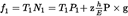
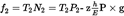
In order to verify the requirement of point 3.1.1, the manufacturer shall provide the adhesion utilisation curves for the front and rear axles calculated by the formulae:
The graphs shall be plotted for both the following load conditions:
Unladen, in running order with the driver on board.
In the case of a vehicle presented as a bare chassis-cab, a supplementary load may be added to simulate the mass of the body, not exceeding the minimum mass declared by the manufacturer in Annex XVIII.
Laden.
Where provision is made for several possibilities of load distribution, the one whereby the front axle is the most heavily laden shall be the one to be taken into consideration.
3.1.4. Towing vehicles other than tractive units for semi-trailers U.K.
3.1.4.1. In the case of a motor vehicle authorised to tow trailers of category O 3 or O 4 fitted with compressed-air braking systems, the permissible relationship between the braking rate U.K.

and the pressure p m shall be within the areas shown in diagram 2.
3.1.5. Tractive units for semi-trailers U.K.
3.1.5.1. Tractive units with unladen semi-trailer U.K.
An unladen articulated combination is considered to be a tractive unit in running order, with the driver on board, coupled to an unladen semi-trailer. The dynamic load of the semi-trailer on the tractive unit shall be represented by a static mass, mounted at the location of the king pin of the fifth wheel coupling, equal to 15 % of the maximum mass on the coupling. The braking forces shall continue to be regulated between the state of the tractive unit with semi-trailer (unladen) and that of the tractive unit alone, (without semi-trailer); the braking forces relating to the tractive unit alone shall be verified.
3.1.5.2. Tractive units with laden semi-trailer U.K.
A laden articulated combination shall be considered to be a tractive unit in running order with the driver on board coupled to a laden semi-trailer. The dynamic load of the semi-trailer on the tractive unit shall be represented by a static mass P s , mounted at the location of the king pin of the fifth wheel coupling, equal to:

where P so represents the difference between the maximum laden mass of the tractive unit and its unladen mass.
For h the following value shall be taken:

where:
h 0 is the height of the centre of gravity of the tractive unit
h s is the height of the coupling on which the semi-trailer rests
P 0 is the unladen mass of the solo tractive unit

3.1.5.3. In the case of a vehicle fitted with a compressed-air braking system, the permissible relationship between the braking rate U.K.

and the pressure p m shall be within the areas shown in diagram 3.
3.2. Vehicles with more than two axles U.K.
The requirements of point 3.1 shall apply to vehicles with more than two axles. The requirements of point 3.1.1 with respect to wheel-lock sequence shall be considered to be met, if in the case of braking rates of between 0,15 and 0,30, the adhesion used by at least one of the front axles shall be greater than that used by at least one of the rear axles.]
[F1The provisions of point 3.1.1 do not affect the requirements of Annex II relating to the braking efficiency. However, if, when verifying the provisions of point 3.1.1 braking efficiencies are obtained which are higher than those prescribed in Annex II, the provisions relating to the adhesion utilisation curve shall be applied within the areas of diagrams IA and IB defined by the straight lines k = 0,8 and z = 0,8.
Vehicles of category N 1 with a laden/unladen rear axle loading ratio not exceeding 1,5 or having a maximum mass of less than 2 tonnes will have to comply with the requirements for category M 1 vehicles of this point from 1 October 1990.]
Textual Amendments