- Y Diweddaraf sydd Ar Gael (Diwygiedig)
- Gwreiddiol (a wnaed Fel)
The Traffic Signs Regulations and General Directions 2016
You are here:
- Offerynnau Statudol y Deyrnas Unedig
- 2016 No. 362
- Schedules only

Pa Fersiwn
Rhagor o Adnoddau
Status:
Dyma’r fersiwn wreiddiol (fel y’i gwnaed yn wreiddiol). This item of legislation is currently only available in its original format.
Regulation 2
SCHEDULE 1Definitions
(1) Term | (2) Meaning |
|---|---|
“abnormal transport unit” | (a) a motor vehicle or a vehicle combination— (i) the overall length of which, inclusive of the load (if any) on the vehicle or the combination, exceeds 61 feet 6 inches (18.75 metres); (ii) the overall width of which, inclusive of the load (if any) on the vehicle or the combination, exceeds 9 feet 6 inches (2.9 metres); or (iii) the maximum gross weight of which exceeds 44 tonnes; or (b) a motor vehicle, or a vehicle combination, which is incapable of proceeding, or is unlikely to proceed, over a level crossing at a speed exceeding 5 mph |
“actively managed hard shoulder” | a hard shoulder along which, by virtue of regulations under section 17(2) and (3) of the 1984 Act(1), vehicular traffic may be driven at times for the time being indicated by signs in accordance with those regulations |
“administrative area” | (a) United Kingdom; (b) England; (c) Scotland; (d) Wales; (e) a county or district in England for the purposes of the Local Government Act 1972(2); (f) a county or county borough in Wales for the purposes of the Local Government Act 1972; (g) a local government area for the purposes of the Local Government etc. (Scotland) Act 1994(3); (h) a London Borough; (i) Greater London; (j) the City of London; (k) the Isles of Scilly |
“all-purpose road” | a road that is not a motorway |
“amber light beacon” | a beacon which shows an intermittent amber light and which complies with the beacon requirements |
“articulated vehicle” | a motor vehicle with a trailer so attached to it as to be partially superimposed upon it |
“backing board” | includes any background (except a wall to which a sign is fixed) against which a sign is displayed |
“beacon requirements” | the requirements applying to beacons and which are specified in Part 10 of Schedule 13 |
“blood and blood components” | have the same meaning as in regulation 1(3) of the Blood Safety and Quality Regulations 2005(4) |
“blood service purposes” | the collection or distribution of blood or blood components by NHS Blood and Transplant(5), the Scottish National Blood Transfusion Service(6), the Welsh Blood Service(7) or the Northern Ireland Blood Transfusion Service(8) |
“blue light beacon” | a beacon showing an intermittent blue light which complies with the beacon requirements |
“breakdown vehicle” | has the same meaning as in regulation 3(2) of the Road Vehicle Lighting Regulations 1989(9) |
“British Standard for retroreflecting studs” | British Standard BS EN 1463-1: 2009(10) on retro reflecting road studs when read with British Standard BS EN 1463-2: 2000(11) on road test performance for retroreflecting road studs |
“bus” | unless the context requires otherwise— a motor vehicle constructed or adapted to carry more than 8 passengers (exclusive of the driver); or a local bus |
“bus lane” | a traffic lane reserved for— (a) buses; and (b) where indicted on a sign, authorised vehicles, pedal cycles, solo motor cycles or taxis |
“carriageway” | (a) in relation to a highway in England or Wales, or a road in Scotland, a way constituting or comprised in the highway or road being a way over which the public has a right of way for the passage of vehicles or class of vehicles, and (b) in relation to any other road in England or Wales to which the public has access, that part of the road to which vehicles have access, but does not include in either case any central reservation |
“central reservation” | (a) any land between the carriageways of a road comprising two carriageways; or (b) any permanent work (other than a traffic island) in the carriageway of a road, which separates the carriageway or, as the case may be, the part of the carriageway, which is to be used by traffic moving in one direction from the carriageway or part of the carriageway which is to be used (whether at all times or at particular times only) by traffic moving in the other direction |
“ceremonial area” | (a) in relation to England, an area that is to be regarded as a county for the purposes of the Lieutenancies Act 1997(12) (“the 1997 Act”) by virtue of paragraph 3 of Schedule 1 to that Act; (b) in relation to Wales, a preserved county within the meaning of paragraph 6 of Schedule 1 to the 1997 Act; (c) in relation to Scotland, an area for the purposes of the 1997 Act within the meaning of paragraph 7 of Schedule 1 to that Act |
“circular sign” | an upright sign which is of a circular shape |
“civil emergency” | an emergency within the meaning of section 1 of the Civil Contingencies Act 2004(13) or terrorism within the meaning of section 1 of the Terrorism Act 2000(14) |
“civil emergency warning or information” | a warning or information about a civil emergency or the prospect of a civil emergency |
“congestion charging zone” | an area in which the roads are designated for the purposes of a scheme for imposing charges in respect of the keeping or use of motor vehicles on roads |
“contraflow” | a carriageway, or part of a carriageway, of a road where— (a) traffic is authorised to proceed in the opposite direction to the usual direction of traffic on that part; or (b) a specified class of traffic is authorised to proceed in the opposite direction to other traffic on that carriageway |
“controlled parking zone” | either— (a) an area— (i) in which every part of every road is subject to a prohibition indicated by single or double yellow lines or single or double yellow kerb markings (except where parking spaces have been provided, where entrance to or exit from the road is made, where there is a prohibition or restriction on waiting, stopping, loading or unloading indicated by a different sign or where there is a crossing) whether or not an upright sign to indicate the same prohibition is placed in conjunction with the line or kerb marking; and (ii) into which each entrance for vehicular traffic has been indicated by the sign provided for at item 1 or 3 of the sign table in Part 3 of Schedule 5; or (b) an area— (i) in which at least one sign provided for at item 3 of the sign table in Part 3 of Schedule 4 has been placed on each side of every road; and (ii) in which each entrance for vehicular traffic has been indicated by a sign provided for at item 4 of the sign table in Part 3 of Schedule 5 |
“corresponding EEA standard” | a standard, code of practice or technical specification of a kind referred to in regulation 12 which requires a level of performance equivalent to that required by a British Standard |
“cycle lane” | part of a carriageway of a road reserved for pedal cycles which is separated from the rest of the carriageway— (a) if it may not be used by vehicles other than pedal cycles, by the marking provided for at item 7 of the sign table in Part 6 of Schedule 9; (b) if it may be used by vehicles other than pedal cycles when clear of pedal cycles, by the marking provided for at item 2 or 3 of the sign table in Part 4 of Schedule 11 |
“cycle track” | |
“depressible stud” | a stud fitted in such a way that the height by which it, or part of it, projects above the surface of the adjacent carriageway is reduced when pressure is applied from above |
“designated lane” | a traffic lane reserved, by an order under section 1, 6, 9, 14, 16A or 19 of the 1984 Act(17) (traffic regulation orders and orders similar to traffic regulation orders), for use by such class of vehicular traffic as is, by the order, specified for the purpose of that reservation |
“disabled badge holder symbol” | refers to this symbol: |
“double red lines” | the road marking provided for at item 11 of the sign table in Part 4 of Schedule 7 |
“double yellow kerb marking” | the road marking provided for at item 3 of the sign table in Part 4 of Schedule 7 |
“double yellow lines” | the road marking provided for at item 1 of the sign table in Part 4 of Schedule 7 |
“driver” | (a) in relation to a vehicle which is a motor cycle or pedal cycle, the person riding the vehicle who is, or is purporting to be, in control of it; and (b) in relation to an abnormal transport unit— (i) where that unit is a single motor vehicle the driver of that vehicle; or (ii) where that unit is a vehicle combination, the driver of the only or the foremost motor vehicle forming part of that combination |
“dual carriageway road” | a road which comprises a central reservation and “all-purpose dual carriageway road” means a dual carriageway road which is not a motorway |
“emergency vehicle” | has the same meaning as in regulation 3(2) of the Road Vehicle Lighting Regulations 1989 |
“equestrian crossing” | a place on the carriageway of a road— (a) at which provision is made for equestrian traffic to cross the carriageway; and (b) the presence of which is indicated by a combination of— (i) the traffic light signals provided for at item 1, 3 or 4 of the sign table in Part 2 of Schedule 14; (ii) the signals provided for at— (aa) items 15 and 16 of that table; or (bb) the signal provided for at item 17 (whether or not placed with the signal provided for at item 18); and (iii) the road marking provided for at item 55 or 56 |
“excursion or tour” | has the meaning given in section 137(1) of the Transport Act 1985(18) |
“fire and rescue authority” | is to be construed in accordance with section 1 of the Fire and Rescue Services Act 2004(19) |
“fluorescent green-yellow” | has the same meaning as in the British Standard for retroreflecting studs |
“General Directions” | the Traffic Signs General Directions 2016(20) |
“give way sign” | the upright sign provided for at item 2 in the Part 2 sign table in Schedule 9 |
“goods vehicle” | a motor vehicle or trailer constructed or adapted for use for the carriage or haulage of goods or burden of any description (and a reference in a diagram to “t” is to the maximum gross weight in tonnes) |
“hard shoulder” | in relation to a motorway in England and Wales, has the meaning given by regulation 3(1)(e) of the Motorways Traffic (England and Wales) Regulations 1982(21) and, in relation to a motorway in Scotland, regulation 2(1) of the Motorways Traffic (Scotland) Regulations 1995(22) |
“historic county area” | an area that at the time of the placing of the sign in question is not, but was, a county |
“hours of darkness” | the time between half an hour after sunset and half an hour before sunrise |
“junction” | a road junction |
“layout or character” | in relation to a road, means the layout or character of the road itself and does not include the layout or character of any land or premises adjacent to the road |
“leisure facility” | (a) those facilities of a description in column 2 of— (i) items 4 to 12 in Part 14 of Schedule 12; (ii) items 4, 12, 18, 34 to 38, 43, 44, 60, 63, 64 and 67 of Part 15 of Schedule 12; (iii) item 4 of Part 16 of Schedule 12; (iv) item 4 of Part 18 of Schedule 12; (b) a tourist hostel |
“level crossing” | a place where a road is crossed by a railway or tramway on a reserved track on the same level |
“local” | when shown on a bus symbol, indicates that the road or the traffic lane on or near which the sign has been placed must be used only by local buses. |
“local bus” | a public service vehicle used for the provision of a local service not being an excursion or tour |
“local service” | has the meaning given in section 2 of the Transport Act 1985 |
“major road” | the road at a junction into which there emerges vehicular traffic from a minor road |
“matrix sign” | a light signal for conveying information or a warning, requirement, restriction, prohibition or speed limit to traffic on a motorway, or an all-purpose dual carriageway road |
“maximum gross weight” | (a) in the case of a motor vehicle not drawing a trailer or in the case of a trailer, its maximum laden weight; (b) in the case of an articulated vehicle, its maximum laden weight (if it has one) and otherwise the aggregate maximum laden weight of all the individual vehicles forming part of that articulated vehicle; (c) in the case of a motor vehicle (other than an articulated vehicle) drawing one or more trailers, the aggregate maximum laden weight of the motor vehicle and the trailer or trailers drawn by it |
“maximum laden weight” | in relation to a vehicle (including a vehicle which is a trailer) means— (a) in the case of a vehicle as respects which a gross weight not to be exceeded in Great Britain is specified in construction and use requirements (as defined by section 41(7) of the Road Traffic Act 1988(23)), the weight so specified; (b) in the case of a vehicle as respects which no such weight is so specified, the weight which the vehicle is designed or adapted not to exceed when in normal use and travelling on a road laden; |
“maximum speed limit sign” | the sign provided for at item 1 of the sign table in Part 2 of Schedule 10 |
“method of illumination” | is a reference to illumination by internal or external lighting or reflectorisation |
“minor road” | a road on which, at its junction with another road, there is placed the sign at item 1 or 2 of the sign table in Part 2 of Schedule 9 or the road marking at item 3 of the sign table in Part 6 of that Schedule |
“minor route” | a road which, under the system for assigning identification numbers to roads administered by the Secretary of State, Scottish Ministers or Welsh Ministers, has not been assigned a number prefixed by A, B or M |
“mobile road works” | road works carried out by or from a vehicle or vehicles which move slowly along the road or which stop briefly from time to time along that road |
“motorway” | a special road which— (a) in England and Wales (except if otherwise provided by or under regulations made under, or having effect as if made under, section 17 of the 1984 Act(24)), can be used by traffic only of Class I or Class II as specified in Schedule 4 to the Highways Act 1980(25); (b) in Scotland, can be used by traffic only of Class I or Class II as specified in Schedule 3 to the Roads (Scotland) Act 1984(26) |
“mph” | miles per hour |
“national promoter of tourism” | |
“national speed limit” | any prohibition imposed on a road by the 70 miles per hour, 60 miles per hour and 50 miles per hour (Temporary Speed Limit) Order 1977(30) or by regulation 3 of the Motorways Traffic (Speed Limits) Regulations 1974(31) |
“NHS ambulance service” | (a) an NHS trust or NHS foundation trust established under the National Health Service Act 2006(32) which has a function of providing ambulance services; (b) an NHS trust established under the National Health Service (Wales) Act 2006(33) which has a function of providing ambulance services; (c) the Scottish Ambulance Service Board |
“non-primary route” | a route, not being a primary route or a motorway or part of a primary route or of a motorway |
“panel” | a rectangular or square part of a sign which is distinguishable from the other part or parts of the sign by being of a contrasting colour or having a border of a contrasting colour |
“Parallel controlled area” | a length of carriageway— (a) which— (i) is adjacent to a Parallel crossing; and (ii) in the manner shown in the diagram at item 53 of the sign table in Part 2 of Schedule 14, has a zig-zag line, of the type provided for at that item, marked along each of its edges (with or without zig-zag lines also marked down its centre) and give way markings, of the type provided for at item 54 of that table, marked parallel to the crossing; and (b) in or near which no other signs or markings have been placed except ones— (i) comprised in the combination of signs and markings indicating the presence of the facility for crossing; or (ii) provided for at item— (aa) 3, 7, 8 or 10 in the sign table in Part 2 of Schedule 3; (bb) 2 or 73 in the sign table in Part 2 of Schedule 11; or (cc) 18, 28 or 33 in the sign table in Part 4 of Schedule 11 |
“Parallel crossing” | a place on the carriageway— (a) where provision is made for pedestrians and cyclists to cross the carriageway; (b) the presence of which is indicated by— (i) a yellow globe of the type provided for at item 27 of the sign table in Part 2 of Schedule 14 at each end of the crossing (except that globes need not be present at a crossing that only crosses a cycle track); (ii) in respect of the part of the crossing for pedestrians, the black and white stripes shown in the diagram at item 53 and in respect of which provision is made at paragraph 18 of Part 1 of that Schedule (including provision for the black stripes to be a different colour); and (iii) in respect of the part of the crossing for cyclists, the markings provided for at item 57 together with, where used, the cycle symbols shown in the diagram at item 53 of that sign table; and (c) the limits of which are indicated— (i) in so far as they relate to the part for pedestrians, the stripes; and (ii) in so far as they relate to the part for cyclists, the marking at item 57 |
“parking place identifier” | any symbol, logo, letter, numeral or name (or combination) of any size in a colour that contrasts with the background on which they are placed, whether or not placed on a patch which may be of any colour, which indicates or identifies an area or location in which restrictions on the parking of vehicles apply by reference to a particular parking place or group of parking places |
“pedal cycle” | a unicycle, bicycle, tricycle or cycle having four or more wheels, not being in any case mechanically propelled unless it is an electrically assisted pedal cycle that is not treated as a motor vehicle for the purposes of the 1984 Act(34) |
“pedestrian zone” | an area— (a) which has been laid out to improve amenity for pedestrians; and (b) to which the entry of vehicles is prohibited or restricted |
“pedestrian and cycle zone” | an area— (a) which has been laid out to improve amenity for pedestrians and cyclists; and (b) to which the entry of vehicles, except pedal cycles, is prohibited or restricted |
“permit identifier” | any upper case letter or letters, with or without a number, whether or not placed on a patch which may be of any colour, where the letter and, as the case may be, number are of any size, in a colour that contrasts with the background on which they are placed and indicate a type of permit |
“permit parking area” | an area— (a) into which each entrance for vehicular traffic has been indicated by the sign provided for at item 5 of the sign table in Part 3 of Schedule 5; and (b) where any parking place within that area reserved for the use of the permit holders as indicated on that sign is not shown by markings on the road (whether or not an upright sign is placed next to, or near, such a parking place to indicate that only the permit holders in question may use the place) |
“plate” | a sign which may or must (as indicated in the General Directions) be used to supplement or qualify the message conveyed by an upright sign. And an “associated plate” refers to a plate which supplements or qualifies a particular upright sign |
“police vehicle” | a vehicle being used for police purposes or operating under the instructions of a chief officer of police |
“portable signal controlled pedestrian facility” | a place on the carriageway— (a) which is not a section 25 crossing; (b) where temporary provision is made for pedestrians to cross the carriageway; (c) the presence of which is indicated by the signs provided for in the sign table in Part 2 of Schedule 14 at item 2, item 60 and — (i) item 9 (with or without item 10) and either item 11 or 12; or (ii) item 13; and (d) the presence of which may in addition be indicated by— (i) either or both of the road markings provided for at item 46 (stop line) and 55 (crossing marking) of the table; and (ii) where— (aa) all streams of vehicular traffic are stopped only for the purpose of enabling pedestrians to cross the carriageway; and (bb) both the stop line and crossing markings provided for at items 46 and 55 respectively are also placed, the road marking provided for at item 51 of the table |
“primary route” | a route, not being a route comprising any part of a motorway, in relation to which a determination has been made that it provides the most satisfactory route for through traffic between places of traffic importance under the administrative system for so determining that is the responsibility of the Secretary of State, Scottish Ministers or Welsh Ministers in England, Scotland and Wales respectively |
“principal road” | (a) in England and Wales, a road classified as a principal road in accordance with section 12 of the Highways Act 1980(35) (whether as falling within subsection (1) or classified under subsection (3)); (b) in Scotland, a road classified as a principal road in accordance with section 11(1) of the Roads (Scotland) Act 1984(36) |
“Puffin controlled area” | a length of carriageway— (a) which is adjacent to a Puffin crossing, has a zig-zag line marked along each of its edges (with or without zig-zag lines also marked down its centre) and is shown by the markings in the diagram at item 51 of the sign table in Part 2 of Schedule 14 and stop line markings, of the type provided for at item 46 or 49 of that table, marked parallel to the crossing; and (b) in or near which no other signs or markings have been placed except ones— (i) comprised in the combination of signs and markings indicating the presence of the facility for crossing; or (ii) provided for at item— (aa) 3, 7, 8 or 10 in the sign table in Part 2 of Schedule 3; (bb) 2 or 73 in the sign table in Part 2 of Schedule 11; or (cc) 18, 28 or 33 in the sign table in Part 4 of Schedule 11 |
“Puffin crossing” | a section 25 crossing— (a) where provision is made for pedestrians to cross the carriageway; and (b) the presence of which is indicated by a combination of— (i) the traffic light signals provided for at item 1, 3 or 4 of the sign table in Part 2 of Schedule 14; (ii) the nearside light signals provided for at item 13 (whether or not used with the supplementary nearside signals provided for at item 14) of that table; and (iii) the crossing marking provided for at item 55 of that table |
“red route” | a road in respect of which the prohibition indicated by single or double red lines has been imposed by an order or notice under the 1984 Act (subject to such exceptions as are provided for by such an order or notice). This definition does not apply when “red route” is used in the phrase “red route clearway” |
“red route clearway” | a road in respect of which the prohibition indicated by the sign provided for at item 8 of the sign table in Part 2 of Schedule 7 has been imposed by an order or notice under the 1984 Act (subject to such exceptions as are provided for by such an order or notice) |
“reflectorised” | illuminated by the use of retroreflecting material (and “reflectorisation” is to be construed accordingly) |
“retroreflecting material” | material which reflects a ray of light back towards the source of that light |
“refuge for pedestrians” | a part of a road to which vehicles do not have access and on which pedestrians may wait after crossing one part of the carriageway and before crossing the other |
“restricted parking zone” | an area— (a) into which each entrance for vehicular traffic has been indicated by a sign which includes the symbol and legend at item 2 of the sign table in Part 3 of Schedule 5; and (b) in which none of the road markings at items 1 to 4 of the sign table in Part 4 of Schedule 7 has been placed |
“road maintenance vehicle” | a vehicle which is specially designed or adapted for use on a road by or on behalf of a traffic authority for the purposes of road maintenance |
“road marking” | a sign consisting of a line, mark or legend on a road |
“road works” | works for the improvement, alteration or maintenance of a road and includes— (a) in relation to England and Wales, street works as defined by section 48(3) of the New Roads and Street Works Act 1991(37); (b) in relation to Scotland, road works as defined by section 107(3) of that Act |
“Schedule [x] General Direction” | where [x] is replaced by a number, is a reference to a general direction that, pursuant to general direction 3 in Part 2 of this Instrument, is contained in the Schedule bearing that number |
“school crossing patrol sign” | a sign exhibited by a school crossing patrol for the purpose of stopping a vehicle in accordance with section 28(1) of the 1984 Act and provided for at item 24 of the sign table in Part 2 of Schedule 14 |
“school crossing place” | a place in a road where children cross or seek to cross that road on their way to or from school or on their way from one part of a school to another |
“section 25 crossing” | a Puffin crossing or a Zebra crossing |
“section 25 crossing controlled area” | a Puffin-controlled area or a Zebra-controlled area |
“sign” | a traffic sign or a school crossing patrol sign |
“sign table” | a table in Schedules 2 to 15 that is headed “Sign table” (followed by the Schedule and Part in which the table appears) |
“signal-controlled crossing facility” | an equestrian crossing, a signal-controlled pedestrian facility or a Toucan crossing |
“signal-controlled crossing facility controlled area” | a length of carriageway— (a) which is adjacent to a signal-controlled crossing facility and has a zig-zag line marked along each of its edges (with or without zig-zag lines also marked down its centre) and is shown by the markings in the diagram at item 51 of the sign table in Part 2 of Schedule 14 and stop line markings, of the type provided for at item 46 or 49 of that table, marked parallel to the crossing; and (b) in or near which no other signs or markings have been placed except ones— (i) comprised in the combination of signs and markings indicating the presence of the facility for crossing; or (ii) provided for at item— (aa) 3, 7, 8 or 10 in the sign table in Part 2 of Schedule 3; (bb) 2 or 73 in the sign table in Part 2 of Schedule 11; or (cc) 18, 28 or 33 in the sign table in Part 4 of Schedule 11 |
“signal-controlled pedestrian facility” | a place on the carriageway of a road— (a) which is not a section 25 crossing; (b) where provision is made for pedestrians to cross the carriageway; and (c) the presence of which is indicated by a combination of— (i) the traffic light signals provided for at item 1, 3 or 4 of the sign table in Part 2 of Schedule 14; (ii) the sign provided for at— (aa) item 9 (with or without item 10) and either item 11 or 12 of the sign table in Part 2 of Schedule 14; or (bb) item 13 of the table (whether or not placed with the signal provided for at item 14); and (iii) the road marking provided for at item 55 or 56 of the table |
“single red line” | the road marking provided for at item 12 of the sign table in Part 4 of Schedule 7 |
“single yellow kerb marking” | the road marking provided for at item 4 of the sign table in Part 4 of Schedule 7 |
“single yellow line” | the road marking provided for at item 2 of the sign table in Part 4 of Schedule 7 |
“solo motor cycle” | a motor cycle without a side car |
“special forces purposes” | the use of a vehicle for naval, military or air force purposes where— (a) the person driving the vehicle is a member of a unit of the armed forces of the Crown the maintenance of whose capabilities is the responsibility of the Director of Special Forces or which is for the time being subject to the operational command of that Director; and (b) the vehicle is being driven— (i) in response, or for practice in responding to, a national security emergency by a person who has been trained in driving vehicles at high speeds; or (ii) for the purpose of training a person in driving vehicles at high speeds |
“speed limit” | a maximum or minimum limit of speed on the driving of vehicles on a road— (a) imposed by an order under section 14 of the 1984 Act(38) (temporary prohibition or restriction of traffic on roads); (b) imposed by an order under section 16A of the 1984 Act(39) (special events); (c) imposed by regulations under section 17 of the 1984 Act(40) (traffic regulation on special roads); (d) arising by virtue of the road being restricted for the purposes of section 81 of the 1984 Act (general speed limit for restricted roads); (e) imposed by an order under section 84 of the 1984 Act(41) (speed limits on roads other than restricted roads); (f) imposed by an order under section 88 of the 1984 Act(42) (temporary speed limits); or (g) imposed by or under a local Act, and “maximum speed limit” and “minimum speed limit” are to be construed accordingly |
“stop line” | has the meaning given in paragraph 30 of Part 1 of Schedule 14 |
“stop sign” | the upright sign provided for at item 1 in the Part 2 sign table in Schedule 9 |
“the stopping prohibited symbol” | refers to this symbol: |
“stroke width” | 25% of the x-height |
“structure warning marking” | the markings provided for at items 3 and 4 of the sign table in Part 5 of Schedule 2 which may be used to supplement a triangular or circular sign and in the phrase “associated structure warning marking”, “associated” refers to the marking in question being supplementary to a particular triangular or circular sign |
“stud” | a prefabricated device fixed or embedded in the carriageway of a road |
“system of street-lighting” | the presence on a road of at least three lamps, lit by electricity, provided for the purposes of illuminating the road, and placed no more than— (a) 183 metres apart in England and Wales, or (b) 185 metres apart in Scotland |
“taxi” | (a) in England and Wales, a vehicle licensed under— (b) in Scotland, a taxi licensed under section 10 of the Civic Government (Scotland) Act 1982(45) |
“taxi rank” | an area of carriageway reserved for use by taxis waiting to pick up passengers |
“temporary hazard warning” | a warning about, or information on how to avoid, any temporary hazards caused by— (a) works being executed on or near a road; (b) adverse weather conditions or other natural causes; (c) the failure of street-lighting or malfunction of, or damage to, any other apparatus, equipment or facility used in connection with the road or anything situated on or near or under it; or (d) damage to the road itself |
“temporary information” | (a) information about— (i) the time, date or location of road works; (ii) the expected delay that road works may cause; (iii) convenient routes to be followed on the occasion of a sporting event, an exhibition or any other public gathering which is likely to attract a large volume of traffic; (iv) diversions or alternative routes; (v) check points at which drivers of goods vehicles or public service vehicles may be required to stop; (vi) the availability of new routes or destinations; or (vii) changes in route numbers; (b) information for drivers of wide loads about action to be taken in respect of road works ahead; or (c) requests by the police for information in connection with road traffic accidents |
“temporary statutory provision” | (a) a provision having effect under section 9 or section 14 of the 1984 Act or under a provision referred to in section 66 of that Act(46); (b) a prohibition, restriction or requirement indicated by a sign placed pursuant to section 67 of the 1984 Act(47); or (c) a provision having effect under section 62 of the Roads (Scotland) Act 1984(48) |
“terminal sign” | a sign placed to indicate the point at which a requirement, restriction or prohibition begins or ends |
“Toucan crossing” | a place on the carriageway of a road— (a) where provision is made for both pedestrians and pedal cyclists to cross the carriageway; and (b) the presence of which is indicated by a combination of— (i) the traffic light signals provided for at item 1, 3 or 4 of the sign table in Part 2 of Schedule 14; (aa) the signals provided for at item 19 (with or without item 10) and either item 12 or 20 of the sign table in Part 2 of Schedule 14; or (bb) the signal provided for at item 21 of that table (whether or not placed with the signal provided for at item 22 of the table); and (iii) the road marking provided for at item 55 or 56 of the table |
“tourist destination” | (a) a Tourist Information Centre or Point; (b) a permanently established attraction or facility (other than a leisure facility) which— (i) attracts or is used by visitors to an area; (ii) is open to the public without prior booking during its normal opening hours; and (iii) is recognised as a tourist attraction or facility by the appropriate national promoter of tourism; (c) a village, town or city that is of particular interest to tourists; (d) a route that is of particular interest to tourists |
“Tourist Information Centre” | a staffed information service centre recognised and supported by the appropriate national promoter of tourism |
“Tourist Information Point” | a display of tourist information approved by the appropriate national promoter of tourism or another person or body responsible for promoting tourism for a particular village, town or other area of England, Wales or Scotland |
“traffic lane” | a part of the carriageway intended for use by vehicles travelling in a particular direction or reserved for use by vehicles of a particular type and separated from other parts of the carriageway by road markings |
“traffic light signals” | the light signals provided for at items 1 to 4 of the sign table in Part 2 of Schedule 14 |
“traffic officer” | has the meaning given in section 100(5) of the 1984 Act(49) |
“tramcar” | has the meaning given in section 141A(4) of the 1984 Act(50) |
“triangular sign” | an upright sign which is of a triangular shape |
“trolley vehicle” | has the meaning given in section 141A(4) of the 1984 Act |
“trunk road” | has the meaning given— |
“tunnel restriction code” | any of the codes specified in Chapter 1.9 of Part 1 of Annex A to the European Agreement concerning the International Carriage of Dangerous Goods by Road (ADR) as applicable from 1st January 2015(53) |
“upright sign” | a traffic sign other than a plate, a structure warning marking, a road marking or light signals |
“variable message sign” | a device which complies with the requirements of Part 1 of Schedule 16 and is capable of displaying, at different times, two or more of the following— (a) a sign provided for in Schedule 2 to 13 or 15; (b) a legend provided for in Schedule 16; and (c) a blank grey or a blank black face. |
“vehicle combination” | a combination of vehicles made up of one or more motor vehicles and one or more trailers all of which are linked together when travelling |
“with-flow” | indicates that the bus or cycle lane in question is for the use of traffic of a type permitted to use that lane proceeding in the same direction as general traffic in an adjoining traffic lane |
“x-height” | the height of the lower case “x” in Parts 1 and 2 of Schedule 17 |
“Zebra controlled area” | a length of carriageway— (a) which— (i) is adjacent to a Zebra crossing; and (ii) in the manner shown in the diagram at item 52 of the sign table in Part 2 of Schedule 14, has a zig-zag line, of the type provided for at that item, marked along each of its edges (with or without zig-zag lines also marked down its centre) and give way markings, of the type provided for at item 54 of that table, marked parallel to the crossing; and (b) in or near which no other signs or markings have been placed except ones— (i) comprised in the combination of signs and markings indicating the presence of the facility for crossing; or (ii) provided for at item— (aa) 3, 7, 8 or 10 in the sign table in Part 2 of Schedule 3; (bb) 2 or 73 in the sign table in Part 2 of Schedule 11; or (cc) 18, 28 or 33 in the sign table in Part 4 of Schedule 11 |
“Zebra crossing” | a place on the carriageway— (a) where provision is made for pedestrians to cross the carriageway; (b) the presence of which is indicated by— (i) a yellow globe of the type provided for at item 27 of the sign table in Part 2 of Schedule 14 at each end of the crossing (except that globes need not be present at a crossing that only crosses a cycle track); (ii) the black and white stripes shown in the diagram at item 52 of that table and in respect of which provision is made at paragraph 18 of Part 1 of that Schedule (including provision for the black stripes to be a different colour); and (iii) where used, the marking provided for at item 55 of that table; and (c) the limits of which are indicated by the stripes except that, where used, the limit is indicated by the marking at item 55 |
“zone identifier” | any symbol, logo, letter, numeral or name (or combination) of any size in a colour that contrasts with the background on which they are placed, whether or not placed on a patch which may be of any colour, which indicates or identifies an area or location in which restrictions on the parking of vehicles apply by reference to that area or location |


Regulation 3, Direction 3
SCHEDULE 2Signs that warn of hazards and signs for bridges and other structures
PART 1Provisions applying to signs and plates in Parts 2 and 3
1. A warning of a description in column 2 of an item in the sign table in Part 2 must be conveyed by a triangular sign which is of—
(a)the colour and type provided for in the diagram in column 3; and
(b)the size shown for a sign in the diagram above the table.
2. A warning or information in column 4 of an item in the sign table in Part 2 is for supplementing the warning in column 2 and is to be conveyed by a plate (“a first associated plate”) which—
(a)includes the legend indicated in column 4 in a manner which complies with the requirements as to size provided for in respect of a plate in the diagram above the sign table in Part 2; and
(b)is of the colour and type provided for in that diagram.
3. Where a number is mentioned in column 5 of the sign table in Part 2, the plate provided for at that item number in the sign table in Part 3 (a “supplementary associated plate”) is an associated plate of the triangular sign in question.
4. A provision of Part 7 mentioned (by reference to paragraph number) in column 6 of the sign table in Part 2 applies in relation to the triangular sign in question.
5. A Schedule 2 General Direction mentioned (by reference to paragraph number) in column 7 of the sign table in Part 2 applies in relation to the triangular sign in question.
PART 2Warning signs and associated plates

Sign table — Schedule 2, Part 2
(1) Item | (2) Description | (3) Diagram | (4) First associated plate legend | (5) Supplementary associated plate (by reference to Part 3 sign table item number) | (6) Applicable provisions in Part 7 | (7) Schedule 2 General Directions |
|---|---|---|---|---|---|---|
| 1 | Diagram 504.1 Crossroads ahead (Alternative types) |  | A distance | 1 | 3 | |
| 2 | Diagram 505.1 T-junction ahead (Alternative types) |  | A distance | 1 | 3 | |
| 3 | Diagram 506.1 Side road ahead (Alternative types) | 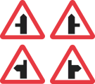 | A distance | 1 | 3 | |
| 4 | Diagram 507.1 Staggered junction ahead (Alternative types) |  | A distance | 1 | 3 | |
| 5 | Diagram 508.1 Traffic merges ahead from left |  | A distance | |||
| 6 | Diagram 509.1 Traffic merges ahead onto main carriageway |  | A distance | |||
| 7 | Diagram 510 Roundabout ahead |  | 1. A distance; or 2. “Adverse camber” | 1 or 4 (or both) | 3 | |
| 8 | Diagram 512 Bend ahead (Alternative types) |  | 1. “Adverse camber”; 2. “Keep in low gear”; or 3. “Oncoming vehicles in middle of road” | 1, 2 or 4 (or any combination) | 3 | |
| 9 | Diagram 512.1 Junction on the outside of a bend ahead (Alternative types) |  | 1. “Adverse camber”; 2. “Keep in low gear”; or 3. “Oncoming vehicles in middle of road” | 1, 2 or 4 (or any combination) | 3 | |
| 10 | Diagram 512.2 Junction on the inside of a bend ahead (Alternative types) |  | 1. “Adverse camber”; 2. “Keep in low gear”; or 3. “Oncoming vehicles in middle of road” | 1, 2 or 4 (or any combination) | 3 | |
| 11 | Diagram 512.3 Crossroads on a bend ahead (Alternative types) |  | 1. “Adverse camber”; 2. “Keep in low gear”; or 3. “Oncoming vehicles in middle of road” | 1, 2 or 4 (or any combination) | 3 | |
| 12 | Diagram 513 Double bend or series of bends ahead (Alternative types) |  | 1. “For” and a distance; 2. “Adverse camber”; 3. “Keep in low gear”; or 4. “Oncoming vehicles in middle of road” | 1, 2 or 4 (or any combination) | 3 | |
| 13 | Diagram 516 Road narrows on both sides ahead |  | 1. A distance; 2. “Single file traffic” with or without an arrow pointing to the left or to the right; 3. “Single file traffic” and a distance, with or without an arrow pointing to the left or to the right; 4. “Single file traffic for” and a distance; 5. “Single track road” with or without an arrow pointing to the left or to the right; 6. “Single track road” or “Single track road for” and a distance, with or without an arrow pointing to the left or to the right; or 7. “Oncoming vehicles in middle of road” | 1 | ||
| 14 | Diagram 517 Road narrows on one side ahead (Alternative types) |  | 1. A distance; 2. “Single file traffic” with or without an arrow pointing to the left or to the right; 3. “Single file traffic” and a distance, with or without an arrow pointing to the left or to the right; 4. “Single file traffic for” and a distance; 5. “Single track road” with or without an arrow pointing to the left or to the right; 6. “Single track road” or “Single track road for” and a distance, with or without an arrow pointing to the left or to the right; or 7. “Oncoming vehicles in middle of road” | 1 | ||
| 15 | Diagram 520 Dual carriageway road ends ahead |  | 1. A distance; 2. “Single file traffic”, with or without a distance; or 3. “Single file traffic for” and a distance | 1 | ||
| 16 | Diagram 521 Two-way traffic ahead |  | 1. A distance; or 2. “For” and a distance | |||
| 17 | Diagram 522 Two-way traffic on route crossing ahead |  | A distance | |||
| 18 | Diagram 523.1 Steep hill downwards ahead |  | 1. A distance with or without an arrow pointing to the left or to the right; 2. “For” and a distance ; 3. An arrow pointing to the left or to the right; 4. “Low gear now”; 5. “Keep in low gear”; or 6. “Low gear for” and a distance | 1 or (when used with a first plate containing legend 4 or 5): 3, or both 1 and 3 | 12 | |
| 19 | Diagram 524.1 Steep hill upwards ahead |  | 1. A distance with or without an arrow pointing to the left or to the right; 2. “For” and a distance; 3. An arrow pointing to the left or to the right; 4. “Low gear now”; 5. “Keep in low gear”; or 6. “Low gear for” and a distance | 1 | 12 | |
| 20 | Diagram 528 Hump bridge ahead |  | 1. A distance with or without an arrow pointing to the left or to the right; 2. An arrow pointing to the left or to the right; or 3. “Oncoming vehicles in middle of road” | 1 | ||
| 21 | Diagram 529 Opening or swing bridge ahead |  | 1. A distance with or without an arrow pointing to the left or to the right; or 2. An arrow pointing to the left or to the right | |||
| 22 | Diagram 529.1 Tunnel ahead |  | 1. A distance with or without an arrow pointing to the left or to the right; 2. An arrow pointing to the left or to the right; or 3. “Oncoming vehicles in middle of road” | |||
| 23 | Diagram 544.1 Pedestrians in road ahead |  | 1. A distance with or without an arrow pointing to the left or to the right; 2. An arrow pointing to the left or to the right; or 3. “No footway for” and a distance | |||
| 24 | Diagram 544.2 Frail or disabled pedestrians likely to cross road ahead |  | 1. A distance with or without an arrow pointing to the left or to the right; 2. An arrow pointing to the left or to the right; 3. “Disabled people” or “Blind people” with or without an arrow pointing to the left or to the right; or 4. “Disabled people” or “Blind people” and a distance, with or without an arrow pointing to the left or to the right | |||
| 25 | Diagram 545 Children going to or from school or playground ahead |  | 1. “School”, “Patrol”, “Playground”, “Disabled children”, “Blind children” or “Deaf children” with or without an arrow pointing to the left or to the right; 2. “School”, “Patrol”, “Playground”, “Disabled children”, “Blind children” or “Deaf children” and a distance with or without an arrow pointing to the left or to the right; or 3 “No footway for” and a distance | 1 | ||
| 26 | Diagram 950 Cycle route ahead (Alternative types) |  | 1. A distance with or without an arrow pointing to the left or to the right; 2. An arrow pointing to the left or to the right; 3. “Cycle crossing” or “Cycles crossing” with or without an arrow pointing to the left or to the right; or 4. “Cycle crossing” or “Cycles crossing” and a distance with or without an arrow pointing to the left or to the right | |||
| 27 | Diagram 548 Cattle likely to be in road ahead |  | “For” and a distance | |||
| 28 | Diagram 549 Sheep likely to be in road ahead |  | “For” and a distance | |||
| 29 | Diagram 550 Wild horses or ponies likely to be in road ahead |  | “For” and a distance | |||
| 30 | Diagram 550.1 Accompanied horses or ponies likely to be in road ahead |  | 1. A distance with or without an arrow pointing to the left or to the right; 2. An arrow pointing to the left or to the right; or 3. “For” and a distance | |||
| 31 | Diagram 550.2 Horse drawn vehicles likely to be in road ahead |  | “For” and a distance | |||
| 32 | Diagram 551 Wild animals likely to be in road ahead |  | “For” and a distance | |||
| 33 | Diagram 551.2 Wild fowl likely to be in road ahead |  | “For” and a distance | |||
| 34 | Diagram 553.1 Agricultural vehicles likely to be in road ahead |  | 1. “Farm traffic”, “Wide vehicles” or “Tractors turning”; or 2. “Farm traffic for”, “Wide vehicles for” or “Tractors turning for” and a distance | 1 | ||
| 35 | Diagram 552 Cattle grid ahead |  | 1. A distance with or without an arrow pointing to the left or to the right; 2. An arrow pointing to the left or to the right; or 3. “Horse drawn vehicles and animals” and an arrow pointing to the left or to the right | |||
| 36 | Diagram 554B Gate ahead |  | 1. A distance with or without an arrow pointing to the left or to the right; or 2. An arrow pointing to the left or to the right | |||
| 37 | Diagram 554C Gates ahead |  | 1. “For” and a distance, with or without an arrow pointing to the left or to the right; or 2. An arrow pointing to the left or to the right | |||
| 38 | Diagram 554 Ford ahead |  | 1. A distance with or without an arrow pointing to the left or to the right; 2. An arrow pointing to the left or to the right; or 3. “Road liable to flooding” with or without an arrow pointing to the left or to the right | |||
| 39 | Diagram 554.1 Risk of brake failure ahead (after passing a ford or before descending a steep gradient) |  | “Keep in low gear” | When used with the first plate, item 3 | ||
| 40 | Diagram 555 Quayside or river bank ahead |  | 1. A distance with or without an arrow pointing to the left or to the right; or 2. An arrow pointing to the left or to the right | |||
| 41 | Diagram 555.1 Water course alongside road ahead (Alternative types) |  | “For” and a distance | |||
| 42 | Diagram 556.1 Soft verges ahead |  | 1. “Soft verges”; or 2. “Soft verges for” and a distance | 1 | ||
| 43 | Diagram 557.1 Road hump or series of road humps ahead |  | 1. “Hump” or “Humps” with or without an arrow pointing to the left or to the right; 2. “Hump” or “Humps” with two arrows, one pointing to the left and one pointing to the right; 3. “Hump” or “Humps for” and a distance, with or without an arrow pointing to the left or to the right; or 4. “Hump” or “Humps for” and a distance, with two arrows, one pointing to the left and one pointing to the right | 1 | ||
| 44 | Diagram 559 Risk of falling or fallen rocks ahead (Alternative types) |  | “For” and a distance | |||
| 45 | Diagram 581 Side winds likely ahead |  | “For” and a distance | |||
| 46 | Diagram 558 Low flying aircraft or sudden aircraft noise likely ahead |  | 1. “For” and a distance; 2. “Gliders”; or 3. “Gliders for” and a distance | |||
| 47 | Diagram 558.1 Low flying helicopters or sudden helicopter noise likely ahead |  | “For” and a distance | |||
| 48 | Diagram 582 Slow moving military vehicles likely to becrossing or in road ahead |  | “For” and a distance | |||
| 49 | Diagram 583 Slow moving vehicles likely on incline ahead |  | “Slow lorries for” and a distance and “mile” or “miles” | 1 | ||
| 50 | Diagram 584 Traffic queues likely on road ahead |  | 1. “Queues likely” with or without an arrow pointing to the left or to the right; or 2. “Queues likely on slip road” with or without an arrow pointing to the left or to the right | 1, 2 | ||
| 51 | Diagram 770 Level crossing with gate or barrier ahead |  | 1. A distance with or without an arrow pointing to the left or to the right; or 2. An arrow pointing to the left or to the right | 6 | ||
| 52 | Diagram 771 Railway level crossing without gate or barrier ahead |  | 1. A distance with or without an arrow pointing to the left or to the right; or 2. An arrow pointing to the left or to the right | 6 | ||
| 53 | Diagram 772 Tramcars crossing ahead |  | 1. A distance with or without an arrow pointing to the left or to the right; or 2. An arrow pointing to the left or to the right | 6 | ||
| 54 | Diagram 779 Electrified overhead cable ahead |  | 1. “Safe height” and numerals indicating height in imperial units and, in brackets, the height in metric units, with or without “load gauge”; or 2. As legend 1 and— (a) a distance; (b) an arrow pointing to the left or to the right; or (c) a distance and an arrow pointing to the left or to the right | 5, 6 | 1 | |
| 55 | Diagram 782 Risk of grounding at a railway or tramway level crossing or hump backed bridge ahead |  | 1. A distance with or without an arrow pointing to the left or to the right; or 2. An arrow pointing to the left or to the right | 6 | ||
| 56 | Diagram 562 Other danger ahead |  | 1.“Ambulance station”, “Blasting”, “Blind summit”, “Fire station”, “Hidden dip”, “Pedestrians crossing”, “Road liable to flooding”, or “Rising bollards”, with or without an arrow pointing to the left or to the right; or 2.“Ambulance station”, “Blasting”, “Blind summit”, “Fire station”, “Hidden dip”, “Pedestrians crossing”, “Road liable to flooding” or “Rising bollards” and a distance, with or without an arrow pointing to the left or to the right | 1 |
PART 3Supplementary associated plates for placing in combination with signs in Part 2
1. A warning, information or restriction of a description specified in column 2 of an item in the sign table must be conveyed by a supplementary associated plate which is of the size, colour and type provided for—
(a)in the diagram in column 3 of the item; or
(b)in that diagram varied in accordance with column 4.
Sign table — Schedule 2, Part 3
(1) Item | (2) Description | (3) Diagram | (4) Variants |
|---|---|---|---|
| 1 | Diagram 511 Reduction in speed necessary for a change in road layout ahead |  | “REDUCE SPEED NOW” may be varied to “HEAVY PLANT CROSSING” when used in combination with the sign shown in item 1, 2, 3, 4, 9, 10 or 11 of the Part 2 table |
| 2 | Diagram 513.2 Maximum speed in mph advised at a bend or other hazard |  | The numerals may be varied to the appropriate advised maximum speed |
| 3 | Diagram 817.2 Escape lane ahead for vehicles unable to stop on a steep hill | 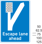 | 1. The route symbol may be varied 2. “ahead” may be varied to a distance, varied to an arrow pointing to the left or to the right, or omitted |
| 4 | Diagram 513.1A Risk of lorries overturning on adverse camber (with bend to the left) and maximum speed advised |  | 1. The symbol may be reversed when the bend is to the right 2. The numerals indicating the maximum speed advised may be varied as appropriate 3. The legend “Max speed 20” may be omitted |
PART 4Traffic signs for bridges and other structures
1. A warning, information or prohibition of a description in column 2 of an item in the sign table in this Part must be conveyed by a sign that is—
(a)of the colour and type; and
(b)complies with the requirements as to size,
provided for in the diagram in column 3 of the item.
2. In the case of the description at item 3, the warning is to be conveyed by both the triangular signs shown in the diagram in combination, and paragraph 1 applies to each of those signs.
3. A number in column 4 of the sign table in this Part indicates that the plate or structure warning marking provided for at that item number in the sign table in Part 5 is an associated plate or marking of the sign provided for in the sign table in this Part at the item number at which the relevant column 4 entry appears.
4. A provision of Part 7 mentioned (by reference to paragraph number) in column 5 of the sign table in this Part applies to the sign provided for at the item number in question.
5. A Schedule 2 General Direction mentioned (by reference to paragraph number) in column 6 of the sign table in this Part applies to the upright sign provided for at the item number in question.
Sign table — Schedule 2, Part 4
(1) Item | (2) Description | (3) Diagram | (4) Associated plate or structure warning marking (by reference to an item number in the Part 5 sign table) | (5) Applicable provisions in Part 7 | (6) Schedule 2 General Directions |
|---|---|---|---|---|---|
| 1 | Diagram 528.1 End of a bridge parapet, abutment wall, tunnel mouth or other obstruction adjacent to the carriageway |  | 9 | ||
| 2 | Diagram 530A Maximum headroom available at hazard, with height indicated in both metric and imperial units |  | 1, 3, 4 or 5 | 6, 12 | |
| 3 | Diagram 531.1A Maximum headroom available at arch bridge ahead |  | 2 or 5 | 6, 12 | 3 |
| 4 | Diagram 1024.1 Road marking indicating path to be taken by high vehicles under a low bridge or to avoid an overhanging structure |  | 11, 13 | ||
| 5 | Diagram 629.2A Vehicles exceeding height indicated prohibited with height indicated in both metric and imperial units |  | 4 | 1, 2, 6, 12 |
PART 5Associated plates and structure warning markings for signs in Part 4
1.—(1) A warning or information of a description specified in column 2 of an item in the sign table in this Part must be conveyed by a plate or structure warning marking which is of the size, colour and type provided for—
(a)in the diagram in column 3 of the item; or
(b)in that diagram varied in accordance with column 4.
2. A provision of Part 7 mentioned (by reference to paragraph number) in column 5 of the sign table applies to the structure warning marking provided for at the item number in question.
Sign table — Schedule 2, Part 5
(1) Item | (2) Description | (3) Diagram | (4) Variants | (5) Applicable provisions in Part 7 |
|---|---|---|---|---|
| 1 | Diagram 530.1 Reduced headroom over part of road due to overhanging building or structure |  | 1. The legend may include— (a) a distance, with or without an arrow pointing to the left or to the right; (b) an arrow pointing to the left or to the right 2. “building” may be varied to “buildings” or “structure” | |
| 2 | Diagram 531.2 High vehicles to use middle of road at arch bridge ahead, |  | The legend may include an arrow pointing to the left or to the right | |
| 3 | Diagram 532.4 Upper: Extent of headroom available at the side of and in the centre of a road at an arch bridge. Lower: Marking highlighting reduced headroom at an arch bridge. |  | 1. The position and number of chord markings in the upper part of the diagram may be varied as appropriate 2. The black and yellow marking may be omitted | 7, 9 |
| 4 | Diagram 530.2 Reduced headroom at a hazard (Alternative types) |  | 7, 9 | |
| 5 | Diagram 572 Distance ahead to hazard |  | 1. The distance may be varied to another distance 2. The legend may include an arrow pointing to the left or to the right |
PART 6Other warning signs
1. A warning of a description in column 2 of the sign table in this Part must be conveyed by a sign that is—
(a)of the colour and type; and
(b)complies with the requirements as to size,
provided for in the diagram in column 3 of the sign table at the item number for that description, or that diagram as varied in accordance with column 4.
2. In the case of the description at item 1, the warning is to be conveyed by the triangular sign shown in the diagram and, depending on the warning to be conveyed, both associated plates shown in the diagram, or only the upper one, and paragraph 1 applies to each of those signs.
3. A provision of Part 7 mentioned (by reference to paragraph number) in column 5 applies to the sign, or combination, at the item number in question.
4. A Schedule 2 General Direction mentioned (by reference to paragraph number) in column 6 applies to the sign at the item number in question.
Sign table — Schedule 2, Part 6
(1) Item | (2) Description | (3) Diagram | (4) Variants | (5) Applicable provisions in Part 7 | (6) Schedule 2 General Directions |
|---|---|---|---|---|---|
| 1 | Diagram 501 Junction ahead controlled by a “GIVE WAY” or “STOP” sign, wherean indication may be given that the junction iswith a dual carriageway road |  | 1. In the upper plate “GIVE WAY” is varied to “STOP” if the stop sign is placed at a junction ahead 2. The lower associated plate may be omitted 3. In the upper plate the distance may be varied | 6 | 4 |
| 2 | Diagram 560 Edge of carriageway or obstruction near that edge (Alternative types) |  | 1. The colour of the circular sign or the rectangular sign may be varied to white or amber 2. The surface of the rectangular sign may be curved | 4 | 5 |
| 3 | Diagram 515 Sharp deviation of route |  | 1. The chevrons may be reversed to point to the right 2. The number of chevrons may be varied 3. The corners of the sign may be rounded, with a radius not greater than 10 mm 4. The sign may be formed of a series of vertical flexible elements that need not have a horizontal cross section that is flat, provided that the elements extend to ground level to form the support for the sign and the support is coloured black 5. Where vertical flexible elements are used, the horizontal distance between the pointed ends of two consecutive chevrons may be increased by up to 4% of the dimensions shown in the diagram 6. Where vertical flexible elements are used, a yellow border may be added to the outside edge of the part of the sign that comprises the chevrons 7. Where vertical flexible elements are used, the sign may include a white arrow on a blue circular background as shown by the diagram in column 3 at item 1 of the sign table in Part 2 of Schedule 3. This is to be placed over the chevrons and any yellow border, and formed as part of those elements | 8, 9 | |
| 4 | Diagram 774 Location of a railway or tramway level crossing without gate or barrier |  | |||
| 5 | Diagram 781 Load gauge giving audible warning to drivers where vehicles exceed safe height under electrified overhead cables | 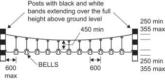 | 1. The number of bells may be increased or decreased according to the width of the road over which the sign is placed 2. The bells may be of any colour, provided each bell is of the same colour | 10 | |
| 6 | Diagrams 789, 789.1, 789.2 Countdown markers to railway or tramway level crossing |  | Each sign may be reversed |
PART 7Provisions applicable to signs
1. Section 36 of the 1988 Act applies to the sign.
2. The sign is specified for the purposes of column 5 of the entry in Schedule 2 to the Road Traffic Offenders Act 1988(54) relating to offences under section 36 of the 1988 Act.
3. If the sign is displayed on a variable message sign and displays its aspects by means of light-emitting characters or symbols, the legend “SLOW DOWN” may be displayed beneath the sign (and any associated plates) in characters having a height of not less than one quarter of the height of the displayed sign.
4. The sign must be illuminated by means of retroreflecting material.
5. The safe height shown on the first associated plate must be between 1 foot 3 inches and 2 feet (380 mm to 600 mm) less than the height of the lowest part of the overhead wire, of which the sign gives warning, over the highest part of the surface of the carriageway beneath that wire.
6.—(1) Subject to sub paragraph (2), where the sign is placed on a road within 50 metres of any lamp which forms part of a system of street-lighting, the illumination requirements for the sign are—
(a)where that system of street-lighting is illuminated throughout the hours of darkness, the sign must be illuminated by internal or external lighting for so long as that system is illuminated and may also be reflectorised; or
(b)where that system of street-lighting is not illuminated throughout the hours of darkness—
(i)the sign must be illuminated by internal or external lighting for so long as that system is illuminated and must also be reflectorised; or
(ii)the sign must be illuminated throughout the hours of darkness by internal or external lighting and may also be reflectorised.
(2) Sub-paragraph (1) does not apply to a sign where the road is subject to a speed limit of 20 mph.
(3) The exception in sub-paragraph (2) does not apply to a sign provided for at item 2 or 5 of the Part 4 sign table mounted on a bridge or other structure and, consequently, sub-paragraph (1) applies to such a sign.
7. The structure warning marking may be left unlit, or be illuminated either by means of internal or external lighting or by means of retroreflecting material.
8. Paragraph 6 applies to that part of the sign, if any, which is the white arrow on a blue circular background.
9. Where those parts of the sign coloured yellow, if any, are retroreflective, they may also be fluorescent.
10. The sign must not be illuminated.
11. The road marking must be reflectorised.
12. The sign may have different numerals to those shown in the diagram.
13. The arrow in the road marking may indicate a path to the left instead of to the right.
PART 8The Schedule 2 General Directions
1. The triangular sign must not be placed unless placed with a plate showing the applicable first plate legend indicated in column 4 of the sign table in Part 2 at the item number in question.
2. The sign may be fitted to the rear of a road maintenance vehicle.
3. The two triangular signs must be placed together (with or without an associated plate).
4. The triangular sign must be placed with its upper associated plate (whether or not the lower plate is also included).
5.—(1) The sign (“an edge of carriageway sign”) must be placed so that the top of the sign is not less than 550 mm nor more than 1000 mm above the surface of the adjacent carriageway.
(2) Where an edge of carriageway sign is mounted on a post specifically provided for the purpose that part of the post which extends above ground level may be—
(a)of any single colour; or
(b)coloured black and white in alternate horizontal bands, each band being not less than 225 mm or more than 350 mm deep.
(3) An edge of carriageway sign must be erected to display—
(a)the colour red on the left hand edge of the carriageway as viewed by the drivers of approaching vehicles; and
(b)the colour white on the right hand edge of the carriageway when so viewed, unless the edge is the edge of the carriageway of a dual carriageway road or a one-way road when the colour amber must be displayed.
Regulation 3, Direction 3
SCHEDULE 3Upright signs that indicate regulatory requirements for moving traffic
PART 1Provisions applicable to Parts 2, 3 and 4
1. The requirement, restriction or prohibition of a description in column 2 of the sign table in Part 2 must be conveyed by a circular sign of—
(a)the colour and type provided for a sign in the diagram in column 3; and
(b)the size provided for in column 4 of the table.
2. In the case of the description at item 25, the prohibition is to be conveyed by both the circular signs shown in the diagram in combination, and paragraph 1 applies to each of those signs.
3. A warning, information, requirement, restriction or prohibition of a description mentioned in Part 3 must be conveyed by a plate (a “Part 3 plate”) which—
(a)has the legend for conveying that warning or information written in a manner which complies with the requirements as to size for a plate provided for in the diagram above the sign table in Part 2; and
(b)complies with the requirements as to colour and type in that diagram.
4. A Part 3 plate containing a legend referred to in column 5 (by reference to a paragraph number in Part 3) of the sign table in Part 2 is an associated plate of the circular sign provided for in the Part 2 sign table at the item number at which the relevant column 5 entry appears.
5. A provision of Part 4 mentioned (by reference to paragraph number) in column 6 of the sign table in Part 2 applies to the circular sign at the item number in question.
6. A Schedule 3 General Direction mentioned (by reference to paragraph number) in column 7 of the sign table in Part 2 applies to the circular sign at the item number in question.
PART 2Circular signs and supplementary plates including regulatory requirements

Sign table — Schedule 3, Part 2
(1) Item | (2) Description | (3) Diagram | (4) Sign diameter | (5) Associated plate legend (by reference to an item number in the Part 3 sign table) | (6) Applicable provisions in Part 4 | (7) Schedule 3 General Directions |
|---|---|---|---|---|---|---|
| 1 | Diagram 606 Vehicular traffic must proceed in the direction indicated by the arrow (Alternative types) |  | 270, 300, 450, 600, 750, 900, 1200, 1500 | 1, 2 or 3 | 1, 2, 4 | 1, 2 |
| 2 | Diagram 609 Vehicular traffic must turn ahead in the direction indicated by the arrow (Alternative types) |  | 450, 600, 750, 900, 1200 | 1, 2 or 3 | 1, 2, 4 | 1 |
| 3 | Diagram 610 Vehicular traffic must comply with the requirements described in paragraph 3 of Part 4 (Alternative types) |  | 270, 300, 450, 600, 750, 900, 1200, 1500 | 2 | 1, 2, 3, 4 | 2 |
| 4 | Diagram 642 No stopping on main carriageway |  | 300, 450, 600, 750, 900, 1200 | 4 or 5 | 2, 4 | 1 |
| 5 | Diagram 632 No overtaking |  | 600, 750, 900, 1200 | 4, 5, 6 or 7 | 4 | 1 |
| 6 | Diagram 614 No U-turns for vehicular traffic |  | 270, 300, 450, 600, 750, 900, 1200 | 4 or 5 | 2, 4 | 1, 2 |
| 7 | Diagram 612 No right turn for vehicular traffic |  | 270, 300, 450, 600, 750, 900, 1200 | 3, 8, or both 3 and 8 | 2, 4 | 1, 2 |
| 8 | Diagram 613 No left turn for vehicular traffic |  | 270, 300, 450, 600, 750, 900, 1200 | 3, 8, or both 3 and 8 | 2, 4 | 1, 2 |
| 9 | Diagram 615 Priority must be given to vehicles from the opposite direction |  | 600, 750, 900, 1200 | 5, 9 or 10 | 1, 4 | 3 |
| 10 | Diagram 616 No entry for vehicular traffic |  | 270, 300, 450, 600, 750, 900, 1200 | 11 | 2, 4 | 1, 2 |
| 11 | Diagram 617 All vehicles prohibited except non-mechanically propelled vehicles pushed by pedestrians |  | 450, 600, 750, 900, 1200 | 12, 13 or 14; 8 and 14; 14 and 15; or 8, 14 and 15 | 4 (with plate legend 14) or 5 (with plate legend 12 or 13) | 1, 3 |
| 12 | Diagram 619 Motor vehicles prohibited |  | 450, 600, 750, 900, 1200 | 8, 15, or both 8 and 15 | 4 | 1 |
| 13 | Diagram 622.1A Goods vehicles exceeding the maximum gross weight indicated prohibited |  | 450, 600, 750, 900, 1200, 1500 | 6, 8, 15, or both 8 and 15 | 4, 6 | 1 |
| 14 | Diagram 622.2 End of prohibition of goods vehicles indicated by the sign provided for at item 13 |  | 450, 600, 750, 900 | 4 | 1 | |
| 15 | Diagram 622.4 Articulated or track laying vehicles prohibited (Alternative types) |  | 600, 750, 900 | 6 | 4 | 1 |
| 16 | Diagram 622.8 Vehicles carrying explosives prohibited |  | 450, 600, 750, 900, 1200 | 16 A second plate with a legend from 8 or 15, or both 8 and 15, may be added | 4 | 1, 3 |
| 17 | Diagram 952 Buses prohibited |  | 450, 600, 750, 900, 1200 | 8, 15, or both 8 and 15 | 4 | 1 |
| 18 | Diagram 619.1 Motor vehicles except solo motor cycles prohibited |  | 450, 600, 750, 900, 1200 | 8, 15, or both 8 and 15 | 4 | 1 |
| 19 | Diagram 622.7 Towed caravans prohibited |  | 450, 600, 750, 900, 1200 | 8, 15, or both 8 and 15 | 4 | 1 |
| 20 | Diagram 619.2 Solo motor cycles prohibited |  | 450, 600, 750, 900, 1200 | 8, 15, or both 8 and 15 | 4 | 1 |
| 21 | Diagram 951 Riding of pedal cycles prohibited |  | 150, 270, 300, 450, 600 | 4 (but only sub-paragraph (5)) | 1, 2 | |
| 22 | Diagram 625.1 Pedestrians prohibited |  | 150, 300, 450, 600 | 5 | 1 | |
| 23 | Diagram 622.5 Horse-drawn vehicles prohibited |  | 150, 300, 450, 600 | 8, 15, or both 8 and 15 | 5 | 1 |
| 24 | Diagram 622.6 Ridden or accompanied horses prohibited |  | 150, 300, 450, 600 | 8, 15, or both 8 and 15 | 5 | 1 |
| 25 | Diagram 629.1 Vehicles or combinations of vehicles exceeding the length indicated prohibited |  | 600, 750, 900 | 6, 8, 15, or both 8 and 15 | 4, 6 | 1, 4 |
| 26 | Diagram 629A Vehicles exceeding the width indicated prohibited in both metric and imperial units |  | 750, 900, 1200 | 6, 8, 15 or both 8 and 15 | 4, 6 | 1 |
| 27 | Diagram 629.2A Vehicles exceeding height indicated in metric and imperial units prohibited other than where the sign is placed— (a) on a road which passes under or through a bridge, tunnel or other structure which limits the height of vehicles using that road; or (b) on any such bridge, tunnel or other structure |  | 750, 900, 1200, 1500 | 4, 6 | 1 | |
| 28 | Diagram 955 Route for use by pedal cycles only |  | 100, 150, 270, 300, 450, 600 | 4 (but only sub-paragraph (5)) | 1, 2 | |
| 29 | Diagram 956 Route for use by pedal cycles and pedestrians only |  | 100, 150, 270, 300, 450, 600 | 4 (but only sub-paragraph (5)) | 1, 2 | |
| 30 | Diagram 956.1 Route for use by pedal cycles, horses and pedestrians only |  | 100, 150, 270, 300, 450, 600, 750 | 4 (but only sub-paragraph (5)) | 1, 2 | |
| 31 | Diagram 956.2 Route for use by pedal cycles, horse-drawn vehicles and pedestrians only |  | 100, 150, 270, 300, 450, 600, 750 | 4 (but only sub-paragraph (5)) | 1, 2 | |
| 32 | Diagram 957 Route comprising two ways for use by pedal cycles only and by pedestrians only, with those ways separated by the marking provided for at item 7 or 8 of the table in Part 6 of Schedule 9, or by physical means, (Alternative types) |  | 100, 150, 270, 300, 450, 600 | 4 (but only sub-paragraph (5)) | 1, 2 | |
| 33 | Diagram 953 Route for use by buses, pedal cycles and taxis only (Alternative types) |  | 450, 600, 750, 900 | 8, 17, or both 8 and 17 | 1, 4, 7, 8 | 1 |
| 34 | Diagram 953A Route for use by buses, pedal cycles and solo motor cycles only (Alternative types) |  | 450, 600, 750, 900 | 8, 17 or both | 1, 4 | 1 |
| 35 | Diagram 953B Route for use by buses, pedal cycles, solo motor cycles and taxis only (Alternative types) |  | 600, 750, 900, 1200 | 8, 17 or both | 1, 4 | 1 |
| 36 | Diagram 953.1 Route for use by tramcars only |  | 450, 600, 750, 900 | 8, 17, or both | 1, 4 | 1 |
| 37 | Diagram 953.1 (variant) Route for use by tramcars and buses only (Alternative types) |  | 450, 600, 750, 900 | 8, 17, or both | 1, 4 | 1 |
| 38 | Diagram 953.1A Route for use by tramcars, buses and pedal cycles only (Alternative types) |  | 600, 750, 900, 1200 | 8, 17, or both | 1, 4 | 1 |
| 39 | Diagram 953.1B Route for use by tramcars, buses, pedal cycles and taxis only (Alternative types) |  | 600, 750, 900, 1200 | 8, 17, or both | 1, 4 | 1 |
| 40 | Diagram 953.1C Route for use by tramcars, buses, pedal cycles, solo motor cycles and taxis only (Alternative types) |  | 600, 750, 900, 1200 | 8, 17, or both | 1, 4, 7 | 1 |
PART 3Legends for plates associated with circular signs
1. “One way”.
2. “Dual carriageway”.
3.—(1) Subject to sub‑paragraphs (2), (3) and (4), “Except” and any of, or a combination of, the following:
(a)“buses”;
(b)“local buses”;
(c)“taxis”;
(d)“cycles”;
(e)“authorised vehicles”;
(2) “buses” and “local buses” must not be used together.
(3) “and” or “&” must be inserted before the last legend where more than one is used.
(4) “Except” must be varied to “except” when preceded by the legend described in paragraph 8.
4. “For” and a distance.
5. “End”.
6. “Ice” or “Snowdrifts”.
7. “Ice for” or “Snowdrifts for”, and a distance.
8. A time period.
9. “Give way to oncoming vehicles”.
10. “Give way to oncoming vehicles for” and a distance.
11. “Except” and “trams”, “buses”, “local buses”, “cycles”, “buses and cycles” or “local buses and cycles”; “and” may be varied to “&”.
12. “Play Street except for access”.
13. “Play Street” and a time period and “except for access”.
14. “No vehicles”.
15.—(1) Subject to sub‑paragraphs (2) and (3), “Except” and any of, or a combination of, the following—
(a)“buses” or “local buses”;
(b)“taxis”;
(c)the disabled badge holder symbol;
(d)“permit holder” or “permit holders”, and, where appropriate, a permit identifier;
(e)one of—
(i)“for access”;
(ii)“for loading”;
(iii)“for loading by” and the lorry symbol shown in the diagram at item 1 of the table in Part 2 of Schedule 8;
(iv)“for access to off-street premises”.
(2) “and” or “&” must be inserted before the last legend where more than one is used.
(3) “Except” must be varied to “except” when preceded by the legend described in paragraph 8 or 12.
16. “No explosives” or “No inflammables or explosives”.
17. “and authorised vehicles”.
PART 4Provisions applicable to signs in Part 2
1. Section 36 of the 1988 Act applies to the circular sign.
2. Where the sign is placed temporarily on a road by a constable or person acting under the instructions (whether general or specific) of the chief officer of police for the purposes of indicating a temporary statutory provision, the following modifications to the requirements apply—
(a)the diameter of the circular sign must be at least 200 mm; and
(b)the x-height of the lettering on a plate where the legend is either “One way” or “End”, if used, must be at least 20 mm.
3.—(1) Except as provided in sub-paragraphs (2) to (5), the requirement conveyed by the sign is that vehicular traffic passing the sign must keep to the left of the sign where the arrow is pointed downwards to the left, or to the right of the sign where the arrow is pointed downwards to the right.
(2) Sub-paragraph (3) applies on an occasion where a vehicle is being used for at least one of the purposes set out in sub-paragraph (4) and the observance of the requirement in sub-paragraph (1) would be likely to hinder the use of the vehicle for that purpose.
(3) The requirement conveyed is that the vehicle must not proceed beyond the sign in such a manner or at such a time as to be likely to endanger any person.
(4) The purposes are—
(a)fire and rescue authority;
(b)Scottish Fire and Rescue Service;
(c)ambulance;
(d)blood service;
(e)providing a response to an emergency at the request of an NHS ambulance service;
(f)bomb or explosive disposal;
(g)special forces
(h)police; and
(i)National Crime Agency.
(5) The requirement in sub-paragraph (1) does not apply to a tramcar or trolley vehicle.
4.—(1) Subject to sub-paragraphs (2) to (5), where the sign is placed on a road subject to a speed limit greater than 20 mph, and is within 50 metres of any lamp which forms part of a system of street-lighting, the illumination requirements for the sign are—
(a)where that system of street-lighting is illuminated throughout the hours of darkness, the sign must be illuminated by internal or external lighting for so long as that system is illuminated and may also be reflectorised; or
(b)where that system of street-lighting is not illuminated throughout the hours of darkness—
(i)the sign must be illuminated by internal or external lighting for so long as that system is illuminated and must also be reflectorised; or
(ii)the sign must be illuminated throughout the hours of darkness by internal or external lighting and may also be reflectorised.
(2) Sub-paragraph (1) only applies to the sign at item 4 of the Part 2 sign table when being used as a terminal sign.
(3) Sub-paragraph (1) does not apply to a sign mounted on a self-righting bollard.
(4) Sub-paragraph (1) does not apply to a sign placed temporarily to indicate road works or an obstruction.
(5) Where the sign is mounted on a bollard fitted with a means of internal lighting, the sign must be illuminated throughout the hours of darkness by that means.
5. The sign need not be illuminated.
6. The sign may have different numerals to those shown in the diagram.
7. The word “taxi” may be omitted.
8. The cycle symbol may be omitted.
PART 5The Schedule 3 General Directions
1.—(1) The sign must only be placed to indicate the effect of an Act, order, regulation, bylaw, resolution or notice which prohibits or restricts the use of the road by traffic.
(2) When the sign is placed to indicate the point at which a restriction, requirement or prohibition begins or ends, it must be placed as near as practicable to that point.
(3) Sub-paragraphs (1) and (2) do not apply to—
(a)a sign provided for at item 1 of the Part 2 sign table, when placed on the central island of a roundabout or in combination with a plate displaying the legend “Dual carriageway”; and
(b)a sign provided for at item 2 of the Part 2 sign table (either without an associated plate or with a plate with the legend “Dual carriageway”), when placed on a road approaching its junction with a dual carriageway road.
2. Where the sign is mounted on a bollard—
(a)the bollard must—
(i)be illuminated by means of internal lighting; and
(ii)conform to British Standard BS EN 12899-2:2007(55); or
(b)in the case of a self-righting bollard, the bollard—
(i)must be illuminated by the use of retroreflecting material; and
(ii)conform to British Standard BS 8442:2015(56).
3. The sign must not be placed unless accompanied by its associated plate.
4. The two signs provided for must be placed together.
Regulation 3, Direction 3
SCHEDULE 4Upright signs that control waiting, loading and parking along a road
PART 1Blank panel diagram
PART 2On-street parking control signs
Yellow panel signs
1.—(1) A restriction or prohibition of a description in column 2 of the sign table in Part 3 must be conveyed by a sign which complies with paragraphs 2 to 7.
2. The sign must have a yellow background and black border as shown in blank diagram 1 in Part 1.
3.—(1) The sign must include a symbol of the size, colour and type shown in column 3 of the Part 3 sign table for the description in question.
(2) In the case of item 3, the sign must have the circular symbol shown in column 3 together with—
(a)the lorry symbol shown;
(b)the bus symbol shown; or
(c)both,
and each symbol included must be of the size, colour and type provided for in column 3 of item 3.
(3) The numeral forming part of the lorry symbol shown in the diagram may be varied to another numeral.
4. A sign provided for in the Part 3 sign table must include the legend or legends provided for in column 4 for the description in question.
5. A legend may be varied in accordance with an entry in column 5 (if any).
6. The legend must be of a height provided for in column 6 (by reference to x-height).
7. A sign must include an arrow pointing to the left or to the right where indicating the beginning of, or a change in, a restriction or prohibition.
White panel signs
8. A restriction, prohibition or information of a description in column 2 of the sign table in Part 4 must be conveyed by a sign which complies with paragraphs 9 to 18.
9. The sign must have a white background and black border as shown in blank diagram 2 in Part 1.
10.—(1) The sign must have a symbol of the size, colour and type shown in column 3 of the sign table in Part 4 for the description in question.
(2) Sub-paragraph (1) does not apply in relation to the description at item 1 of that table.
(3) The symbol provided for at item 5 may be reversed.
(4) For the purpose of conveying the description at item 6 or 7, the symbol shown at item 3 or 4 may be used instead of the symbol shown at item 6 or 7.
(5) Sub-paragraph (4) does not apply where the sign, in accordance with paragraph 15, includes the motor cycle or bus symbol shown at item 1 and 3 respectively of the Part 5 sign table.
11. A sign provided for at item 1, 5, 6, 7, or 8 of the Part 4 sign table must have the legend provided for in column 4 of the item.
12. A legend provided for at item 5, 6 or 7 of the Part 4 sign table may be varied in accordance with column 5 of the item.
13. A sign provided for at item 2, 3 or 4 of the Part 4 sign table may include a legend provided for in column 5 of the item.
14. A legend provided for in the Part 4 sign table must have an x-height provided for in column 6.
15. Where an item in the Part 4 sign table (“the Part 4 item”) shows numbers in column 7, those numbers—
(a)refer to items in the Part 5 sign table (“the Part 5 items”); and
(b)signify that a sign which includes the symbol shown in column 3 of the Part 4 item may also include a symbol shown in column 3 of one of the Part 5 items to convey the description in column 2 of that Part 5 item.
16.—(1) A symbol included in accordance with paragraph 15 must be of the size, colour and type provided for in relation to that symbol at the appropriate column 2 entry in the Part 5 sign table.
(2) If the symbol shown in column 3 of item 4, 5, 6, 7 or 8 of the Part 5 table is included in a sign, a legend in column 4 at that item must also be included.
(3) The symbol shown at item 1, 2 or 6 of the Part 5 table may be reversed.
(4) In the case of item 8 of the Part 5 table, the symbol may be varied to correspond with the design on the applicable approved voucher (provided the size remains as provided for in column 2).
17. A sign must include an arrow pointing to the left or to the right where indicating the beginning of, or a change in, a restriction or prohibition.
18.—(1) A sign may convey any two of the descriptions in column 2 in the Part 4 sign table (except the description at items 1 and 8), with “or” used to separate the legends applicable to the two descriptions.
(2) Where a sign conveys two descriptions in accordance with sub-paragraph (1), if the symbol applicable to those descriptions is the same, only one symbol need be included in the sign.
Signs consisting of multiple panels
19.—(1) This paragraph applies to all signs provided for in the sign tables in Parts 3, 4 and 5 except those for conveying a description in column 2 at—
(a)items 5 to 10 of the sign table in Part 3; and
(b)item 8 of the sign table in Part 4.
(2) A panel that would otherwise be a single sign in accordance with this Schedule may instead form part of a sign made up of at least two panels where each of the panels would otherwise be a single sign in accordance with this Schedule.
(3) The reference to a panel in sub-paragraph (2) is to the panel shown in blank diagram 1 or 2 in Part 1.
(4) This paragraph applies to a sign whether or not panels are included in accordance with paragraph 20 or 21.
20.—(1) This paragraph applies in relation to a sign provided for at item 2, 3, 4, 5, 6 or 7 of the Part 4 sign table.
(2) The sign may be divided into panels with a white background of the type shown in blank diagram 2 in Part 1 with any symbol or legend forming part of that sign being placed in any of those panels.
(3) This paragraph applies to a sign whether or not other panels are included in accordance with paragraph 19 or 21.
21.—(1) This paragraph applies to a sign which includes the symbol provided for at item 8 of the Part 5 sign table.
(2) Information on the voucher parking scheme may be shown on a separate panel with a white background of the type shown in blank diagram 2 in Part 1.
(3) This paragraph applies to a sign whether or not other panels are included in accordance with paragraph 19 or 20.
Provisions applying where the sign is made up of more than one panel
22. When, in accordance with paragraph 19, 20 or 21, two or more panels are used, there must be a single black line separating adjoining panels.
23.—(1) Panels included in a sign may be placed in any vertical or horizontal combination, and need not be aligned vertically or horizontally.
(2) Sub-paragraph (1) is subject to sub-paragraphs (3) to (7).
(3) No more than two panels may be placed horizontally.
(4) Where panels are placed vertically to form a column they must be of the same width.
(5) No white panel may be placed above a yellow panel which is in the same column.
(6) Any white panels about loading must be above any white panels about parking places which are in the same column.
(7) Where a single panel is placed above or below two panels placed side by side, that single panel must be placed centrally in relation to the other two panels.
Height of legends to be proportionate
24.—(1) This paragraph applies whether or not the sign consists of a single panel or more than one panel.
(2) The x-height of a legend used on a sign provided for in this Schedule must be in proportion to the size of any symbol on the sign.
(3) Where a sign contains more than one legend, the x height must be the same for each legend.
(4) Sub-paragraph (3) does not apply to the legends provided for at item 7 or 10 in the Part 3 sign table.
Illumination
25.—(1) A sign provided for in this Schedule need not be illuminated.
(2) Paragraph (1) does not apply to a sign containing the symbol and legend provided for at item 2, 9 or 10 of the Part 3 sign table.
PART 3Symbols and legends used in combination with a yellow panel
Sign table — Schedule 4, Part 3
(1) Item | (2) Description | (3) Symbol | (4) Legend | (5) Variant of legend | (6) Legend height (by reference to x-height) |
|---|---|---|---|---|---|
| 1 | Waiting prohibited for a time that is not continuous throughout the year |  | A time period | The legend may include either or both of— (a) “No waiting”; and (b) “except” followed by one or more of “taxis”, “ambulances”, “police vehicles”, and where more than one exception is provided for “and” or “&” must precede the final exception | Not less than 15 mm and not more than 40 mm |
| 2 | Stopping prohibited |  | 1. “No stopping”; and 2. “except” followed by— (a) “buses”; (b) “local buses”; or (c) one or more of “taxis”, “ambulances”, “police vehicles”, and where more than one exception is provided for “and” or “&” must precede the final exception | 1. The legend may include a time period 2. The legend may include “taxis” with a time period 3. The legend may include “BUS STAND” provided it is displayed above “No Stopping” and used in combination with “except buses” or “except local buses” | Not less than 15 mm and not more than 40 mm |
| 3 | Waiting of goods vehicles over the maximum gross weight shown or buses (or both) prohibited The lorry symbols are alternative types The bus symbols are alternative types | 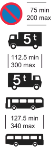 | A time period | Not less than 15 mm and not more than 40 mm | |
| 4 | Waiting prohibited in a Pedestrian Zone or a Restricted Parking Zone |  | 1. “Pedestrian Zone” or “Restricted Parking Zone”; and 2. A time period | 25 mm | |
| 5 | Waiting prohibited on a verge or on a footway |  | “At any time on” followed by “verge or footway”, “footway” or “verge” | Not less than 20 mm and not more than 40 mm | |
| 6 | Stopping prohibited on a verge or on a footway |  | “At any time on” followed by “verge or footway”, “footway” or “verge” | Not less than 20 mm and not more than 40 mm | |
| 7 | Entrance to a designated off-road loading area |  | 1. “Loading area”; 2. “Except by permitted vehicles”; and 3. A time period | 1. 50 mm for “Loading area” 2. 40 mm for “Except by permitted vehicles” 3. 40 mm for the time period | |
| 8 | Waiting prohibited in a designated off-road loading area |  | 1. “Except by permitted vehicles”; and 2. A time period | 40 mm | |
| 9 | Stopping prohibited in a lay-by except in emergency |  | “No stopping except in emergency” | 37.5 mm or 50 mm | |
| 10 | Stopping prohibited on entrance markings |  | 1. “No stopping”; and 2. “on entrance markings” | A time period may be included | 1. 50 mm for “No stopping” 2. 40 mm for “on entrance markings” 3. 40 mm for any time period |
PART 4Symbols and legends used in combination with a white panel
Sign table — Schedule 4, Part 4
(1) Item | (2) Description | (3) Symbol | (4) Required legends | (5) Variants to column 4 legends, or legends that may be included | (6) Legend height (by reference to x-height) | (7) Applicable Part 5 item |
|---|---|---|---|---|---|---|
| 1 | Loading prohibited | 1. “No loading” 2. A time period | Not less than 15 mm and not more than 40 mm | |||
| 2 | Parking place |  | 1. A time period may be included 2. A permitted parking expression may be included 3. A type or types of user may be included and, where the user is a type of permit holder, a permit identifier may be included 4. A legend provided for at 3 above may be varied by the addition of “only” or “only at all times” 5. The name of the traffic authority may be included 6. A parking place identifier or a zone identifier may be included | Not less than 15 mm and not more than 40 mm | 1, 2, 3, 4, 5, 6, 7, 8 | |
| 3 | Parking place where vehicles may be parked partially on the verge or footway (Alternative types) |  | 1. A time period may be included 2. A permitted parking expression may be included 3. A type or types of user may be included and, where the user is a type of permit holder, a permit identifier may be included 4. A legend provided for at 3. above may be varied by the addition of “only” or “only at all times” 5. The name of the traffic authority may be included in the sign 6. A parking place identifier or a zone identifier may be included in the sign | Not less than 15 mm and not more than 40 mm | 2, 4, 5, 7, 8 | |
| 4 | Parking place where vehicles may be parked wholly on the verge or footway (Alternative types) |  | 1. A time period may be included 2. A permitted parking expression may be included 3. A type or types of user may be included and, where the user is a type of permit holder, a permit identifier may be included 4. A legend provided for at 3 above may be varied by the addition of “only” or “only at all times” 5. The name of the traffic authority may be included 6. A parking place identifier or a zone identifier may be included | Not less than 15 mm and not more than 40 mm | 2, 4, 5, 7, 8 | |
| 5 | Parking place reserved for loading and unloading |  | “Loading only” | 1. “Loading only” may be varied to “Loading”, “Goods vehicles loading” or “Goods vehicles loading only” 2. The legend may be varied to include— (a) a time period; (b) a permitted parking expression; or (c) both 3. The name of the traffic authority may be included 4. A parking place identifier may be included | Not less than 15 mm and not more than 40 mm | |
| 6 | Parking not subject to payment conditions | | “Free” | The permitted variants at item 2 apply | Not less than 15 mm and not more than 40 mm | 1, 2, 3, 4, 5, 6, 7, 8 |
| 7 | Parking subject to payment conditions | | “Pay at machine” | 1. The permitted variants at item 2 apply 2. “Pay at machine” may be varied to any of the following or any appropriate combination of the following— (a) “Pay here at machine” (b) “Pay at machine across road” (c) “Pay at machine opposite” (d) “Pay at machine” and a location (e) “Pay at” and a description of the ticket machine in any coloured letters (f) “Display ticket” (g) “Pay by phone” and a telephone number and “or text” and a text number and “quoting location” and a location number (h) “Pay by phone” and a telephone number and “quoting location” and a location number (i) “Pay by text” and a text number and “quoting location” and a location number (j) Disc Zone”, “Disc parking”, “Ticket Zone” or “Ticket parking” 3. “Pay” in the legend “Pay at machine”, or in any of the legends referred to in entry 2, may be varied to “For longer stay pay” 4. Where the legend refers to a ticket machine, the legend may include an arrow pointing horizontally to the left or to the right, or one arrow pointing to the left and one to the right, to indicate the location of the machine or machines | Not less than 15 mm and not more than 40 mm | 1, 2, 3, 4, 5, 6, 7, 8 |
| 8 | Drivers must obtain and display parking tickets | | “Have you paid and displayed?” | Not less than 15 mm and not more than 40 mm |
PART 5Symbols to be used with Part 4 symbols on a white panel
Sign table — Schedule 4, Part 5
(1) Item | (2) Description | (3) Symbol | (4) Legend | (5) Legend height (by reference to x-height) | |
|---|---|---|---|---|---|
| 1 | Parking place reserved for solo motor cycles |  | |||
| 2 | Parking place reserved for motor cars |  | |||
| 3 | Parking place reserved for buses (Alternative types) | 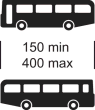 | |||
| 4 | Parking place reserved for disabled badge holders |  | 1. “Disabled badge holders”; 2. “Disabled badge holders only”; 3. “Disabled badge holders only at all times”; 4. “Disabled badge holder” and a permit identifier; or 5. “Disabled badge holder only” and a permit identifier | Not less than 15 mm and not more than 40 mm | |
| 5 | Parking place reserved for car club permit holders |  | “Car club permit holders only” | Not less than 15 mm and not more than 40 mm | |
| 6 | Parking place reserved for the recharging of electric solo motor cycles |  | 1. “Electric solo motor cycle recharging point only”; or 2. “Electric solo motor cycle recharging point” and “Permit holders only” with or without a permit identifier | Not less than 15 mm and not more than 40 mm | |
| 7 | Parking place reserved for the recharging of electric vehicles |  | 1. “Electric vehicle recharging point only”; or 2. “Electric vehicle recharging point” and “Permit holders only” with or without a permit identifier, | Not less than 15 mm and not more than 40 mm | |
| 8 | Parking place reserved for vehicles displaying an appropriate voucher |  | 1. “Voucher parking only”; 2. “Voucher parking and permits only”; 3. “Voucher parking and resident permits only”; 4. “Voucher parking and business permits only”; or 5. a legend provided for at 2, 3, or 4 with a permit identifier | Not less than 15 mm and not more than 40 mm | |
PART 6The Schedule 4 General Direction
1.—(1) The signs provided for in this Schedule must only be placed to indicate the effect of an Act, order, regulation, bylaw, resolution or notice which prohibits or restricts the use of the road by traffic.
(2) Sub-paragraph (1) does not apply to a sign which consists solely of the elements provided for in the Part 3 sign table at—
(a)item 2 (except where the taxi, ambulance or police vehicle legend in column 4 at paragraph 2(c) is included); or
(b)item 10.
Regulation 3, Direction 3
SCHEDULE 5Signs to indicate parking places and areas subject to parking controls
PART 1Parking place signs and plates
1. A sign for indicating a parking place (a “parking place sign”) must be square and of the size, colour and type shown in the upper part of the diagram above the sign table in this Part.
2. A restriction of a description in column 2 of items 2 to 6 of the sign table in this Part must be conveyed by a plate of the size, colour and type provided for in the diagram in column 3 at the item in question.
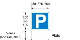
Sign table — Schedule 5, Part 1
(1) Item | (2) Description | (3) Plate | (1) Item | (2) Description | (3) Plate | |
|---|---|---|---|---|---|---|
| 1 | Parking place | 2 | Diagram 804.4 Parking place reserved for solo motor cycles |  | ||
| 3 | Diagram 804.2 Parking place reserved for motor cars |  | 4 | Diagram 804.3 Parking place reserved for motorised caravans or caravans drawn by motor vehicles |  | |
| 5 | Diagram 804.1 Parking place reserved for goods vehicles |  | 6 | Diagram 969 Parking place reserved for buses |  |
PART 2Entrance to a zone or area (other than a pedestrian, or a pedestrian and cycle, zone) where parking controls apply

3. The provisions as to size, colour and type in this Part apply to a sign for conveying information, a restriction or a prohibition of a description in column 2 of an item in the sign table in Part 3.
4. The sign must be of the shape shown in the diagram at the beginning of this Part with a white background and black lines as shown (except that the bottom panel may or must be omitted – see paragraph 5).
5. The upper panel must contain—
(a)the symbol or symbols shown in column 3 of the item; and
(b)a legend shown in column 4 of the item, with the height and placing of the legend complying with column 5.
6. The upper panel may be varied in accordance with column 6 of the item.
7. Where provided for in column 7 of the item, a legend specified at column 2, or column 2 when read with column 4, in the sign table in Part 4 may be included in the lower panel and, where no legend is included, the lower panel must be omitted.
8. A legend or symbol included in the lower panel must comply with the requirements as to size in column 3 of the item in the Part 4 sign table in which the legend or symbol is specified.
PART 3The upper panel and provision on inclusion of the lower panel
Sign table — Schedule 5, Part 3
(1) Item | (2) Description | (3) Symbol | (4) Legend | (5) Height and location of legend | (6) Permitted variants | (7) Inclusion of a lower panel |
|---|---|---|---|---|---|---|
| 1 | Entrance to a controlled parking zone applying to all vehicles |  | “Controlled ZONE” | x-height: 1. 60 mm or 80 mm for “Controlled” 2. 75 mm or 100 mm for “ZONE” Location: Above the symbol | 1. The name of the traffic authority may be added above any other legend 2. A zone identifier may be added— (a) where the identifier is a name, at the top of the panel (but below the name of the traffic authority if used); (b) where the identifier is a code, to the right of the legend in column 4 3. The legend “No loading” may be added below the symbol if that legend is of the same size as the legend at column 4 4. “Controlled” may be varied to “Meter”, “Disc”, “Ticket”, “Disc and Meter”, “Disc and Ticket” or “Pay and Display | A lower panel may be included showing a legend specified in the Part 4 sign table at item 1 |
| 2 | Entrance to a restricted parking zone |  | “Restricted parking ZONE” | x-height: 1. 60 mm or 80 mm for “Restricted parking” 2. 75 mm or 100 mm for “ZONE” Location: Above the symbol | 1. The name of the traffic authority may be added above any other legend 2. A zone identifier may be added— (a) where the identifier is a name, at the top of the panel (but below the name of the traffic authority if used); (b) where the identifier is a code, to the right of “ZONE” 3. The legend “No loading” may be added below the symbol if that legend is of the same size as “Restricted parking” | A lower panel may be included showing a legend specified in the Part 4 sign table at item 2 |
| 3 | Entrance to a voucher parking zone |  | “Voucher parking ZONE” | x-height: 1. 60 mm or 80 mm for “Voucher parking” 2. 75 mm or 100 mm for “ZONE” Location: Between the upper and lower symbol | 1. The legend “No loading” may be added below the lower symbol if that legend is of the same size as the legend at column 4 2. The name of the traffic authority may be added at the top of the panel 3. A zone identifier may be added— (a) where the identifier is a name, at the top of the panel (but below the name of the traffic authority if used). (b) where the identifier is a code, to the right of “ZONE” 4. The upper symbol may be varied to an appropriate symbol identifying the voucher parking area in question 5. “Voucher parking” may be varied to “Voucher parking and Meter” or “Voucher parking and Ticket” | A lower panel may be included showing a legend specified in the Part 4 sign table at item 1 |
| 4 | Entrance to a controlled parking zone applying to goods vehicles over the maximum gross weight shown or buses (or both) | 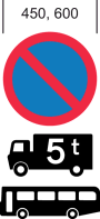 | “ZONE” | x-height: 75 mm or 100 mm for “ZONE” Location: Below the symbols | 1. The number on the lorry symbol may be varied 2. Either the lorry symbol or the bus symbol may be omitted 3. The name of the traffic authority may be added at the top of the panel | A lower panel may be included showing a legend specified in the Part 4 sign table at item 1 |
| 5 | Entrance to a permit parking area |  | One of—“Permit holders parking only past this point”; | x-height: 40 mm Location: Below the symbol | 1. A time period may be added 2. The name of the traffic authority may be added at the top of the panel 3. Permit identifiers may be added either to the right of the symbol or proximate to “permit holders” 4. “Permit holders parking only past this point” may be varied to “Resident permit holders parking only past this point”, “Permit holders parking only in” and a street name or “Resident permit holders parking only in” and a street name | A lower panel may be included showing the legend specified in the Part 4 sign table at item 3 |
| 6 | Entrance to a loading only area |  | “Loading only past this point” or “Goods vehicle loading only past this point” | x-height: 40 mm Location: Below the symbol | 1. A time period may be included after the legend 2. The name of the traffic authority may be added at the top of the panel | A lower panel must not be included |
| 7 | Entrance to an area where parking on the verge or footway is prohibited |  | The name of a zone, city, town, village, area or road | x-height: 50 mm Location: Above the symbol | 1. The symbol may be reversed 2. The legend may be omitted | A lower panel must be included showing the legend specified in the Part 4 sign table at item 4 |
PART 4Legends and symbols in the lower panel
Sign table — Schedule 5, Part 4
(1) Item | (2) Legend | (3) Height of legend or symbol | (4) Permitted variants |
|---|---|---|---|
| 1 | A time period | x-height: 37.5 or 50 mm | |
| 2 | A time period | x-height: 37.5 or 50 mm | 1. “Except in signed bay” instead of the time period at column 2 2. “except in signed bay” to follow the time period at column 2 3. “bays” may be used instead of “bay” |
| 3 | “Except in signed bay” | 1. Legend x-height: 40 mm 2. A height of 200 mm in respect of a symbol | 1. “Except” followed by either or both of the disabled badge holder symbol and the loading symbol (the symbol in column 3 of item 6 of the Part 3 sign table), to be followed by “in signed bay”. If both symbols are included “and” or “&” must be inserted between them 2. A time period may follow the column 2 legend or permitted variant 1 3. “bays” may be used instead of “bay” |
| 4 | “No motor vehicle parking on verge or footway except where signed” | x-height: 50 mm | 1. “motor vehicle” or “except where signed”, or both, may be omitted 2. “verge or footway” may be varied to “verge” or “footway” |
PART 5The Schedule 5 General Direction
1.—(1) The signs provided for in this Schedule must only be placed on or near a road to indicate the effect of an Act, order, regulation, bylaw, resolution or notice which prohibits or restricts the use of the road by traffic.
(2) This does not apply to a parking place sign provided for at paragraph 1 of Part 1 of this Schedule when placed without an associated plate.
Regulation 3, Direction 3
SCHEDULE 6Upright signs for red routes
PART 1Provisions applying to Part 2

1. An upright sign for conveying a restriction or prohibition applicable to a red route must comply with the requirements as to size, colour and type provided for in this Part.
2. The sign must consist of the top and middle panels of the sign shown in the diagram at the beginning of this Part and may also include the bottom panel shown if that is permitted under this Part.
3. The top panel may be varied so “RED ROUTE” appears on one line.
4. The middle panel may be varied to include—
(a)a time period;
(b)“except” followed by—
(i)“buses” or “local buses”;
(ii)“in signed bays” or “in signed bay”; or
(iii)one or more of “taxis”, “ambulances”, and “police vehicles”, and where more than one of those exceptions is provided for “and” or “&” must precede the final exception;
(c)“BUS STAND” if displayed above “No stopping” and in combination with “except buses” or “except local buses”.
5. If “except buses”, “except local buses”, “except in signed bays” or “except in signed bays” is included in the middle panel, the bottom panel as shown in the diagram at the beginning of this Part must not be included in the sign.
6. Unless paragraph 5 applies, the sign may include a bottom panel as shown in the diagram with, beneath “Except”, one or more of the symbols in column 3 of the sign table in Part 2 (for conveying an exception as described in column 2 for the symbol at the item number in question).
7. A symbol provided for at item 4,5, 6, 8, 9, 10 or 11 of the sign table must only be used in conjunction with another symbol as indicated in column 2.
8. The size of the symbol must comply with the requirements shown in column 3.
9. The bottom panel may also include a legend, to accompany the symbol, as described in column 4 of the sign table in Part 2.
10. The bottom panel may be varied in accordance with column 5 of the sign table in Part 2 for the item in question.
PART 2Symbols and legends used on a bottom panel
Sign table — Schedule 6, Part 2
(1) Item | (2) Description | (3) Symbol | (4) Additional legend | (5) Permitted variants |
|---|---|---|---|---|
| 1 | Parking place |  | 1. A time period may be added 2. A permitted parking expression may be added 3. A type or types of user may be added and, where the user is a type of permit holder, a permit identifier may be added | |
| 2 | Parking place where vehicles may be parked partially on the verge or footway (Alternative types) |  | 1. A time period may be added 2. A permitted parking expression may be added 3. A type or types of user may be added and, where the user is a type of permit holder, a permit identifier may be added | |
| 3 | Parking place where vehicles may be parked wholly on the verge or footway (Alternative types) | 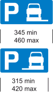 | 1. A time period may be added 2. A permitted parking expression may be added 3. A type or types of user may be added and, where the user is a type of permit holder, a permit identifier may be added | |
| 4 | Parking place reserved for solo motor cycles May only be used in conjunction with the symbol at item 1, 13 or 14 |  | ||
| 5 | Parking place reserved for motor cars May only be used in conjunction with the symbol at item 1, 2, 3, 13 or 14 |  | ||
| 6 | Parking place reserved for buses May only be used in conjunction with the symbol at item 1, 13 or 14 |  | ||
| 7 | Parking place reserved for disabled badge holders |  | 1. A time period may be added 2. A permitted parking expression may be added 3. “Permit holder” or “Permit holders” may be added and, in either case, any permit identifier as appropriate | |
| 8 | Parking place reserved for car club permit holders May only be used in conjunction with the symbol at item 1, 2, 3, 13 or 14 |  | “Car club permit holders only” | |
| 9 | Parking place reserved for the recharging of electric solo motor cycles May only be used in conjunction with the symbol at item 1, 13 or 14 |  | “Electric solo motor cycle recharging point only” | The legend may be varied to “Electric solo motor cycle recharging point” and “Permit holders only”, with or without a permit identifier |
| 10 | Parking place reserved for the recharging of electric vehicles May only be used in conjunction with the symbol at item 1, 2, 3, 13 or 14 |  | “Electric vehicle recharging point only” | The legend may be varied to “Electric vehicle recharging point” and “Permit holders only”, with or without a permit identifier |
| 11 | Parking place reserved for vehicles displaying an appropriate voucher May only be used in conjunction with the symbol at item 1, 2, 3, 13 or 14 |  | “Voucher parking” | 1. The voucher symbol may be varied to correspond with the design on the approved voucher within the size shown 2. The legend may be varied to “Voucher parking and permits only”, “Voucher parking and resident permits only” or “Voucher parking and business permits only” 3. The legend provided for at 2 above may be varied to include a permit identifier 4. An additional white panel may be added to the sign to show information on the voucher parking scheme |
| 12 | Parking place reserved for loading and unloading |  | “Loading” | 1. The legend may be varied to “Goods vehicles loading” 2. The legend may be varied to include— (a) a time period; or (b) a permitted parking expression, or both |
| 13 | Parking place not subject to payment conditions | | “Free” | 1. The permitted variants at item 1 2. The symbol may be varied to that at item 2 or 3, except when used in combination with the symbol at item 4 or 6 |
| 14 | Parking place subject to payment conditions | | “Pay at machine” | 1. The permitted variants at item 1 2. The symbol may be varied to that at item 2 or 3, except when used in combination with the symbol at item 4 or 6 3. “Pay at machine” may be varied to any of the following or any appropriate combination of the following— (a) “Pay by phone” (b) “Pay by text” (c) “Pay by phone or text” (d) “Disc Zone”, “Disc parking”, “Ticket Zone” or “Ticket parking” 4. “Pay” in the legend “Pay at machine”, or in any of the legends at entry 3, may be varied to “For longer stay pay” |
PART 3The Schedule 6 General Direction
1. The signs provided for in this Schedule must only be placed to indicate the effect of an Act, order, bylaw, resolution or notice which prohibits or restricts the use of the road by traffic.
Regulation 3, Direction 3
SCHEDULE 7Road markings and miscellaneous upright signs that indicate stopping, waiting, loading and parking controls
PART 1Provisions applying to Part 2
1. The information, requirement, restriction or prohibition of a description in column 2 of the sign table in Part 2 must be conveyed by a sign that is—
(a)of the colour and type; and
(b)complies with the requirements as to size,
shown in the diagram in column 3 of the table at the item in question, or that diagram as varied in accordance with column 4.
2. The signs provided for at items 5, 12, 13, 14, 15, 16 and 17 of the Part 2 sign table need not be illuminated.
PART 2Regulatory signs for stopping, waiting, loading and parking controls
Sign table — Schedule 7, Part 2
(1) Item | (2) Description | (3) Sign diagram | (4) Permitted variants |
|---|---|---|---|
| 1 | Diagram 664 End of controlled, voucher or restricted parking zone |  | |
| 2 | Diagram 666 End of controlled parking zone applying to goods vehicles over the maximum gross weight shown or buses (or both) |  | 1. The number on the lorry symbol may be varied 2. The lorry symbol or the bus symbol may be omitted |
| 3 | Diagram 664.1 End of permit parking area |  | |
| 4 | Diagram 664.2 End of loading only area |  | |
| 5 | Diagram 640.5 End of designated off-road loading area |  | |
| 6 | Diagram 646 No stopping during time periods indicated except for so long as may be necessary for the purpose of picking up or setting down passengers |  | 1. Days of the week may be varied 2. The time periods shown in the “am” and “pm” panels may be varied to any other periods |
| 7 | Diagram 647 End of the restriction on stopping indicated by the sign at item 6 |  | |
| 8 | Diagram 642.4 Stopping of vehicles prohibited at all times on a red route clearway (and conveying to drivers that this prohibition is not indicated by double red lines) | 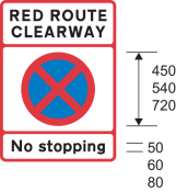 | |
| 9 | Diagram 642.5 End of prohibition on stopping indicated by the sign at item 8 |  | |
| 10 | Diagram 663.4 Reminder to drivers that parking on the verge or footway is prohibited (Alternative types) |  | |
| 11 | Diagram 664.3 End of area where parking on verge or footway is prohibited (Alternative types) |  | |
| 12 | Diagram 667 Vehicles may be parked partially on the verge or footway (Alternative types) |  | An arrow pointing to the left or to the right may be added |
| 13 | Diagram 668 Vehicles may be parked wholly on the verge or footway (Alternative types) | 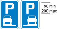 | An arrow pointing to the left or to the right may be added |
| 14 | Diagram 667.1 Vehicles may be parked partially on the verge or footway during the period indicated (Alternative types) |  | 1. An arrow pointing to the left or to the right may be added in the lower panel 2. “In marked bays” may be added to or substituted for the times shown in the lower panel 3. The time period may be varied to another time period |
| 15 | Diagram 668.1 Vehicles may be parked wholly on the verge or footway during the period indicated (Alternative types) | 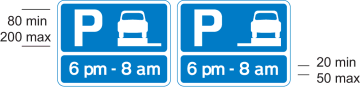 | 1. An arrow pointing to the left or to the right may be added in the lower panel 2. “In marked bays” may be added to or substituted for the times shown in the lower panel 3. The time period may be varied to another time period |
| 16 | Diagram 667.2 End of area where vehicles may be parked partially on the verge or footway (Alternative types) |  | |
| 17 | Diagram 668.2 End of area where vehicles may be parked wholly on the verge or footway (Alternative types) | 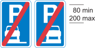 |
PART 3Provisions applying to road markings in Part 4
1. A restriction or prohibition of a description in column 2 of an item in the Part 4 sign table must be conveyed by road markings of the size, colour and type shown in—
(a)the diagram in column 3; or
(b)that diagram as varied in accordance with the paragraph in Part 5 whose number appears in column 4 of the item.
2.—(1) Where the road marking at item 9 is placed in a lay-by, studs may also be placed.
(2) The studs must incorporate—
(a)green reflectors;
(b)green retroreflecting material; or
(c)a light source that emits, during the hours of darkness, a steady green light,
or any combination.
(3) The studs must be placed in the gaps between the broken line that indicates the edge of the lay‑by to drivers of approaching vehicles.
(4) The external part of the stud that is visible when the stud is in place must be—
(a)green
(b)white;
(c)of a natural metallic finish;
(d)of another neutral colour; or
(e)clear,
or any combination (but see sub-paragraph (5) for an exception).
(5) The external part of a stud that is visible when the stud is in place temporarily during road works must be fluorescent green-yellow except to the extent—
(a)it consists of green reflectors or retroreflecting material; or
(b)it is necessary for it to be a different colour or clear in order for the stud to emit green light.
3. Section 36 of the 1988 Act applies to the markings at items—
(a)9; and
(b)10 where the marking is placed in the circumstances mentioned in paragraph 3 of Part 6.
PART 4Road markings for stopping, waiting, loading and parking controls
Sign table — Schedule 7, Part 4
(1) Item | (2) Description | (3) Diagram | (4) Variants in Part 5 |
|---|---|---|---|
| 1 | Diagram 1018.1 (a) Waiting of vehicles prohibited at all times or (b) stopping of vehicles in a lay-by prohibited except in emergency |  | 3 |
| 2 | Diagram 1017 Waiting of vehicles prohibited for a time that is not continuous throughout the year | 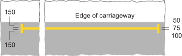 | 3 |
| 3 | Diagram 1020.1 Loading and unloading of vehicles prohibited at all times | 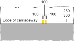 | 4 |
| 4 | Diagram 1019 Loading and unloading of vehicles prohibited for a time that is not continuous through the year |  | 4 |
| 5 | Diagram 1028.2 Area of carriageway reserved for taxis or, where the legend is varied as indicated in column 4, reserved for ambulances or police vehicles, where waiting by other vehicles is prohibited (Alternative types) |  | 6, 7, 10 |
| 6 | Diagram 1028.4 Alternative types of parking bay— (a) at the edge of the carriageway and situated wholly on either the carriageway or footway; or (b) in the centre of the carriageway or partly on the carriageway and partly on the footway |  | 1, 2, 5, 7, 10 |
| 7 | Diagram 1028.5 Area of carriageway reserved for taxis or, where the legend is varied as indicated in column (4), reserved for ambulances or police vehicles, where stopping by other vehicles is prohibited |  | 6, 7, 8, 10 |
| 8 | Diagram 1028.6 Parking bay for use by all vehicles or, where indicated by upright signs, by specified vehicles, and where at certain times, as indicated by upright signs, the bay is reserved for taxis, ambulances or police vehicles, where stopping by other vehicles is prohibited |  | 2, 5, 7, 8 |
| 9 | Diagram 1025.1 Clearway at which, as described in paragraph 1 of Part 6, vehicles must not stop (exceptions apply for buses and taxis) |  | 7, 9, 10, 11, 12, 13 |
| 10 | Diagram 1027.1 Part of the carriageway outside an entrance where, as described in paragraph 2 or 3 (as applicable) of Part 6, vehicles should, or must, not stop | 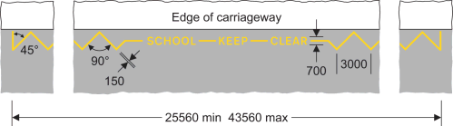 | 14, 15, 16 |
| 11 | Diagram 1018.2 Stopping of vehicles prohibited at all times |  | 3 |
| 12 | Diagram 1017.1 Stopping of vehicles prohibited for a time that is not continuous throughout the year | 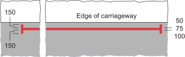 | 3 |
PART 5Required or permitted variants
1.—(1) ”DOCTOR” may be omitted.
(2) “DOCTOR” may be varied to: “BUSES”, “CAR CLUB”, “CYCLE HIRE”, “DISABLED”, “ELECTRIC VEHICLES”, “ELECTRIC VEHS”, “ELECTRIC MOTORCYCLES”, “ELECTRIC M/CYCLES”, “ELECTRIC M/Cs”, “LOADING”, “LARGE OR SLOW VEHICLES”, “PERMIT HOLDERS”, “SOLO MOTORCYCLES”, “SOLO M/CYCLES”, “SOLO M/CS”.
(3) “ONLY” may be added after “DOCTOR” (or after a word or phrase used pursuant to sub-paragraph (2)).
(4) Where the bay is reserved for an individual disabled badge holder, an alphanumeric identifier, with or without the word “ONLY” may be added after “DISABLED”.
2.—(1) When reserved for disabled badge holders at certain times (whether or not also reserved for other users)—
(a)the length of the bay must be at least 6600 mm; and
(b)the width of the bay must be at least 2700 mm (or 3000 mm when placed in the centre of the carriageway) except in a case where, on account of the nature of traffic using the road, the overall width of the carriageway is insufficient to accommodate a bay of that width.
(2) The marks and gaps forming the boundary of the bay may—
(a)vary in number and length; or
(b)be replaced by a continuous white line.
(3) The bay may be varied to contrast, in pattern or colour, from the surrounding parts of the road and any adjoining bays, in which case the marking may be omitted.
(4) The bay may be divided into individual spaces by—
(a)the application of a white line marking (either broken or continuous), with a minimum width of 50 mm; or
(b)contrasting pattern or colour.
(5) If the individual spaces are parallel to the edge of the carriageway, the length of each space must be not less than—
(a)6600 mm in the case of a space reserved for disabled badge holders; or
(b)4500 mm in any other case.
(6) If the individual spaces are not parallel to the edge of the carriageway—
(a)the length of the largest rectangle that could be accommodated wholly within the space in question must be not less than 4200 mm;
(b)the width of each space must be—
(i)not less than 3600 mm in the case of a space reserved for disabled badge holders; or
(ii)not less than 2000 mm in any other case, and
(c)the spaces may be inclined at any angle to the edge of the carriageway to form an overall parking bay in echelon pattern, the boundary of which, furthest from the edge of the carriageway, may be parallel to the carriageway.
3. The transverse mark at the end of the line may be omitted.
4. The marking may be continued down the vertical face of a kerb at the edge of the carriageway.
5. The marks forming the boundary of the bay and any legend must be coloured red when placed on a red route, but only where the bay is not available for parking or loading during part of, or all of, the times of operation of the red route.
6. ”TAXIS” may be varied to “AMBULANCES” or “POLICE”.
7. The transverse line may be omitted—
(a)from that part of the marking that is placed within a lay-by; or
(b)from that part of the bay which is delineated by a raised kerb.
8. Where the marking is placed on a red route, the continuous line must be substituted by the marking provided for at item 11 or 12 of the Part 4 sign table.
9. ”STOP” may be varied to “STAND”.
10. The legend may be repeated along the length of the marking as appropriate.
11. Where the marking is placed in part of a lay‑by, the continuous line may be used to delineate the clearway from that part of the lay‑by used by all vehicles.
12. The continuous line must be varied to red where placed along a red route and taxis are prohibited from stopping within the clearway.
13. The continuous line must be replaced by the marking provided for at item 11 or 12 of the Part 4 table where placed along a red route and taxis are permitted to stop within the clearway to pick up or set down passengers.
14. ”SCHOOL” may be varied to “CHILDREN” with the maximum length of the marking increased to 44545 mm in consequence.
15. ”SCHOOL” and the line between “SCHOOL” and “KEEP” may be omitted and the minimum length of the marking reduced to 25250 mm when used outside a fire, police or ambulance station, or a hospital.
16. The overall length of the marking may be varied within the specified limits by the addition or removal of an equal number of complete zig‑zag elements on each side of the legend.
PART 6The significance of particular road markings
Clearways (diagram 1025.1)
1.—(1) Subject to sub-paragraph (3) and paragraph 4, the road marking provided for at item 9 of the Part 4 sign table conveys the prohibition that a person driving a vehicle must not cause it to stop within the clearway—
(a)if the relevant upright sign placed in conjunction with the marking does not show a time period, at any time; or
(b)if the relevant upright sign shows a time period, during that period.
(2) For the purposes of this paragraph—
(a)“clearway” means an area of carriageway bounded by the continuous and broken straight lines provided for at item 9;
(b)“relevant upright sign” means an upright sign which includes a stopping prohibited symbol and indicates that stopping by vehicles other than buses or local buses is prohibited, or prohibited during the period indicated; and
(c)a vehicle is taken to have stopped within a clearway if—
(i)any point in the clearway is below the vehicle or its load (if any); and
(ii)the vehicle is stationary.
(3) The prohibition in sub-paragraph (1) does not apply to the driver of a bus who causes the bus to stop within the clearway for so long as may be necessary—
(a)to maintain a published timetable for the service (provided, in the case of a clearway marked “BUS STOP”, that the bus is not stopped within the clearway for a period exceeding two minutes);
(b)to enable passengers to board or alight from the bus; or
(c)to enable the crew of the bus to be changed.
School etc entrances (diagram 1027.1)
2. The road marking provided for at item 10 of the sign table in Part 4, when not placed in conjunction with an upright sign which includes the symbol at item 12 of the sign table in Part 3 of Schedule 4 (prohibiting stopping on entrance markings), indicates a part of the carriageway outside an entrance where vehicles should not stop.
3. Subject to paragraph 4, the road marking at item 10, when placed in conjunction with an upright sign which includes the symbol at item 12, conveys the prohibition that, subject to the exceptions in paragraph 5, a person driving a vehicle must not cause it to stop on that marking—
(a)if the sign placed in conjunction with the marking does not show a time period, at any time; or
(b)if the sign shows a time period, during that period.
Exceptions applicable to paragraphs 1 and 3
4.—(1) The prohibition in paragraphs 1 and 3 does not apply to a vehicle being used for at least one of the following purposes—
(a)fire and rescue authority;
(b)Scottish Fire and Rescue Service;
(c)traffic officer;
(d)ambulance;
(e)providing a response to an emergency at the request of an NHS ambulance service;
(f)bomb or explosive disposal;
(g)special forces;
(h)police; and
(i)National Crime Agency.
(2) The prohibition in paragraphs 1(1) and 3 does not apply in respect of—
(a)a vehicle that has stopped with the permission or at the direction of—
(i)a constable in uniform;
(ii)a traffic warden; or
(iii)a traffic officer in uniform;
(b)a vehicle which is prevented from proceeding by circumstances beyond the driver’s control or which has to be stopped in order to avoid injury or damage to persons or property;
(c)in respect of paragraph 1 only, a taxi which is stationary only for so long as may be reasonably necessary for a passenger to board or alight and to load or unload any luggage of the passenger (but this exemption does not apply in relation to a marking on a red route where paragraph 12 of Part 5 applies);
(d)a marked vehicle which, whilst used by a universal service provider in the course of the provision of a universal postal service, is stationary only for so long as may be reasonably necessary for postal packets to be collected;
(e)in respect of paragraph 1 only, a vehicle driven by a person whilst being trained to drive a bus operating local services who, as part of that training, stops the vehicle on the road marking for no longer than necessary to simulate the stopping of a bus at a bus stop for the purpose of picking up and setting down passengers;
(f)a vehicle which is stationary in order that it may be used for one or more of the purposes specified in sub-paragraph (3) and which cannot be used for such a purpose without stopping on the marking.
(3) The purposes are—
(a)any operation involving building, demolition or excavation;
(b)the removal of any obstruction to traffic;
(c)the maintenance, improvement or reconstruction of a road;
(d)constructing, improving, maintaining or cleaning any street furniture (including, in respect of paragraph 1 only, bus stop infrastructure); or
(e)the laying, erection, alteration, repair or cleaning of any sewer or of any main, pipe or apparatus for the supply of gas, water or electricity, or of any electronic communications apparatus kept installed for the purposes of an electronic communications code system or of any other electronic communications apparatus lawfully kept installed in any position.
(4) In this paragraph, the expressions “universal service provider”, “provision of a universal postal service” and “postal packet” have the same meanings as in the Postal Services Act 2000(57).
PART 7The Schedule 7 General Directions
1.—(1) Subject to sub-paragraph (2), the signs provided for in this Schedule must only be placed to indicate the effect of an Act, order, regulation, bylaw, resolution or notice which prohibits or restricts the use of the road by traffic.
(2) Sub-paragraph (1) does not apply to the road markings provided for at the following items in the sign table in Part 4—
(a)6, but only where the marking—
(i)does not include a word or phrase; and
(ii)is not in a controlled parking zone
(b)9; and
(c)10.
2. When a sign provided for in the sign table in Part 2 is placed to indicate the point at which a restriction, requirement or prohibition begins or ends, the sign must be placed on the road as near as practicable to that point.
3. The road marking provided for at item 9 of the sign table in Part 4 must not be placed except in combination with a relevant upright sign within the meaning of paragraph 1 of Part 6.
Regulation 3, Direction 3
SCHEDULE 8Signs indicating the entrance to and the end of a pedestrian, or pedestrian and cycle, zone, and signs for charging schemes
PART 1Provisions applying to signs in Part 2
1. The information, requirement, restriction or prohibition of a description in column 2 of an item in the sign table in Part 2 must be conveyed by a sign that is—
(a)of the colour and type; and
(b)complies with the requirements as to size,
shown in the diagram in column 3 of the item, or that diagram as varied in accordance with column 4.
2. Where a sign provided for in the Part 2 sign table is erected on a road subject to a speed limit greater than 20 mph and is within 50 metres of any lamp which forms part of a system of street-lighting, the illumination requirements for the sign are—
(a)where that system of street-lighting is illuminated throughout the hours of darkness, the sign must be illuminated by internal or external lighting for so long as that system is illuminated and may also be reflectorised; or
(b)where that system of street-lighting is not illuminated throughout the hours of darkness—
(i)the sign must be illuminated by internal or external lighting for so long as that system is illuminated and must also be reflectorised; or
(ii)the sign must be illuminated throughout the hours of darkness by means of internal or external lighting and may also be reflectorised.
PART 2Signs indicating pedestrian and pedestrian and cycle zones
Sign table — Schedule 8, Part 2
(1) Item | (2) Sign description | (3) Sign diagram | (4) Permitted variants |
|---|---|---|---|
| 1 | Diagram 618.3B Entry to, and waiting in, a pedestrian zone restricted |  | 1. The time period in the upper panel may be omitted or varied 2. The following symbols and legends may be included in the middle panel to provide for exceptions (including in any combination, provided there is an “and” or “&” before the last exception)— (a) the legend “buses” or “local buses” (b) the legend “taxis” (c) the legend “for access”, “for loading”, or “for loading by” and the goods vehicle symbol (d) the legend “permit holders”, “permit holder”, and, if appropriate, a permit identifier or identifiers (e) the disabled badge holder symbol 3. The middle panel may include a time period 4. The time period in the lower panel may be varied 5. The lower panel may be omitted 6. The middle panel may be omitted when the lower panel is omitted |
| 2 | Diagram 618.3C Entry to, and waiting in, a pedestrian and cycle zone restricted |  | 1. The time period in the upper panel may be omitted or varied 2. The following symbols and legends may be included in the middle panel to provide for exceptions (including in any combination, provided there is an “and” or”&” before the last exception)— (a) the legend “buses” or “local buses” (b) the legend “taxis” (c) the legend “for access”, “for loading”, or “for loading by” and the goods vehicle symbol (d) the legend “permit holders”, “permit holder”, and, if appropriate, a permit identifier or identifiers (e) the disabled badge holder symbol 3. The middle panel may include a time period 4. The time period in the lower panel may be varied 5. The lower panel may be omitted 6. The middle panel may be omitted when the lower panel is omitted |
| 3 | Diagram 618.4A End of restrictions associated with a pedestrian zone |  | |
| 4 | Diagram 618.4B End of restrictions associated with a pedestrian and cycle zone |  |
PART 3Provisions applying to signs in Part 4
1. The information of a description in column 2 of an item in the sign table in Part 4 must be conveyed by a sign that is—
(a)of the colour and type; and
(b)complies with the requirements as to size,
shown in the diagram in column 3 of the item, or that diagram as varied in accordance with column 4.
PART 4Signs and markings indicating a congestion charging zone
Sign table — Schedule 8, Part 4
(1) Item | (2) Sign description | (3) Sign diagram | (4) Permitted variants |
|---|---|---|---|
| 1 | Diagram 677 Entrance to a congestion charging zone |  | 1. The name and logo of the traffic authority in the upper panel may be varied as appropriate or the panel omitted 2. In the middle panel “Central” may be varied to the name of the zone as appropriate 3. In the lower panel— (a) the time period may be varied; and (b)(i) the amount of the charge and “Pay on entry” or “Pay on exit” or “per day” or “per vehicle” may be included above the time period; or (ii) “Pay on entry” or “Pay on exit”, without the amount of the charge, may be included above the time period |
| 2 | Diagram 678 Entrance to a congestion charging zone (alternative to item 1) |  | 1. In the upper panel “Axtley” may be varied to the name of the zone or to “Congestion” as appropriate 2. In the lower panel— (a) the amount of the charge may be varied or omitted; (b) “Pay on exit” may be varied to— (i)”Pay on entry”; or (ii) if the amount of the charge is not omitted, “per day” or “per vehicle”; (c) “£2 Pay on exit” may be omitted; and (d) the time period may be varied |
| 3 | Diagram 818.6 Advance indication of a congestion charging zone |  | 1. In the upper panel the time period may be varied 2. In the lower panel— (a) the distance may be varied; (b) “ahead” may be placed centrally below the distance; (c) “ahead” may be omitted and an arrow pointing horizontally to the left or to the right placed centrally below the distance |
| 4 | Diagram 818.7 Advance indication of a congestion charging zone (alternative to item 3) |  | 1. In the upper panel— (a) the amount of the charge may be varied; (b) “day” may be varied to “vehicle”; (c) the time period may be varied 2. In the lower panel— (a) the distance may be varied; (b) “ahead” may be placed centrally below the distance; and (c) “ahead” may be omitted and an arrow pointing horizontally to the left or to the right placed centrally below the distance |
| 5 | Diagram 894 Reminder to drivers within a congestion charging zone in which cameras are used to enforce traffic regulations |  | 1. The “C” symbol may be placed to the left of the camera symbol 2. A legend may be added giving the name, and any logo, of the enforcement authority |
| 6 | Diagram 679 End of congestion charging zone | 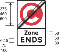 | |
| 7 | Diagram 1068 Road marking indicating the commencement of a congestion charging zone |  | |
| 8 | Diagram 1069 Road marking giving advance warning of a congestion charging zone |  |
PART 5The Schedule 8 General Directions
1. The signs provided for—
(a)in the sign table in Part 2; and
(b)at items 1, 2, 6 and 7 of the sign table in Part 4,
must only be placed to indicate the effect of an Act, order, regulation, bylaw, resolution or notice which restricts or prohibits the use of the road by traffic.
2. An upright sign mentioned in paragraph 1 must be placed as near as practicable to the point the restriction or prohibition begins or ends.
Regulation 3, Direction 3
SCHEDULE 9Regulatory signs at junctions and miscellaneous regulatory signs
PART 1Provisions applicable to signs in Part 2
1. The information or requirement of a description in column 2 of an item in the sign table in Part 2 must be conveyed by a sign that is —
(a)of the colour and type shown in the diagram in column 3; and
(b)complies with the requirements as to size given in column 4.
2. A provision of Part 8 applies to a sign provided for in Part 2 where indicated in column 5 of the Part 2 sign table (by reference to a paragraph number in Part 8).
3. A Schedule 9 General Direction applies to a sign provided for in Part 2 where indicated in column 6 of the Part 2 sign table (by reference to a number equivalent to the general direction in Part 9).
PART 2Signs at junctions
Sign table — Schedule 9, Part 2
(1) Item | (2) Description | (3) Diagram | (4) Permitted sizes | (5) Applicable provisions in Part 8 | (6) Schedule 9 General Directions |
|---|---|---|---|---|---|
| 1 | Diagram 601.1 Vehicular traffic must comply with the requirements specified in paragraph 1 or 2 of Part 7 |  | Sign height 750, 900, 1200 | 1, 2, 7 | 3, 4, 8 |
| 2 | Diagram 602 Vehicular traffic must comply with the requirements specified in paragraph 3 or 4 of Part 7 |  | Sign height 600, 750, 900, 1200, 1500 | 1, 7 | 5, 8 |
| 3 | Diagram 608 Dual carriageway road (associated plate for items 1 and 2) |  | x-height of legend: 50, 62.5, 75, 100, 125 | 10 | |
| 4 | Diagram 778 Open railway level crossing without light signals (associated plate for item 2) |  | Sign height 420, 525, 630 | 11 | |
| 5 | Diagram 778.1 Open tramway level crossing without light signals (associated plate for item 2) |  | Sign height 300, 375, 450 | 11 | |
| 6 | Diagram 611.1 Vehicles entering the junction must comply with the requirements prescribed in paragraph 5 of Part 7 |  | Sign height 600, 750, 900 | 1, 3, 7 | 6, 8 |
PART 3Provisions applicable to signs in Part 4
1. The information or requirement of a description in column 2 of an item in the sign table in Part 4 must be conveyed by a sign that is—
(a)of the colour and type; and
(b)complies with the requirements as to size,
provided for in the diagram in column 3 at that item, or that diagram as varied in accordance with column 4.
2. A provision of Part 8 applies to a sign provided for in Part 4 where indicated in column 5 of the sign table (by reference to a paragraph number in Part 8).
3. A Schedule 9 General Direction applies to a sign provided for in Part 4 where indicated in column 6 (by reference to a number equivalent to the general direction in Part 9).
PART 4Other regulatory signs
Sign table — Schedule 9, Part 4
(1) Item | (2) Description | (3) Diagram | (4) Permitted variants | (5) Applicable provisions in Part 8 | (6) Schedule 9 General Directions |
|---|---|---|---|---|---|
| 1 | Diagram 651 Use of verge maintained in mown or ornamental condition by specified traffic prohibited |  | 1. “animals”, or the right hand symbol and “pedestrians”, may be omitted, or that symbol and both words may be omitted 2. The arrow may be varied to point horizontally to the right, or may be omitted | 8 | 1, 13 |
| 2 | Diagram 626.2A Vehicles exceeding the maximum gross weight indicated prohibited from crossing the bridge or other structure with exemption for empty vehicles |  | 1. “18t” may be varied to “3t”, “7.5t”, “10t”, “13t”, “26t” or “33t” 2. “WEAK BRIDGE” may be varied to “WEAK ROAD” 3. The bottom panel may be omitted | 1, 7 | 2 |
| 3 | Diagram 622.10 Vehicles carrying dangerous goods within the tunnel restriction code indicated by the sign prohibited |  | The tunnel restriction code letter “B” may be varied to “C”, “D” or “E” as appropriate | 7 | 1 |
| 4 | Diagram 784.1 Drivers of large or slow vehicles must stop and telephone in accordance with the provisions of paragraph 6 of Part 7 before using a level crossing |  | The words “must phone” may be varied to “must use SOS phone” | 1, 2, 7 | |
| 5 | Diagram 652 One-way traffic |  | 7 | 1 | |
| 6 | Diagram 960.1 One-way road with a mandatory contraflow cycle lane |  | The number of upward pointing arrows may be varied to indicate the number of lanes available to all traffic | 1 | |
| 7 | Diagram 960.2 One-way road with contraflow pedal cycles |  | 1 | ||
| 8 | Diagram 960 One-way road with a contraflow bus and cycle lane |  | 1. The number of upward pointing arrows may be varied to indicate the number of lanes available to all traffic 2. The cycle symbol may be omitted and the downward pointing arrow centred below the bus symbol 3. The bus symbol may be varied to the local bus symbol shown in the diagram at item 10 | 1 | |
| 9 | Diagram 959.1 With-flow cycle lane with indication of times of operation |  | 1. In the upper panel— (a) the position of the vertical line and symbol may be varied to reflect the layout of the road marking at item 7 in the sign table in Part 6; and (b) an additional vertical line may be added 2. The time period may be varied 3. The bottom panel may be omitted | ||
| 10 | Diagram 959B Nearside with-flow bus lane, which authorised vehicles, taxis, solo motor cycles and pedal cycles may also use, with indication of times of operation |  | 1. In the upper panel— (a) “authorised vehicles” or “taxi” or both may be omitted; (b) the solo motor cycle symbol may be omitted; (c) the local bus symbol may be varied to the bus symbol shown at item 8; (d) the position of the vertical line and symbols may be varied to reflect the layout of the road marking at item 11 in the sign table in Part 6; and (e) an additional vertical line may be added 2. The time period may be varied 3. The bottom panel may be omitted | 1 | |
| 11 | Diagram 964 End of with-flow bus lane |  | 1 | ||
| 12 | Diagram 2602.3 The number of a route for pedal cycles forming part of a national or regional cycle route network |  | 1. The route number may be varied as appropriate and may include capital letters 2. The route number may be shown in brackets 3. Additional route numbers, in brackets, may be shown 4. The background colour may be varied to blue when placed on a regional cycle route 5. When indicating a route other than a national or regional cycle route network, the route number, background and border may be in any contrasting colours | 7 | |
| 13 | Diagram 2901 Regulations in force under section 17 of the 1984 Act start to apply to the road at this point |  | 1. The motorway number may be varied as appropriate and may be placed centrally above the motorway symbol 2. The motorway number may be shown in brackets 3. The motorway number may be expressed in the form “A 123 (M)” and “(M)” may be placed centrally below “A 123” | 7 | |
| 14 | Diagram 2930 Regulations referred to in this column in respect of item 13 cease to apply ahead |  | “1 mile” may be varied to “½ mile” | 7 | |
| 15 | Diagram 2931 Regulations referred to in this column in respect of item 13 cease to apply at this point |  | 7 | ||
| 16 | Diagram 2932 Entrance to a motorway service area, maintenance compound or similar facility contained within a length of a motorway and indicating that Regulations in force under section 17 of the 1984 Act cease to apply at this point |  |
PART 5Provisions applicable to road markings in Part 6
1. The information, requirement, restriction or prohibition of a description in column 2 of an item in the sign table in Part 6 must be conveyed by a road marking that is of the size, colour and type shown in the diagram in column 3.
2. A provision of Part 8 applies to a sign provided for in Part 6 where indicated in column 4 of the table (by reference to a paragraph number in Part 8).
3. A Schedule 9 General Direction applies to a sign provided for in Part 6 where indicated in column 5 (by reference to a number equivalent to the general direction in Part 9).
4. Where “longitudinal marking” is mentioned in respect of an item in the table, the expression indicates a marking to be laid on the carriageway of a road longitudinally to the flow of traffic.
PART 6Regulatory road markings
Sign table — Schedule 9, Part 6
(1) Item | (2) Description | (3) Diagram | (4) Applicable provisions in Part 8 | (5) Schedule 9 General Directions |
|---|---|---|---|---|
| 1 | Diagram 1002.1 Vehicular traffic must not proceed beyond the line when required to stop by the stop sign |  | 13 | 4 |
| 2 | Diagram 1022 Approach to a road junction or level crossing at or near which is placed the marking at item 1 of this table and the stop sign |  | 13 | 4 |
| 3 | Diagram 1003A Vehicular traffic must give way in accordance with the requirements in paragraph 7 of Part 7 |  | 1, 13 | 3 |
| 4 | Diagram 1023A Approach to a road junction, level crossing or road narrowing at or near which is placed the marking in item 3 or 6 of this table |  | 13 | 12 |
| 5 | Diagram 1003.4 Marking used in conjunction with the sign at item 6 of the sign table in Part 2 for conveying the requirements in paragraph 5 of Part 7 (Alternative sizes) |  | 4, 13 | 6 |
| 6 | Diagram 1003.3 Vehicular traffic approaching a roundabout with a small central island or approaching a junction indicated by the marking shown in item 5 of this sign table should give way at, or immediately beyond, the line to traffic circulating on the carriageway of the roundabout | 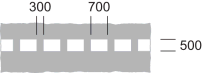 | 13 | |
| 7 | Diagram 1049B Boundary of a mandatory cycle lane or division of a route into that part reserved for pedal cycles and that part reserved for pedestrians conveying the requirements at paragraph 12 of Part 7 (Longitudinal marking) |  | 1, 9 | 1 |
| 8 | Diagram 1049.1 Division of a route into that part reserved for pedal cycles and that part reserved for pedestrians (Longitudinal marking) |  | 6 | 1 |
| 9 | Diagram 1003B Cyclists must give way in accordance with the requirements prescribed in paragraph 8 of Part 7 |  | 1 | |
| 10 | Diagram 1023B Approach to a road junction on a cycle lane or track, or a place where cyclists must give way to pedestrians, at or near which is also placed the marking at item 9 |  | 14 | |
| 11 | Diagram 1049A Boundary of a bus lane or other designated lane used by motor vehicles (Longitudinal marking) |  | 13 | 1 |
| 12 | Diagram 1050 Direction of possible traffic movements at the end of a nearside with-flow bus lane or other designated lane, or where there is an intermediate discontinuation of the lane on the approach to a junction (alternative types) |  | 1 | |
| 13 | Diagram 1050.1 Direction of possible traffic movements at the end of an off side with-flow bus lane or other designated lane, or where there is an intermediate discontinuation of the lane on the approach to a junction (alternative types) |  | 1 | |
| 14 | Diagram 1048 Traffic lane reserved for buses and other vehicles as indicated on the sign at item 8 or 10 in the sign table in Part 4 |  | 1 | |
| 15 | Diagram 1048.5 Road or part of a road with access permitted only for buses and other vehicles when so indicated by any of the signs at items 10, 33 to 35 and 37 to 40 in the sign table in Part 2 of Schedule 3 (Alternative types) |  | 1 | |
| 16 | Diagram 1048.2A Road or part of a road with access permitted only for tramcars | 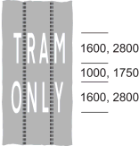 | 1 | |
| 17 | Diagram 1046 No entry for vehicular traffic (Alternative types) |  | 13 | 1 |
| 18 | Diagram 1046.1 Entry by vehicular traffic to a play street restricted (Alternative types) |  | 13 | 1 |
| 19 | Diagram 1036.1 Vehicular traffic must turn left (Alternative types) |  | 13 | 1 |
| 20 | Diagram 1036.2 Vehicular traffic must only proceed ahead (Alternative types) |  | 13 | 1 |
| 21 | Diagram 1037.1 Vehicular traffic must turn right (Alternative types) |  | 13 | 1 |
| 22 | Diagram 1042 Division of traffic lanes on a length of carriageway, or between the main carriageway and slip road, of a motorway or all-purpose dual carriageway road, or part of the carriageway between two lanes at a roundabout which vehicular traffic must not enter except in emergency (alternative types) |  | 1, 12, 13, 14 | |
| 23 | Diagram 1013.1 Alternative methods of indicating to vehicular traffic the requirements and the warning in paragraphs 9 and 10 of Part 7 |  | 1, 2, 10, 13 | |
| 24 | Diagram 1013.5 Division of traffic lanes on a length indicating to vehicular traffic the requirements in paragraph 9 of Part 7 and used in the circumstances for which the signs at items 17 to 20 in the Part 2 sign table in Schedule 11 are used |  | 1, 2, 11, 13 | |
| 25 | Diagram 1043 Marking conveying the requirements in paragraph 11 of Part 7 |  | 1, 5 | 9 |
| 26 | Diagram 1045 Area of carriageway, subject to two-way traffic, at a level crossing which vehicles must not enter in a manner which then causes any part of the vehicle to remain at rest within the marked area due to the presence of stationary vehicles |  | 1, 15 | |
| 27 | Diagram 1045.1 Area of carriageway, subject to one-way traffic, at a level crossing which vehicles must not enter in a manner which then causes any part of the vehicle to remain at rest within the marked area due to the presence of stationary vehicles |  | 1, 16 |
PART 7The significance of particular signs in Schedule 9
Stop sign
1. Subject to paragraph 2, the requirements conveyed to vehicular traffic on roads by a stop sign are that—
(a)every vehicle must stop before crossing the transverse line provided for at item 1 of the sign table in Part 6 of this Schedule, or if that line is not clearly visible, before entering the major road in respect of which the stop sign has been provided; and
(b)no vehicle must cross the transverse line, or if that line is not clearly visible, enter the major road in respect of which the stop sign has been provided, so as to be likely to endanger any person, or to cause the driver of another vehicle to change its speed or course in order to avoid an accident.
2. The requirements conveyed to vehicular traffic on roads by a stop sign when placed at a level crossing are that—
(a)every vehicle must stop before crossing the transverse line, or if that line is not clearly visible, before entering the level crossing; and
(b)no vehicle must cross the transverse line, or if that line is not clearly visible, enter the level crossing so as to be likely to endanger the driver of, or any passenger in, any railway vehicle or tramcar or to cause that driver to change speed in order to avoid an accident.
Give way sign
3. Subject to paragraph 4, the requirements conveyed to vehicular traffic on roads by a give way sign are that no vehicle is to cross the transverse line provided for at item 3 of the sign table in Part 6 of this Schedule nearer to the major road at the side of which that line is placed, or if that line is not clearly visible, enter that major road, so as to be likely to endanger any person, or to cause the driver of another vehicle to change its speed or course in order to avoid an accident.
4. The requirements conveyed to vehicular traffic on roads by a give way sign when placed in combination with the sign at item 4 or 5 of the sign table in Part 2 of this Schedule are that no vehicle must cross the transverse line nearer to the level crossing at the side of which that line is placed, or if that line is not clearly visible, enter that level crossing, so as to be likely to endanger the driver of, or any passenger in, any railway vehicle or tramcar or to cause that driver to change the speed of his or her vehicle in order to avoid an accident.
Priority to right sign
5.—(1) The requirements conveyed to vehicular traffic on roads by a sign provided for at item 6 of the sign table in Part 2 of this Schedule are that—
(a)a vehicle entering the junction must give priority to vehicles coming from the right—
(i)at the transverse road marking provided for at item 6 of the sign table in Part 6 of this Schedule;
(ii)at the transverse road marking provided for at item 3 of the sign table in Part 6 of this Schedule; or
(iii)if a marking is not for the time being visible, at the junction;
(b)a vehicle proceeding through the junction must keep to the left of the white circle at the centre of the marking provided for at item 5 of the sign table in Part 6 of this Schedule (“the diagram 1003.4 marking”), unless the size of the vehicle or the layout of the junction makes it impracticable to do so; and
(c)no vehicle is to proceed past the diagram 1003.4 marking in a manner, or at a time, likely to endanger any person, or to cause the driver of another vehicle to change its speed or course in order to avoid an accident.
Permission to cross sign
6.—(1) Subject to sub-paragraph (2) the requirements conveyed to vehicular traffic on roads by a sign provided for at item 4 of the sign table in Part 4 of this Schedule are that no abnormal transport unit is to proceed onto or over a level crossing unless—
(a)the driver of the unit has used a telephone provided at or near the crossing for the purpose of obtaining from a person, authorised in that behalf by the railway or tramway authority, permission for the unit to proceed;
(b)that permission has been obtained before the unit proceeds; and
(c)the unit proceeds in accordance with any terms attached to that permission.
(2) Sub-paragraph (1)(b) and (c) does not apply if—
(a)the driver uses the telephone at the crossing and receives an indication for not less than two minutes that the telephone at the other end of the telephone line is being called, but no duly authorised person answers it, or the driver receives no indication at all due to a fault or malfunction of the telephone; and
(b)the driver then drives the unit on to the crossing with the reasonable expectation of crossing it within times specified in a railway or tramway notice at the telephone as being times between which railway vehicles or tramcars do not normally travel over that crossing.
Give way marking
7. The requirements conveyed to vehicular traffic on roads by a road marking provided for at item 3 of the sign table in Part 6 of this Schedule are—
(a)except as provided in paragraphs (b) to (d), that no vehicle may proceed past the transverse line which is the nearer to the major road into that road in a manner or at a time likely to endanger the driver of, or any passenger in, a vehicle on the major road or to cause the driver of such a vehicle to change its speed or course in order to avoid an accident;
(b)where the transverse lines are placed at a level crossing, that no vehicle may proceed past such one of those lines as is the nearer the level crossing in a manner or at a time likely to endanger the driver of, or any passenger in, a railway vehicle or tramcar, or to cause that driver to change the speed of his or her vehicle in order to avoid an accident;
(c)where the transverse lines are placed in advance of a point in the road where the width of the carriageway narrows significantly, that no vehicle may proceed past such one of those lines as is nearer to the point of narrowing in a manner or at a time likely to endanger the driver of, or any passenger in, a vehicle that is proceeding in the opposite direction to the first-mentioned vehicle, or cause the driver of such a vehicle to change its speed or course in order to avoid an accident;
(d)where the transverse lines are placed in advance of a length of the carriageway of the road where a cycle track crosses the road along a route parallel to the transverse lines, that no vehicle may proceed past such one of those lines as is the nearer the cycle track, in a manner or at a time likely to endanger any cyclist proceeding along the cycle track or to cause such a cyclist to change speed or course in order to avoid an accident.
Cyclists to give way
8. A cycle must not be ridden across the transverse line provided for at item 9 of the sign table in Part 6 of this Schedule in a manner or at a time that is likely to endanger any person, or to cause the driver of another vehicle to change its speed or course in order to avoid an accident.
No stopping or crossing white line marking
9.—(1) The requirements conveyed to vehicular traffic on roads by a road marking provided for at items 23 and 24 of the sign table in Part 6 of this Schedule are that—
(a)subject to sub-paragraphs (2) to (4), no vehicle is to stop on any length of road along which the marking has been placed at any point between the ends of the marking; and
(b)subject to sub-paragraph (5), every vehicle proceeding on any length of road along which the marking has been so placed, as viewed in the direction of travel of the vehicle, a continuous line is on the left of a broken line or of another continuous line, must be so driven as to keep the first-mentioned continuous line on the right hand or off side of the vehicle.
(2) Nothing in sub-paragraph (1)(a) applies so as to prevent a vehicle stopping on any length of road so long as may be necessary for any of the purposes specified in sub-paragraph (3) if the vehicle cannot be used for such a purpose without stopping on the length of road.
(3) The purposes are—
(a)to enable a person to board or alight from the vehicle,
(b)to enable goods to be loaded on to or to be unloaded from the vehicle,
(c)to enable the vehicle to be used in connection with—
(i)any operation involving building, demolition or excavation;
(ii)the removal of any obstruction to traffic;
(iii)the maintenance, improvement or reconstruction of the length of road; or
(iv)the laying, erection, alteration, repair or cleaning in or near the length of road of any sewer or of any main, pipe or apparatus for the supply of gas, water or electricity, or of any electronic communications apparatus kept installed for the purposes of an electronic communications code system or of any other electronic communications apparatus lawfully kept installed in any position.
(4) Nothing in sub-paragraph (1)(a) applies—
(a)so as to prevent a vehicle stopping in a lay-by;
(b)to a vehicle being used for at least one of the following purposes—
(i)fire and rescue authority;
(ii)Scottish Fire and Rescue Service;
(iii)traffic officer;
(iv)ambulance;
(v)providing a response to an emergency at the request of an NHS ambulance service;
(vi)bomb or explosive disposal;
(vii)special forces;
(viii)police; and
(ix)National Crime Agency.
(c)to a pedal cycle;
(d)to a vehicle stopping in any case where the person in control of the vehicle is required by law to stop, or is obliged to do so in order to avoid an accident, or is prevented from proceeding by circumstances outside the person’s control;
(e)to anything done with the permission or at the direction of a constable in uniform, traffic officer in uniform or in accordance with the direction of a traffic warden; or
(f)to a vehicle on a road with more than one traffic lane in each direction.
(5) Nothing in sub-paragraph (1)(b) is to be taken to prohibit a vehicle from being driven across, or so as to straddle, the continuous line referred to in that paragraph, if it is safe to do so and if necessary to do so—
(a)to enable the vehicle to enter, from the side of the road on which it is proceeding, land or premises adjacent to the length of road on which the line is placed, or another road joining that road;
(b)in order to pass a stationary vehicle;
(c)owing to circumstances outside the control of the driver;
(d)in order to avoid an accident;
(e)in order to pass a road maintenance vehicle which is in use, is moving at a speed not exceeding 10 mph, and is displaying to the rear a sign provided for at item 9 or 10 of the sign table in Part 6 of Schedule 13;
(f)in order to pass a pedal cycle moving at a speed not exceeding 10 mph;
(g)in order to pass a horse that is being ridden or led at a speed not exceeding 10 mph; or
(h)for the purposes of complying with any direction of a constable in uniform, a traffic officer in uniform or a traffic warden.
10. The warning conveyed to vehicular traffic on roads by the road marking provided for at item 23 of the sign table in Part 6 of this Schedule is that no vehicle while travelling next to a broken line placed on the left of a continuous line, as viewed in the direction of travel of the vehicle, should cross or straddle the first-mentioned line unless it is seen by the driver of the vehicle to be safe to do so.
Box junctions
11.—(1) Subject to sub-paragraphs (2), (3) and (4), the yellow criss-cross marking provided for at item 25 of the sign table in Part 6 conveys the prohibition that a person must not cause a vehicle to enter the box junction so that the vehicle has to stop within the box junction due to the presence of stationary vehicles.
(2) Subject to sub-paragraph (4) the marking when placed as a box junction within sub-paragraph (6)(c) of the definition of that expression conveys the prohibition that a person must not cause a vehicle to enter the box junction so that the vehicle has to stop within the box junction due to the presence of oncoming vehicles or other stationary vehicles beyond the box junction.
(3) The prohibition in sub-paragraph (1) does not, in respect of a box junction within sub-paragraph (6)(a) of the definition of that expression, apply to a person who—
(a)causes a vehicle to enter the box junction for the purpose of turning right; and
(b)stops the vehicle within the box junction for so long as the vehicle is prevented from completing the right turn by an oncoming vehicle or other vehicle which is stationary whilst waiting to complete a right turn.
(4) When a vehicle is being used for at least one of the purposes mentioned at sub-paragraph (5) and the observance of the prohibition in sub-paragraph (1) or (2) would be likely to hinder the use of that vehicle for that purpose, then that prohibition does not apply to the driver of the vehicle.
(5) The purposes are—
(a)fire and rescue authority;
(b)Scottish Fire and Rescue Service;
(c)ambulance;
(d)providing a response to an emergency at the request of an NHS ambulance service;
(e)bomb or explosive disposal;
(f)special forces;
(g)police; and
(h)National Crime Agency.
(6) For the purposes of this paragraph “box junction” means an area of the carriageway where the marking has been placed and which is—
(a)at a junction between two or more roads;
(b)at a gyratory system or roundabout;
(c)along a length of a two-way road (other than at a junction), the carriageway of which is not greater than 4.5 metres wide at its narrowest point; or
(d)on the length of road adjacent to the vehicular entrance to the premises of a fire, police or ambulance station; and
(7) A reference in this paragraph (however expressed) to a vehicle which is stationary or stops within a box junction includes a vehicle which is stationary whilst part of it is within the box junction.
Mandatory with flow cycle lanes
12.—(1) This paragraph applies to the road marking provided for at item 7 of the sign table in Part 6—
(a)when that marking is being used to separate a cycle lane from another part of the carriageway; and
(b)where the direction of travel along the cycle lane and the part of the carriageway from which it is separated is the same.
(2) Subject to sub-paragraphs (3) to (5), the marking conveys the requirement that a vehicle, other than a pedal cycle, must not be driven, or ridden, in the cycle lane during the cycle lane’s hours of operation (which may be all the time).
(3) Sub-paragraph (2) does not prohibit a vehicle from crossing into the part of the carriageway reserved for pedal cycles, or straddling the marking, if it is safe and necessary to do so—
(a)in order to pass a stationary vehicle;
(b)to enable the vehicle to enter, from the side of the road on which it is proceeding, land or premises adjacent to the length of road on which the line is placed, or another road joining that road;
(c)due to circumstances outside the control of the driver;
(d)in order to avoid an accident; or
(e)for the purpose of complying with any direction of a constable in uniform or a traffic warden.
(4) When a vehicle is being used for at least one of the purposes mentioned at sub-paragraph (5) and the observance of the prohibition in sub-paragraph (2) would be likely to hinder the use of the vehicle for that purpose, then that prohibition does not apply to the driver of the vehicle.
(5) The purposes are—
(a)fire and rescue authority;
(b)Scottish Fire and Rescue Service;
(c)ambulance;
(d)providing a response to an emergency at the request of an NHS ambulance service;
(e)bomb or explosive disposal;
(f)special forces;
(g)police; and
(h)National Crime Agency.
PART 8Provisions applicable to signs in Parts 2, 4 and 6
1.—(1) Subject to sub-paragraph (2), section 36 of the 1988 Act applies to the sign.
(2) Sub-paragraph (1) applies to the sign provided for at item 7 of the Part 6 sign table only where that marking is used to indicate the boundary of a mandatory with‑flow cycle lane during the cycle lane’s hours of operation (which may be all the time).
2. The sign is specified for the purposes of column 5 of the entry in Schedule 2 to the Road Traffic Offenders Act 1988(58) relating to offences under section 36 of the 1988 Act.
3. Where the sign is placed temporarily on a road by a constable or person acting under the instructions (whether general or specific) to the chief officer of police for the purposes of indicating a temporary statutory provision, the diameter may be reduced to not less than 200 mm.
4. The central part of the road marking must not project above the surface of the adjacent carriageway more than 125 mm at its highest point or 6 mm at its perimeter.
5.—(1) The overall shape and size of the road marking, within the overall dimensions shown, may be varied as appropriate.
(2) Parts of a boundary line may be omitted when the edge of the marking is adjacent to a raised kerb.
(3) Parts of the marking may be omitted where tram rails cross the marking.
(4) Parts of the marking may be omitted to indicate the edge of the path taken by a tramcar and, where parts of the marking are so omitted, the remaining parts must be bounded by a continuous yellow line.
6. The height of the marking above the surface of the adjacent carriageway must be within the range of dimensions indicated on the lower part of the diagram at item 8 of Part 6 in illustrating the cross-section of the marking.
7.—(1) Subject to sub paragraph (2), where the sign is placed on a road subject to a speed limit greater than 20 mph and is within 50 metres of any lamp which forms part of a system of street-lighting, the illumination requirements are—
(a)where that system of street-lighting is illuminated throughout the hours of darkness, the sign must be illuminated by internal or external lighting for so long as that system is illuminated and may also be reflectorised; or
(b)where that system of street-lighting is not illuminated throughout the hours of darkness–
(i)the sign must be illuminated by internal or external lighting for so long as that system is illuminated and must also be reflectorised; or
(ii)the sign must be illuminated throughout the hours of darkness by internal or external lighting and may also be reflectorised.
(2) Sub paragraph (1) applies to the sign at item 5 of the Part 4 table only when placed within 50 metres of any junction with another road from which traffic can approach it.
8. The sign need not be illuminated.
9. The road marking must be reflectorised where indicating the boundary of a mandatory cycle lane.
10.—(1) When the road marking is used, studs must also be placed.
(2) The studs must incorporate—
(a)white reflectors;
(b)white retroreflecting material;
(c)a light source that emits, during the hours of darkness, a steady white light; or
(d)any combination.
(3) In the case of the markings shown in parts A and C of the diagram, the studs must be fitted as a single line between the continuous line and the non-continuous line of the marking and be spaced not less than 3 metres nor more than 4.5 metres apart.
(4) In the case of the marking shown in in part B of the diagram, the studs must be fitted either in opposite pairs within the width of each of the two lines that run longitudinally to the flow of traffic or as a single line between those lines and in either case the studs must be placed not less than 3 metres nor more than 4.5 metres from the nest stud in the line.
(5) In the case of the marking shown in part D of the diagram, the studs must form a single line between the continuous line and the non-continuous line of the marking and be spaced not less than 3 metres nor more than 4.5 metres apart and the direction of the line of studs is not to be changed by reason of the switching of the continuous and non-continuous lines of the marking as shown in the diagram at that part.
(6) The external part of the stud that is visible when the stud is in place must be—
(a)white;
(b)of a natural metallic finish;
(c)of another neutral colour; or
(d)clear,
or any combination (but see sub-paragraph (7) for an exception).
(7) The external part of a stud that is visible when the stud is in place temporarily during road works must be fluorescent green-yellow except to the extent—
(a)it consists of white reflectors or retroreflecting material; or
(b)it is necessary for it to be a different colour or clear in order for the stud to emit white light.
11.—(1) When the marking is used, studs must also be placed.
(2) The studs must incorporate—
(a)white reflectors;
(b)white retroreflecting material; or
(c)a light source that emits, during the hours of darkness, a steady white light,
or any combination.
(3) The studs must be fitted in opposite pairs within the width of each of the two lines that run longitudinally to the flow of traffic and the studs must be placed not less than 3 metres nor more than 4.5 metres apart.
(4) The external part of the stud that is visible when the stud is in place must be—
(a)white;
(b)of a natural metallic finish;
(c)of another neutral colour; or
(d)clear,
or any combination (but see sub-paragraph (5) for an exception).
(5) The external part of a stud that is visible when the stud is in place temporarily during road works must be fluorescent green-yellow except to the extent—
(a)it consists of white reflectors or retroreflecting material; or
(b)it is necessary for it to be a different colour or clear in order for the stud to emit white light.
12.—(1) When the marking is used, studs may also be placed.
(2) The studs must incorporate—
(a)red reflectors;
(b)red retroreflecting material; or
(c)a light source that emits, during the hours of darkness, a steady red light,
or any combination.
(3) The studs must be fitted at the side of, and adjacent to the solid line forming the boundary of the marking.
(4) The external part of the stud that is visible when the stud is in place must be—
(a)red
(b)white;
(c)of a natural metallic finish;
(d)of another neutral colour; or
(e)clear,
or any combination (but see sub-paragraph (5) for an exception).
(5) The external part of a stud that is visible when the stud is in place temporarily during road works must be fluorescent green-yellow except to the extent—
(a)it consists of red reflectors or retroreflecting material; or
(b)it is necessary for it to be a different colour or clear in order for the stud to emit red light.
13. The road marking must be reflectorised.
14. The road marking may, except at a roundabout, be varied by replacing the boundary line with the marking at item 12 or 13 of the sign table in Part 4 of Schedule 11.
15. The road marking may be varied as follows—
(a)the pattern of diagonal lines on each side of the level crossing may be extended longitudinally within the limit of the marking by increasing the number of diamond shapes on the approach side and the number of diagonal crosses on the leaving side; and
(b)parts of the marking may be omitted to accommodate the road markings at—
(i)diagram A of item 23 in the Part 6 sign table; or
(ii)item 2 or 3 of the sign table in Part 4 of Schedule 11.
16. The road marking may be varied as follows—
(a)the pattern of diagonal lines on each side of the level crossing may be extended longitudinally within the limit of the marking by increasing the number of diamond shapes on the approach side and the number of diagonal crosses on the leaving side; and
(b)parts of the marking may be omitted to accommodate the road markings at item 2 or 3 of the sign table in Part 4 of Schedule 11.
PART 9The Schedule 9 General Directions
1.—(1) Subject to sub-paragraph (2), the sign must only be placed to indicate the effect of an Act, order, regulation, bylaw, resolution or notice which prohibits or restricts the use of the road by traffic.
(2) Sub-paragraph (1) does not apply to the sign provided for at item 7 of the Part 6 sign table where the sign is used to indicate the boundary of a mandatory with-flow cycle lane.
2. The sign must only be placed to indicate the effect of a statutory provision which restricts the use of the road carried by a bridge or other structure—
(a)in the case of vehicles required to be marked with their maximum gross weight, to any vehicle with a maximum gross weight not exceeding that indicated on the sign; or
(b)in the case of vehicles not required to be marked with their maximum gross weight but required to be marked with their unladen weight, to any vehicle with an unladen weight not exceeding the gross weight indicated on the sign.
3. The sign may only be placed at a junction with another road if the same sign has not been placed on the other road so as to control traffic passing through the junction on that other road.
4.—(1) The stop sign must only be placed in conjunction with the road markings at items 1 (“the diagram 1002.1 marking”) and 2 (“the diagram 1022 marking”) of the sign table in Part 6.
(2) The diagram 1002.1 marking must only be placed in conjunction with the stop sign and the diagram 1022 marking.
(3) The diagram 1022 marking must only be placed in conjunction with the stop sign and the diagram 1002.1 marking.
5. The sign provided for at item 2 of the sign table in Part 2 must only be placed in conjunction with the road markings at items 3 and 4 of the sign table in Part 6.
6.—(1) The sign provided for at item 6 in the sign table in Part 2 must only be placed in conjunction with—
(a)the road markings provided for at item 5 and 6 of the sign table in Part 6; or
(b)the road markings shown in that sign table at items 3, 4 and 5 where the sign is placed in conjunction with the sign at item 2 in the sign table in Part 2.
(2) The road marking provided for at item 5 of the sign table in Part 6 must only be placed in conjunction with the sign at item 6 of the sign table in Part 2.
7. The sign must only be placed in conjunction with a sign at item 28, 29, 30, 31 and 32 of the sign table in Part 2 of Schedule 2.
8.—(1) The requirement in paragraph 4, 5 or 6 to place a relevant upright sign in conjunction with a relevant marking does not apply during the execution of works if—
(a)those works necessitate the temporary removal of the marking; or
(b)the sign is placed only temporarily in connection with the execution of works on a road.
(2) For the purposes of sub-paragraph (1) “relevant upright sign” and “relevant marking” mean—
(a)in the case of paragraph 4, the sign and marking referred to in that paragraph;
(b)in the case of paragraph 5, the sign and marking referred to in that paragraph; and
(c)in the case of paragraph 6, the sign and marking referred to in that paragraph.
9. The road marking must not be placed on an area of carriageway at a gyratory system or roundabout unless entry of traffic into that area of carriageway is at all times controlled by traffic light signals.
10. The sign must only be placed in combination with the sign at item 1 or 2 of the sign table in Part 2.
11. The sign must only be placed in combination with the sign at item 2 of the sign table in Part 2.
12. The road marking must only be placed in conjunction with the road marking at item 3 or 6 of the sign table in Part 6.
13. The back of the sign may be of any colour.
14. The road marking may only be placed in conjunction with the road marking at item 9 of the sign table in Part 6.
Regulation 3, Direction 3
SCHEDULE 10Signs for speed limits
PART 1Provisions applying to signs in Part 2
1. Information or a restriction of a description in column 2 of an item in the Part 2 sign table must be conveyed by a sign which—
(a)is of the colour and type; and
(b)complies with the requirements as to size,
shown in the diagram in column 3 of the item, or that diagram as varied in accordance with column 4.
2. A provision of Part 3 applies to a sign provided for in the Part 2 sign table where indicated in column 5 of that table (by reference to a paragraph number in Part 3).
3. A Schedule 10 General Direction applies to a sign where indicated in column 6 of the Part 2 sign table (by reference to a number equivalent to the Schedule 10 General Direction in Part 4).
PART 2Signs and road markings indicating speed limits
Sign table — Schedule 10, Part 2
(1) Item | (2) Description | (3) Diagram | (4) Permitted variants | (5) Applicable provision in Part 3 | (6) Schedule 10 General Directions |
|---|---|---|---|---|---|
| 1 | Diagram 670 Maximum speed limit in mph |  | 1. The numerals may be varied 2. The diameter of the sign may be varied to 1300 mm when displayed as a variable message sign by means of light emitting characters and symbols | 1, 2, 3 | 2, 4, 6 |
| 2 | Diagram 671 National speed limits apply |  | 2, 3 | 3, 4 | |
| 3 | Diagram 672 Minimum speed limit in mph |  | The numerals may be varied | 2, 3 | 4 |
| 4 | Diagram 673 End of minimum speed limit |  | The numerals may be varied | 2, 3 | 4 |
| 5 | Diagram 674 Entrance to a zone where a maximum speed limit of 20 mph is in force |  | 1. The place name may be varied, omitted or varied to a road safety slogan 2. The symbol or pictogram in the lower panel may be varied or omitted 3. The place name may be in any style of lettering. Any contrasting colours except red may be used for the place name and the background of that part of the sign. Advertising material or political slogans must not be included on the sign 4 The lower panel may be omitted | 3 | 1, 4 |
| 6 | Diagram 675A End of a 20 mph speed limit zone with indication of maximum speed limit in mph | 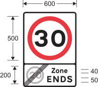 | The numerals in the upper panel may be varied | 3 | 4 |
| 7 | Diagram 675B End of a 20 mph speed limit zone with indication that national speed limits apply |  | 3 | 4 | |
| 8 | Diagram 676 Entrance to a zone where a maximum speed limit of 40 mph is in force | 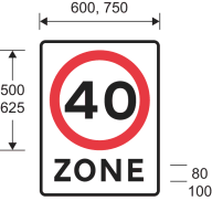 | 2, 3 | 4 | |
| 9 | Diagram 1065 Road marking indicating the maximum speed limit (Alternative sizes) |  | The numerals may be varied | 4 | 2, 4(a), 5 |
PART 3Provisions applying to signs in Part 2
1. Where the sign is a variable message sign which displays the numeral by means of light-emitting characters or symbols in such a way that the sign is only visible when associated equipment detects the presence of a vehicle exceeding the speed limit indicated by the sign, the variable message sign may display, beneath the sign displayed on it, the legend “SLOW DOWN” in characters having a height not less than one quarter of the height of the displayed sign.
2. Where the sign is a terminal sign and is erected on a trunk or principal road within 50 metres of any lamp lit by electricity that has been placed there in order to provide illumination to users of the road, the illumination requirements for the sign are—
(a)where the lamp is illuminated throughout the hours of darkness, the sign must be illuminated by internal or external lighting for so long as the lamp is illuminated and may also be reflectorised; or
(b)where the lamp is not illuminated throughout the hours of darkness–—
(i)the sign must be illuminated by internal or external lighting for so long as the lamp is illuminated and must also be reflectorised; or
(ii)the sign must be illuminated throughout the hours of darkness by internal or external lighting and may also be reflectorised.
3. Two or more signs placed at, or near, the same point for the same purpose must, if they are terminal signs, be illuminated by the same method.
4. The road marking must be reflectorised.
PART 4The Schedule 10 General Directions
1.—(1) The sign provided for at item 5 of the sign table in Part 2 (“the diagram 674 sign”) may only be placed where no part of the road to which the speed limit applies is more than 50 metres from a traffic calming feature.
(2) The restriction in sub-paragraph (1) does not apply in respect of a road which is a cul-de-sac that is less than 80 metres long.
(3) Each of the following is a traffic calming feature—
(a)a road hump constructed pursuant to section 90A of the Highways Act 1980(59) (“the 1980 Act”) or section 36 of the Roads (Scotland) Act 1984(60) and in accordance with the Highways (Road Humps) Regulations 1999(61) or the Road Humps (Scotland) Regulations 1998(62);
(b)traffic calming works constructed in accordance with section 90G of the 1980 Act(63) or section 39A of the Roads (Scotland) Act 1984(64) and in accordance with the Highways (Traffic Calming) Regulations 1999(65) or the Roads (Traffic Calming) (Scotland) Regulations 1994(66);
(c)a refuge for pedestrians which was constructed pursuant to section 68 of the 1980 Act, or section 27(c) of the Roads (Scotland) Act 1984, after 15th June 1999 and is constructed so as to encourage a reduction in the speed of traffic using the carriageway;
(d)a variation of the relative widths of the carriageway or of any footway pursuant to section 75 of the 1980 Act, or section 1(1) or 2(1) of the Roads (Scotland) Act 1984, which—
(i)was carried out after 15th June 1999 for the purpose of encouraging a reduction in the speed of traffic using the carriageway; and
(ii)had the effect of reducing the width of the carriageway;
(e)a horizontal bend in the carriageway through which all vehicular traffic has to change direction by no less than 70 degrees within a distance of 32 metres as measured at the inner kerb radius;
(f)a sign provided for at item 1 of the Part 2 sign table varied to “20”; or
(g)a road marking provided for at item 9 of that table varied to “20”.
(4) At least one traffic calming feature as defined in paragraph (2)(a) to (e) must be placed within the zone indicated by the diagram 674 sign.
(5) For the purposes of sub-paragraph (1), the distance of 50 metres is to be measured along roads to which the speed limit indicated by the diagram 674 sign applies.
2. The sign must not be placed as a repeater sign where the road is subject to a maximum speed limit of 30 mph and has a system of carriageway lighting.
3. The sign must not be placed as a repeater sign—
(a)on a motorway; or
(b)where a road, other than a motorway, does not have a system of carriageway lighting.
4. The sign—
(a)must only be placed to indicate the effect of an Act, order, regulation, bylaw, resolution or notice which restricts the use of the road by traffic; and
(b)when placed as a terminal sign, must be placed as near as practicable to the point that the speed limit begins or ends.
5. If the road marking is placed to indicate where a maximum speed limit commences, it must be placed in conjunction with an upright sign provided for at item 1, 5, 6 or 8 of the Part 2 sign table.
6.—(1) Sub-paragraph (2) applies where the backing board for the sign is yellow.
(2) When placed on the same backing board as the sign provided for at item 81 of the sign table in Part 2 of Schedule 11, the backing board may be of any shape.
Regulation 3, Direction 3
SCHEDULE 11Signs that give information, are advisory or guide traffic
PART 1Provisions applying to signs in Part 2
1. Except for item 75, a warning or information of a description in column 2 of an item in the Part 2 sign table must be conveyed by a sign which is—
(a)of the colour and type; and
(b)complies with the requirements as to size,
shown in the diagram in column 3 of the item, or that diagram as varied in accordance with column 4 (by reference to paragraphs in Part 5).
2. In respect of item 75 (traffic mirror), the mirror must be as specified in column 3.
3. A paragraph of Part 6, specified by reference to a number in column 5 of an item in the Part 2 sign table, applies to the sign provided for at that item.
4. A number in column 6 of an item in the Part 2 sign table indicates that the Schedule 11 General Direction bearing that number applies to the sign provided for at that item.
PART 2Advisory signs
Sign table — Schedule 11, Part 2
(1) Item | (2) Description | (3) Diagram | (4) Variants by reference to Part 5 | (5) Applicable provisions in Part 6 | (6) Schedule 11 General Directions |
|---|---|---|---|---|---|
| 1 | Diagram 811A and 811B Beginning and end of section of road where traffic has priority over vehicles from the opposite direction |  | 1, 2 | ||
| 2 | Diagram 810 One-way traffic (Sign for pedestrians) (Alternative types) |  | 5 | ||
| 3 | Diagrams 814.2 and 814.4 Ramped access to or from a pedestrian subway or overbridge |  | 1, 2, 4, 5, 54 | 5 | |
| 4 | Diagrams 814.1 and 814.3 Stepped access to and from a pedestrian subway or overbridge |  | 4 | 5 | |
| 5 | Diagram 816 No through road for vehicular traffic (Alternative types) |  | |||
| 6 | Diagram 816.1 Alternative to the sign shown at item 5 with a street nameplate |  | 7 | 5 | |
| 7 | Diagram 817 No through road for vehicular traffic in direction indicated from junction ahead (Alternative types) | 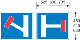 | 6 | ||
| 8 | Diagram 821 Road ahead only wide enough for one line of vehicles, and providing information about passing places (Alternative types) |  | 1 | ||
| 9 | Diagram 822 Passing place on narrow road |  | |||
| 10 | Diagrams 892 and 893 Name and length of a tunnel on a motorway (892) or all‑purpose road (893) |  | 8 | ||
| 11 | Diagram 818.1 Section of dual carriageway road ahead |  | 1, 2 | ||
| 12 | Diagram 818.1A Distance over which a short length of dual carriageway road beginning directly ahead extends (Alternative types) | 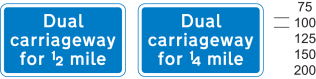 | |||
| 13 | Diagram 820.1 Absence of hard shoulder for the distance shown (Alternative types) | 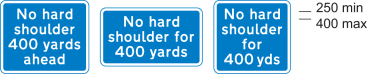 | 1 | ||
| 14 | Diagrams 873 and 874 Additional traffic joining from the left or right ahead (diagram shows blue background – for use on motorways) |  | 1, 2, 6, 26, 27 | ||
| 15 | Diagram 872.1 The number of traffic lanes reduces ahead (diagram shows blue background – for use on motorways) (Alternative types) | 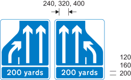 | 1, 2, 6, 26, 27 | ||
| 16 | Diagram 887 Overtaking lane ahead |  | 1, 2 | ||
| 17 | Diagram 888 Indication of length of road over which an overtaking lane is available on a single carriageway road, with a single traffic lane in the opposite direction (diagram shows green background – for use on primary routes) | 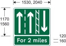 | 1, 27 | ||
| 18 | Diagram 889 Indication that only one lane of traffic, with no overtaking, is available on a single carriageway road with two traffic lanes in the opposite direction (diagram shows green background – for use on primary routes) | 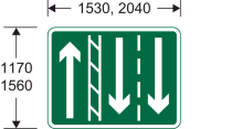 | 27 | ||
| 19 | Diagram 890 Distance ahead to a point where an overtaking lane ends on a single carriageway road (diagram shows green background – for use on primary routes) |  | 1, 2, 27 | ||
| 20 | Diagram 891 Distance ahead to a point where an overtaking lane ends on a single carriageway road on the approach to a dual carriageway road with only one traffic lane in each direction (diagram shows green background – for use on primary routes) |  | 1, 2, 27 | ||
| 21 | Diagrams 823, 824 and 825 Distance in hundreds of yards to a roundabout or the next point at which traffic may leave a route (diagram shows blue background – for use on motorways) |  | 4, 26, 27 | ||
| 22 | Diagram 877 Appropriate traffic lanes for different manoeuvres at a junction ahead (diagram shows white background – for use on non-primary routes) (Alternative types) | 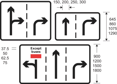 | 9, 26, 28 | ||
| 23 | Diagram 820 Route unsuitable for type of vehicle indicated (Alternative types) |  | 5(1) | ||
| 24 | Diagram 820A Road unsuitable for heavy goods vehicles (Alternative types) |  | 4, 5(1) | ||
| 25 | Diagram 829.5 Area where police carry out checks on the speed of vehicles | 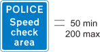 | |||
| 26 | Diagram 829.6 Waiting place for police or authorised vehicles only (Alternative types) |  | |||
| 27 | Diagram 881 Start of a home zone designated under section 268 of the Transport Act 2000(67), or section 74(1) of the Transport (Scotland) Act 2001(68) |  | 24 | ||
| 28 | Diagram 882 End of a home zone indicated by the sign at item 27 |  | |||
| 29 | Diagram 886 Road ahead where motorists, cyclists and pedestrians should expect to share the same space |  | |||
| 30 | Diagram 884 Start of a quiet lane in England designated under section 268 of the Transport Act 2000 | 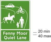 | 24 | ||
| 31 | Diagram 885 End of designated quiet lane in England |  | |||
| 32 | Diagram 883 Indication of the start of area with traffic calming features (within the meaning of paragraph 1(3) of the Schedule 10 General Directions) |  | 1, 5(1), 24 | ||
| 33 | Diagram 953.3 Entrance to a bus station, depot or garage |  | 5 | ||
| 34 | Diagram 962 Bus lane or lanes on a road at junction ahead, with indication of times of operation (Alternative types) | 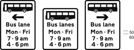 | 10 | ||
| 35 | Diagram 962.1 Cycle lane on a road at junction ahead or cycle track crossing road, with indication of times of operation |  | 4, 10, 12 | ||
| 36 | Diagram 962.2 Contraflow bus lane ahead on a road at a junction which pedal cycles may also use (Alternative types) |  | |||
| 37 | Diagram 958 With-flow bus lane ahead which authorised vehicles, solo motor cycles, pedal cycles and taxis may also use, with indication of times of operation |  | 10, 11, 13, 14 | ||
| 38 | Diagram 958.1 With-flow mandatory cycle lane ahead, with indication of times of operation |  | 10, 14 | ||
| 39 | Diagram 2602.2 Numbered route for pedal cycles forming part of a regional (blue number patch) or national (red number patch) cycle route network (Alternative types) | 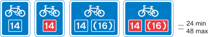 | 25 | 5 | |
| 40 | Diagram 963 Direction in which pedestrians should look for approaching traffic when crossing a bus lane (Alternative types) |  | 5 | ||
| 41 | Diagram 963.1 Direction in which pedestrians should look for approaching pedal cycles when crossing a cycle lane (Alternative types) |  | 15 | 5 | |
| 42 | Diagram 963.2 Direction in which pedestrians should look for approaching traffic when crossing a contraflow bus lane which pedal cycles may also use (Alternative types) | 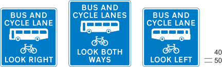 | 5 | ||
| 43 | Diagram 963.3 Direction in which pedestrians should look for approaching tramcars when crossing a tramway (Alternative types) | 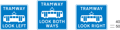 | 5 | ||
| 44 | Diagram 967 Route recommended for pedal cycles on the main carriageway of a road |  | 5 | ||
| 45 | Diagram 965 End of cycle lane, track or route |  | 5 | ||
| 46 | Diagram 966 Pedal cyclists to rejoin main carriageway or dismount at the end of, or at a break in, a cycle track or route (Alternative types) |  | 5 | ||
| 47 | Diagram 968 and 968.1 Parking place for pedal cycles |  | 5 | ||
| 48 | Diagram 857.1 Information relating to a taxi rank for the number of taxis specified |  | 16 | 5 | |
| 49 | Diagram 2934 Drivers should keep or check their distance from the vehicle in front (Alternative types) | 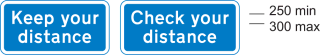 | |||
| 50 | Diagram 2933 Drivers should keep a distance of two chevron markings (the markings provided for at item 34 of the table in Part 4) from the vehicle in front | 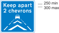 | |||
| 51 | Diagrams 2032 and 2130 Primary route (2032) or non‑primary route (2130) forming part of a ring road | 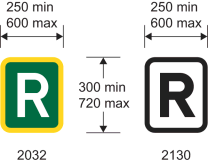 | |||
| 52 | Diagram 972 Stopping place for buses used for carrying tourists to allow passengers to take photographs |  | 17, 34 | 5 | 2 |
| 53 | Diagram 857A Information for pedestrians about tourist destinations and leisure facilities in a nearby place or area |  | 18, 19 | 5 | |
| 54 | Diagram 857B Information for pedestrians about tourist destinations and leisure facilities in a nearby place or area |  | 18 | 5 | |
| 55 | Diagram 2501 Distance to a parking place ahead |  | 1, 5(1) | ||
| 56 | Diagram 801 Parking place |  | |||
| 57 | Diagram 2713.1 Distance ahead to emergency telephone in a parking place or emergency lay‑by (Alternative types) |  | 1, 2, 5 | ||
| 58 | Diagram 2713 Direction to nearest emergency telephone on same side of the road(diagram shows blue background – for use on motorways) (Alternative types) | 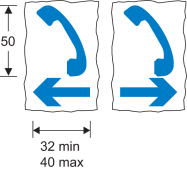 | 53 | 5 | |
| 59 | Diagram 2714 Side of emergency telephone box (Alternative types) |  | 29, 55 | 2, 6 | |
| 60 | Diagram 2715 Back of emergency telephone box (Alternative types) |  | 29, 55 | 2, 6 | |
| 61 | Diagram 2718 Route number and location reference |  | 29 | ||
| 62 | Diagram 2712 Location of fire rendezvous point (Alternative types) |  | 20 | 5 | |
| 63 | Diagram 878 Area in which enforcement cameras are in use (Alternative types) |  | 21 | ||
| 64 | Diagram 880 Speed camera ahead on a lit road and reminder of 30 mph speed limit | 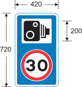 | 21(2) | ||
| 65 | Diagram 880.1 Speed camera ahead on an unlit road and reminder that a national speed limit applies | 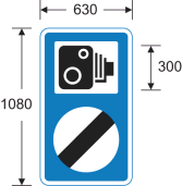 | 21(2) | ||
| 66 | Diagrams 827.1, 827.2 and 827.3 Hospital ahead | 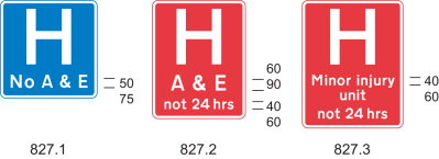 | 22 | ||
| 67 | Diagram 775 Vehicular traffic must not stop within the area of a railway or tramway level crossing |  | |||
| 68 | Diagram 783 Drivers of long low, large or slow vehicles must telephone to obtain permission before using a railway or tramway level crossing (Alternative types) |  | |||
| 69 | Diagram 785.1 Name of level crossing and details of telephone number for contacting railway or tramway operator | 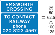 | 23 | ||
| 70 | Diagram 786 Place where large, slow or long low vehicles should wait near a railway or tramway level crossing while the driver obtains permission by telephone to cross or confirms he or she has crossed (Alternative types) |  | 56 | ||
| 71 | Diagram 787 Site of telephone or emergency telephone at or near a railway or tramway level crossing (Alternative types) |  | |||
| 72 | Diagram 788 Direction to telephone or emergency telephone at or near a railway or tramway level crossing (Alternative types) | 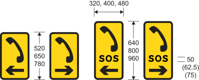 | |||
| 73 | Diagram 611 Vehicular traffic may reach the same destination by proceeding either side of the sign | 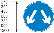 | 1, 4 | 1 | |
| 74 | Diagrams 833, 834, 835 and 836 Signs regulating the movement of vehicular traffic into and out of premises with more than one access to a road | 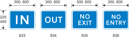 | 5 | ||
| 75 | Traffic mirror for providing additional visibility (not for use with traffic signals) | The mirror must be convex and any frame must be of a single colour, being black, grey, yellow or white | 13 | ||
| 76 | Diagram 970 Stopping place for buses |  | 30, 31, 34 | 5 | 2 |
| 77 | Diagrams 973.2 and 973.3 Stopping place for buses operated by or on behalf of, or under agreement with, Transport for London |  | 30, 32, 34 | 5 | 2 |
| 78 | Diagram 971 Stopping place for tramcars |  | 30, 33, 34 | 5 | 2 |
| 79 | Diagram 2928 Motorway sign indicating the boundary of an administrative area, a ceremonial area or an historic county area (Alternative types) |  | 35 | ||
| 80 | Diagram 2401 Primary or non‑primary route sign indicating the boundary of an administrative area, a ceremonial area or an historic county area |  | 30, 36 | 5 | |
| 81 | Diagram 2402.1 Primary or non‑primary route sign indicating the name of a city, town or village commencing immediately ahead (Alternative types) | 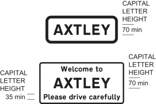 | 37 | 5 | 3 |
| 82 | Diagram 2403.1 Primary or non-primary route sign indicating the name of a city, town or village immediately ahead, together with extra local information |  | 30, 38 | 5 | 4 |
| 83 | Diagram 2404 Primary or non-primary route sign indicating the name of a city, town, village, an administrative area, a ceremonial area or an historic county area immediately ahead, together with phrase and image that is representative of the city, town, village or area |  | 39 | 5 | 4 |
| 84 | Diagram 976 Maximum speed limit for tramcars in kilometres per hour |  | 40 | 5 | |
| 85 | Diagram 864.2 Vehicle testing station approved by the Driver and Vehicle Standards Agency |  | 58 | 5 | |
| 86 | Diagram 865 Motor cycle test centre |  | 5 |
PART 3Provisions applicable to markings in Part 4
1. The warning or information of a description in column 2 of an item in the Part 4 sign table must be conveyed by road markings that are—
(a)of the colour and type; and
(b)comply with the requirements as to size,
shown in the diagram in the same column of the item, or that diagram as varied in accordance with column 3 (by reference to paragraphs in Part 5).
2. A provision of Part 6 mentioned (by reference to paragraph number) in column 4 of an item in the Part 4 sign table applies to the marking provided for at that item.
3. A reference to a “longitudinal marking” is to a marking placed on the carriageway of a road longitudinally to the flow of traffic.
PART 4Advisory road markings
Sign table — Schedule 11, Part 4
(1) Item | (2) Description and diagram | (3) Permitted or required variants in Part 5 | (4) Requirements applicable in Part 6 |
|---|---|---|---|
| 1 | Diagram 1003.1 Vehicular traffic approaching a roundabout should give way at or immediately beyond the line to vehicular traffic circulating on the carriageway of the roundabout  | 7 | |
| 2 | Diagram 1004 Vehicular traffic should not cross or straddle the line unless it is safe to do so and when the line is used to indicate a cycle lane, motor vehicles should not enter that lane unless it is clear of pedal cycles (Longitudinal marking)  | 57 | 7, 8, 10, 12 |
| 3 | Diagram 1004.1 Vehicular traffic should not cross or straddle the line unless it is safe to do so and when the line is used to indicate a cycle lane, motor vehicles should not enter that lane unless it is clear of pedal cycles (Longitudinal marking)  | 7, 8, 10, 12 | |
| 4 | Diagram 1005 Division of carriageway into traffic lanes on part of the carriageway where vehicles normally proceed in the same direction other than at places where the marking at item 2 of this table is used (Longitudinal marking)  | 7, 8, 10, 12 | |
| 5 | Diagram 1005.1 As the marking at item 4 other than at places where the marking at item 3 is used (Longitudinal marking)  | 7, 8, 10, 12 | |
| 6 | Diagram 1008 Division between opposing flows of traffic on a carriageway other than at places where the marking at item 2 is used (Longitudinal marking)  | 57 | 7, 8, 10, 12 |
| 7 | Diagram 1008.1 Division between opposing flows of traffic on a carriageway other than at places where the marking at item 3 is used (Longitudinal marking)  | 7, 8, 10, 12 | |
| 8 | Diagram 1009A Edge of the carriageway at a road junction, exit from a private drive onto a public road, or the start of a cycle lane (Longitudinal marking)  | 7 | |
| 9 | Diagram 1009B Edge of the carriageway at a junction of a cycle track and another road (Longitudinal marking)  | ||
| 10 | Diagram 1010 (a) edge of the carriageway at a road junction or a lay-by, or at an exit from a private drive onto a public road; (b) the start of a traffic lane, the boundary of which is indicated by the road marking shown at item 11 of the table in Part 6 of Schedule 9; (c) when used in conjunction with the road marking at item 4 of the sign table in Part 4 of Schedule 2, the most suitable path to be taken by high vehicles under a low bridge or to avoid an overhanging structure; (d) when laid alongside rails used by tramcars, the edge of the part of the carriageway used by the tramcars; (e) the division between the main carriageway and a traffic lane which leaves the main carriageway at a junction ahead; (f) the boundary between the main carriageway and either a diverging or merging traffic lane at a road junction; (g) the boundary between an emergency refuge area and either an actively managed hard shoulder or the edge of carriageway of a motorway; or (h) the division between the main carriageway and a cycle lane through a junction (Longitudinal marking)  | 41 | 7, 8, 11, 12 |
| 11 | Diagram 1012.1 (a) edge of the carriageway available for through traffic other than at a road junction, an exit from a private drive onto a public road, lay-by or emergency refuge area; (b) the back edge of a hard shoulder; (c) the edge of a footway where it passes over a railway or tramway level crossing; or (d) the boundary between the carriageway of a motorway and an actively managed hard shoulder (Longitudinal marking)  | 7, 9, 11, 12 | |
| 12 | Diagram 1012.2 (a) edge of carriageway of a motorway other than at an emergency refuge area or a junction with a slip road; or (b) the back edge of an actively managed hard shoulder; and, in both cases, incorporating an audible and tactile warning (Longitudinal marking)  | 42 | 3, 7, 9, 11, 12 |
| 13 | Diagram 1012.3 Edge of carriageway of a road that is not a motorway and which has hard strips or hard shoulders, other than at a junction with a slip road, and incorporating an audible and tactile warning (Longitudinal marking)  | 43 | 3, 7, 9, 11, 12 |
| 14 | Diagram 1014 (a) Direction in which vehicular traffic should pass a road marking shown at item 7, 11 or 23 of the sign table in Part 6 of Schedule 9 or at item 23, 24 or 25 of the sign table in Part 4 of this Schedule; (b) obstruction on the carriageway ahead; (c) reduction in the number to traffic lanes in the carriageway ahead; or (d) path to be taken by vehicular traffic to avoid a route available for tramcars only (Longitudinal marking) (Alternative types)  | 7 | |
| 15 | Diagram 1024 Vehicular traffic should proceed with caution because of potential danger ahead  | 7 | |
| 16 | Diagram 1026 Part of the carriageway which should be kept clear of stationary vehicles (Alternative types)  | ||
| 17 | Diagram 1026.1 Part of the carriageway outside a vehicular entrance to adjacent premises or a private drive, or where the kerb is dropped to provide a convenient crossing place for pedestrians, which should be kept clear of waiting vehicles  | ||
| 18 | Diagram 1029 Direction in which pedestrians should look for approaching traffic  | 44 | |
| 19 | Diagram 1035 Appropriate traffic lanes for different destinations (Alternative types)  | 45 | |
| 20 | Diagram 1038 Appropriate traffic lanes for different manoeuvres (Longitudinal marking) (Alternative types)  | ||
| 21 | Diagram 1038.1 Appropriate direction to be taken by traffic turning within a junction (Alternative types)  | 46 | |
| 22 | Diagram 1039 Place where traffic streams divide or bifurcate (Longitudinal marking) (Alternative types)  | 7 | |
| 23 | Diagram 1040 Part of the carriageway which vehicular traffic should not enter unless it is seen by the driver to be safe to do so (Alternative types)  | 47 | 7, 8, 10, 12 |
| 24 | Diagram 1040.3 Reduction in the number of lanes, or area not available to traffic, on the main carriageway or slip road of a motorway or all-purpose dual carriageway road 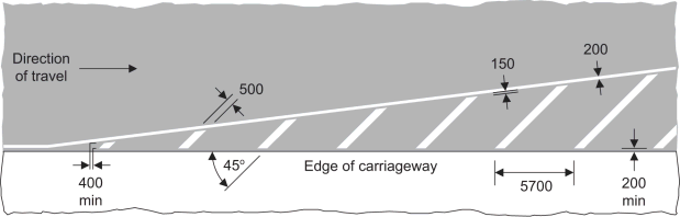 | 48 | 7, 8, 11, 12 |
| 25 | Diagram 1040.4 Part of the carriageway adjacent to the edge which vehicular traffic should not enter unless it is seen by the driver to be safe to do so  | 49 | 7, 8, 11, 12 |
| 26 | Diagram 1040.5 End of a hard shoulder 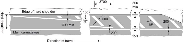 | 50 | 7, 8, 11, 12 |
| 27 | Diagram 1041 Part of the carriageway where vehicular traffic passes in the same direction on both sides of the marking, and should not enter the area covered by the marking unless it is seen by the driver to be safe to do so (Alternative types)  | 51 | 7, 8, 11, 12 |
| 28 | Diagram 1057 Cycle lane, track or route (Alternative types)  | ||
| 29 | Diagram 1057.1 Number of a cycle route (Alternative types)  | 29 | |
| 30 | Diagram 1058 End of a cycle lane, track or route  | ||
| 31 | Diagram 1058.1 Pedal cycles should proceed with caution because of potential danger ahead  | ||
| 32 | Diagram 1059 Directions in which pedal cycles should travel along a cycle lane, track or route (Alternative types)  | ||
| 33 | Diagram 1062 Road hump  | 7 | |
| 34 | Diagram 1064 Marking used in conjunction with the sign shown at item 50 of the sign table in Part 2 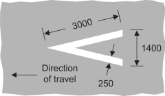 | 7 | |
| 35 | Diagram 1067 Transverse yellow bar markings for use only on approaches to roundabouts on motorways and dual carriageway roads subject to the national speed limit, either on the main carriageway or on an exit slip road  | 52 | 14, 15 |
| 36 | Diagram 1066 Edge of part of the road used by tramcars (Longitudinal marking)  |
PART 5Permitted variants of the signs in Parts 2 and 4
1. A distance may be added or varied, but, in relation to the signs provided for at items 11 and 16 in the Part 2 sign table, the distance must not exceed two miles.
2. The distance may be omitted and, if shown in a separate panel on the sign with no other legend, the panel must be omitted.
3. The distance may be replaced by an arrow pointing horizontally to the left or to the right.
4. The symbol, or all symbols together, may be reversed in a mirror image.
5.—(1) An arrow pointing horizontally to the left or to the right may be added or reversed.
(2) The arrow may be omitted.
6. Symbols and arrows indicating the road layout may be varied.
7. The blue panel need not extend to the edge of the nameplate and the black border may be omitted.
8. The name of the tunnel and the indication of the length may be varied.
9. The legend “Except buses” may be omitted or varied to “Bus lane”, “Except cycles” or “Except buses & cycles”; the number of lanes may be varied and any arrow may indicate two directions and point horizontally to the left and ahead, horizontally to the right and ahead or horizontally to the left and to the right.
10. The time period may be varied in accordance with Part 1 of Schedule 18, or omitted and where the times are shown in a separate panel on the sign, the panel must be omitted when the times are so omitted.
11. The local bus symbol may be varied to the bus symbol shown at item 40 of the sign table in Part 2 of this Schedule.
12. The permitted variants are—
(a)the arrow and cycle symbol may be reversed (if both are reversed);
(b)“lane” may be varied to “track” in which case the arrow may be omitted and the symbol reversed;
(c)“lane” may be varied to “lanes” or “tracks” in which case the arrow must be omitted and the cycle symbol reversed.
13. “Authorised vehicles” and symbols, other than the bus symbol, may be omitted as appropriate.
14. The continuous line and the broken line may be varied to accord with the layout of the road markings—
(a)at item 10 of the sign table in Part 4 of this Schedule and item 11 of the sign table in Part 6 of Schedule 9 when placed to indicate the extent of a bus lane; or
(b)at item 8 of the sign table in Part 4 of this Schedule and item 7 of the sign table in Part 6 of Schedule 9 when placed to indicate the extent of a cycle lane.
15. The words “LANE” and “LANES” may be varied to “TRACK”.
16. The number of taxis may be varied as appropriate and information relating to the taxi services from that rank may be shown in the white space in lettering of any colour with letter height not exceeding 25 mm, or the white space may be omitted.
17. The time period may be omitted or varied in accordance with Part 1 of Schedule 18 and the face of the sign may be curved.
18.—(1) The white area is to be filled with maps or a legend in any colour with lettering of any colour.
(2) The x-height of a legend referred to in sub-paragraph (1) must not exceed 25 mm.
(3) The “i” symbol may be omitted.
(4) The sign may have more than one panel or side if each is of the design prescribed in the diagram.
19. The logo of a local tourist organisation may be added at the top of the sign.
20. The legend “No.1” may be varied to another number, a letter or a compass point.
21.—(1) The legend may be omitted or varied to “Speed cameras”, “Average speed check”, “Traffic signal and speed cameras”, “Traffic enforcement cameras”, “Police cameras”, “Police enforcement cameras” or “Bus lane cameras”.
(2) The legend may include, or a legend may be added for, the name, and logo, of the enforcement authority.
22. “not 24 hrs” may be omitted.
23. The name or location of the crossing in the top panel may be varied as appropriate and may be displayed on any number of lines; “TO CONTACT RAILWAY” may be on one line; “RAILWAY” may be varied to “TRAM Co.” and the telephone number may be varied as appropriate.
24. Place names, street names or the name of a geographical area may be omitted or varied as appropriate and may be displayed on any number of lines.
25.—(1) Identification numbers of routes—
(a)may be varied and may include capital letters; and
(b)where indicating a route to which a particular route leads, may be shown in brackets.
(2) When a route (other than a national or regional cycle route) is indicated, the route number and background of the route number patch may be in any contrasting colours but, if the route number patch has a light background, the white edge must be omitted.
26. When placed on a primary route the sign must be varied so that—
(a)the background colour is dark green;
(b)the border, any legend and any symbol (other than a red bar) is white; and
(c)any red bar has a white edge.
27. When placed on a non-primary route the sign must be varied so that—
(a)the background colour is white; and
(b)the border, any legend and any symbol is black.
28. When placed on a motorway the sign must be varied so that—
(a)the background colour is blue;
(b)the border, any legend and any symbol (other than a red bar) is white; and
(c)any red bar has a white edge.
29. The reference or identification number and any route number may be varied as appropriate.
30. Letters, numerals and other characters incorporated into the sign need not comply with the requirements of Schedule 17.
31.—(1) The bus symbol may be omitted.
(2) “Request” may be inserted before “Bus Stop”.
(3) “Stop” may be varied to “Stand”.
(4) “Bus Stop” may be varied to “Request Stop” when the bus symbol is shown.
(5) The legend may be in capital letters.
(6) The background, symbol and lettering may be in any contrasting colours.
(7) The face of the sign may be curved.
32. ”BUS STOP” may be varied to “BUS STAND” and the face of either sign may be curved.
33. ”Tram” may be varied to “Request” and the face of the sign may be curved.
34. Supplementary plates may be added to the sign to give additional information such as bus routes numbers, the name of the stopping place or boarding point and a reference to a telephone enquiry line.
35.—(1) The place name may be varied.
(2) Arms or a logo may be added, together with one of the following—
(a)a message of welcome;
(b)a phrase denoting the ceremonial or historic nature of the area; or
(c)a phrase denoting an item of local geographical or historical interest,
where the phrase provided for at (a), (b) or (c) does not exceed three words.
(3) The place name may be varied to the name of a river, inland waterway or bridge.
36.—(1) The place name may be varied.
(2) The arms or logo may be omitted or varied.
(3) “Welcome to” may be omitted or varied to a similar phrase.
(4) The place name may be preceded by—
(a)“County of”;
(b)“Ceremonial County of”;
(c)“Historic County of”;
(d)a phrase provided for at paragraphs (a) to (c) preceded by “Welcome to the” or similar phrase (and for the purposes of this paragraph “ceremonial” and “historic” may be used instead of “Ceremonial” and “Historic”).
and a reference to “County” may be replaced by a reference to the appropriate administrative or ceremonial area.
(5) The place name may be followed by—
(a)“County Council”; or
(b)“County Council welcomes you” or a similar phrase,
and a reference to “County Council” may be replaced by a reference to the appropriate authority for the administrative area.
(6) A phrase denoting an item of local, geographical or historical interest may be added.
(7) A reference to not more than two places outside the United Kingdom with which the place is twinned may be added.
(8) In Scotland, the Scottish Gaelic equivalent of—
(a)the place name;
(b)“Welcome to”, or a similar phrase as provided for in sub-paragraph (3); and
(c)a phrase provided for at sub-paragraph (4),
may be used either in addition to, or instead of, the English version.
(9) The number of words in addition to the place name should not exceed eight.
(10) The legend, border and background may be in any contrasting colours except red.
(11) The border may be omitted.
(12) The shape and layout of the sign may be varied and the relative sizes of lettering on different parts of the sign may be varied provided the place name remains the most prominent feature.
37.—(1) The place name may be varied.
(2) “Welcome to” may be omitted or varied to a similar phrase.
(3) “City of” or “Welcome to the City of” may precede the place name.
(4) “Please drive carefully” may be omitted or varied to “Thank you for driving carefully” or another road safety message of not more than five words.
(5) In Scotland, the Scottish Gaelic equivalent of—
(a)the place name;
(b)“Welcome to” or a similar phrase; and
(c)“City of” or “Welcome to the City of”,
may be used either in addition to, or instead of, the English version.
(6) When “Welcome to” is omitted, a phrase denoting an item of local geographical or historical interest, including “Market town of” or similar, may be added above the place name provided the phrase does not exceed five words.
(7) The relative sizes of lettering on different parts of the sign may be varied provided the place name remains the most prominent feature.
38.—(1) The place name may be varied as appropriate.
(2) The arms may be omitted, varied as appropriate, or varied to a logo or symbol indicating a local landmark or historical feature.
(3) The district council name may be omitted or varied to a name of an appropriate authority.
(4) “Welcome to” may be omitted or varied to a similar phrase.
(5) The legend “City of” or “Welcome to the City of” may precede the place name.
(6) The place name may be varied to the name of—
(a)a river, inland waterway or bridge;
(b)a National Park;
(c)in England and Wales, an area of outstanding natural beauty designated as such under section 82 of the Countryside and Rights of Way Act 2000(69); or
(d)in Scotland, a National Scenic Area designated as such under section 263A of the Town and Country Planning (Scotland) Act 1997(70).
(7) In Scotland, the Scottish Gaelic equivalent of—
(a)the place name;
(b)“Welcome to” or a similar phrase; and
(c)“City of” and “Welcome to the City of”,
may be used either in addition to, or instead of, the English version.
(8) The symbols on the brown panel may be varied to any of those shown in Parts 14 to 18 of Schedule 12, but must not exceed three in number.
(9) The symbols and brown panel may be omitted.
(10) “Please drive carefully” may be omitted or varied to “Thank you for driving carefully” or another road safety message.
(11) A phrase denoting an item of local geographical or historical interest, including “Market town of” or similar, may be added.
(12) “Twinned with” may be varied to “Twin town” or “Twin towns”.
(13) The name of the twin town may be varied.
(14) The names of additional twin towns may be added.
(15) Flags, arms or logos associated with the twin towns may be added.
(16) The reference to twin towns may be omitted.
(17) The legend, border and background other than the brown panel and its symbols, may be in any contrasting colours except red.
(18) The border may be omitted.
(19) The shape and layout of the sign may be varied and the relative sizes of lettering on different parts of the sign may be varied provided the place name remains the most prominent feature.
39.—(1) The place name may be varied as appropriate.
(2) “Welcome to” may be omitted or varied to “City of” or a similar phrase of not more than three words, or five words when “The Flower City” is omitted after the place name.
(3) “The Flower City” may be omitted or varied to a similar phrase of not more than three words, or five words when “Welcome to” is omitted before the place name.
(4) In Scotland, the Scottish Gaelic equivalent of—
(a)the place name;
(b)“Welcome to” and “City of” or similar phrase may be used either in addition to, or instead of, the English version.
(5) The relative sizes of lettering on different parts of the sign may be varied provided the place name remains the most prominent feature.
40.—(1) Subject to sub-paragraph (2) the numeral “30” may be varied or may be substituted by other information and the background, border and any symbols and characters may be in any colour.
(2) The variations referred to in sub-paragraph (1) are not permitted to the extent that they would not be in accordance with the exercise of any functions by the Office of Rail and Road.
41.—(1) An audible or tactile warning in the form of a raised rib may be incorporated into the white parts of the marking, in the manner shown at item 12 of the sign table in Part 4 of this Schedule, when the marking is used to delineate the boundary between an emergency refuge area and an actively managed hard shoulder.
(2) Ribs on an individual white mark must be 250 mm apart.
42. The notch may be omitted from the raised rib and the width of the line must be varied to 150 mm when it is used to delineate the back edge of an actively managed hard shoulder.
43. The notch may be omitted from the raised rib and the width of the line must be 200 mm when used on roads with hard shoulders.
44. When used in circumstances other than shown in the diagram the marking must be varied to accord with the direction of approaching traffic.
45. Route numbers and place names may be varied as appropriate but the words “turn left”, “ahead” or “turn right” must not be included in the marking; arrows may be omitted.
46. The curvature of the arrow may be varied.
47. One of the boundary lines must be omitted when—
(a)the marking is placed alongside the marking at item 7 or 11 of the sign table in Part 6 of Schedule 9 denoting a cycle lane or bus lane respectively; or
(b)the marking is placed alongside the marking shown in diagram A at item 23 of the sign table in Part 6 of Schedule 9 indicating to vehicular traffic the requirements in paragraph 9 in Part 7 of that Schedule.
48. The width of the longitudinal line may be varied to 150 mm when used on an all-purpose road without hard shoulders and the boundary line may be replaced by the marking shown in the diagram at item 12 or 13 of the sign table in Part 4.
49.—(1) The marking may be used on the off side edge of the carriageway with the angle of the hatching reversed.
(2) The boundary line must be omitted when the marking is placed alongside the marking shown in the diagram at item 7 or 11 of the sign table in Part 6 of Schedule 8, denoting a cycle lane or bus lane respectively.
50. The boundary line and edge of carriageway line may be replaced by the marking shown in the diagram at item 12 or 13 of the sign table in Part 4 of this Schedule varied to 200 mm wide.
51.—(1) The direction of the chevrons must be reversed when the direction of travel is in the opposite direction.
(2) One of the boundary lines must be omitted when the marking is placed alongside the marking provided for at item 7 or 11 of the sign table in Part 6 of Schedule 8, denoting a cycle lane or bus lane respectively.
52. The distance between each end of each bar to the edge of the carriageway or the edge line may be increased to a maximum of 750 mm.
53. The colour of the telephone symbol and arrow must be varied so that they are—
(a)black if the road is a non‑primary route; or
(b)dark green if the road is a primary route.
54. The wheelchair symbol may be omitted and the width of the sign reduced to 300 mm.
55. The permitted variants are—
(a)the relative position of the number and “SOS” may be reversed;
(b)a flashing white light may be added to the sign.
56. ”AND USE PHONE” may be varied to “AND USE SOS PHONE” or “& USE SOS PHONE”.
57. The width of the line may be 50 mm when the marking is placed on a cycle track.
58. ”The Driver and Vehicle Standards Agency” may be varied to—
(a)“DVSA”; or
(b)the name of a successor organisation to the Driver and Vehicle Standards Agency (in respect of its function of approving testing centres) or an acronym for that successor organisation.
PART 6Requirements applying to signs in Parts 2 and 4
1. Where the sign is placed temporarily on a road by a constable or person acting under the instructions (whether general or specific) of the chief officer of police in connection with a temporary statutory provision, the diameter may be reduced to not less than 200 mm.
2. The letters and numerals in the first diagram must have the proportions and form shown in Part 1 of Schedule 17.
3. The road marking must not project above the surface of the adjacent carriageway by more than 6 mm except for the raised ribs which may project above the surface of the remainder of the marking by not more than the maximum dimension indicated on the lower part of the diagram illustrating the side elevation of the marking.
4.—(1) Subject to sub-paragraphs (2) and (3), where the sign is erected on a road subject to a speed limit greater than 20 mph and is within 50 metres of any lamp which forms part of a system of street-lighting, the illumination requirements for the sign are–—
(a)where that system of street-lighting is illuminated throughout the hours of darkness, the sign must be illuminated by internal or external lighting and may also be reflectorised; or
(b)where that system of street-lighting is not illuminated throughout the hours of darkness—
(i)the sign must be illuminated by internal or external lighting for so long as that system is illuminated and must also be reflectorised; or
(ii)the sign must be illuminated throughout the hours of darkness by internal or external lighting for so long as that system is illuminated and may also be reflectorised.
(2) Sub-paragraph (1) does not apply to a sign mounted on a self-righting bollard.
(3) Where the sign is mounted on a bollard fitted with a means of lighting it internally, the sign must be illuminated throughout the hours of darkness by that means of internal lighting.
5. The sign need not be illuminated.
6. The parts of the sign coloured orange and white must be reflectorised and the parts of the sign coloured orange may also be fluorescent.
7. The marking must be reflectorised.
8. Studs incorporating—
(a)reflectors;
(b)retroreflecting material;
(c)a light source which emits a steady light during the hours of darkness; or
(d)any combination,
may be used with the road marking provided they are placed in the gaps between parts of a broken line, or alongside a solid line.
9. Studs incorporating—
(a)reflectors;
(b)retroreflecting material;
(c)a light source which emits a steady light during the hours of darkness; or
(d)any combination,
may be used with the road marking provided they are placed at the side of, and adjacent to, the line shown in the diagram.
10. The light reflected by the reflectors or retroreflecting material, or emitted by the light source, from a stud must be white.
11. The light reflected by the reflectors or reflecting material, or emitted by the light source, from a stud must be—
(a)red—
(i)when placed in conjunction with the marking shown at item 27 of the table in Part 4 of this Schedule, as viewed in the direction of travel;
(ii)when placed in conjunction with a road marking to indicate the nearside, as viewed in the direction of travel, edge of the carriageway of any road, except a motorway alongside which there is an actively managed hard shoulder; or
(iii)when placed in conjunction with the marking at item 11 in the table in Part 4 of this Schedule, to indicate the boundary between the carriageway of a motorway and an actively managed hard shoulder;
(b)amber, to indicate the off side edge of a carriageway which—
(i)is contiguous to a central reservation or to traffic cones or cylinders at road works or to the road marking at item 24 of the table in Part 4 of this Schedule; or
(ii)carries traffic in one direction only; and
(c)green, when placed in conjunction with a road marking at item 10 of the table in Part 4 of this Schedule, where the edge of any part of the carriageway available for through traffic at a junction, a lay-by or a parking place is so indicated to drivers of approaching vehicles.
12. The external part of a stud that is visible when the stud is placed must be—
(a)the colour of the reflectors or retroreflecting material (where used);
(b)white;
(c)of a natural metallic finish;
(d)of another neutral colour;
(e)clear; or
(f)any combination,
but when the stud is in place temporarily during road works it must be fluorescent green-yellow except to the extent it consists of reflectors or retroreflecting material necessary to reflect the colour required under paragraph 10 or 11 or it is necessary for it to be a different colour or clear in order for the stud to emit, by a light source, the colour of light required under paragraph 10 or 11.
13. Any frame used must not be reflectorised.
14.—(1) When placed on the main carriageway, the leading edge of each bar marking must be placed at the appropriate distance specified in the table below.
(2) For the purposes of this paragraph—
(a)each bar marking is referred to in the table below by the capital letter D followed by a number;
(b)a bar marking is placed at the appropriate distance specified in the table below if the distance between the point at which the leading edge of the marking is placed and the point at which the leading edge of bar marking D1 is placed is the distance specified in relation to the marking in the table; and
(c)the distance specified in relation to a bar marking is the distance in metres which appears immediately below the reference to the bar marking in the table below.
| Bar no. | D2 | D3 | D4 | D5 | D6 | D7 | D8 | D9 | D10 | D11 | D12 | D13 | D14 | D15 | |
| Distance to D1 (m) | 2.75 | 5.50 | 8.25 | 11.05 | 13.90 | 16.80 | 19.70 | 22.60 | 25.55 | 28.55 | 31.60 | 34.65 | 37.70 | 40.80 | |
| Bar no. | D16 | D17 | D18 | D19 | D20 | D21 | D22 | D23 | D24 | D25 | D26 | D27 | D28 | D29 | D30 |
| Distance to D1 (m) | 43.95 | 47.15 | 50.35 | 53.55 | 56.80 | 60.10 | 63.45 | 66.80 | 70.15 | 73.60 | 77.05 | 80.55 | 84.10 | 87.65 | 91.30 |
| Bar no. | D31 | D32 | D33 | D34 | D35 | D36 | D37 | D38 | D39 | D40 | D41 | D42 | D43 | D44 | D45 |
| Distance to D1 (m) | 94.95 | 98.65 | 102.40 | 106.15 | 110.00 | 113.85 | 117.75 | 121.70 | 125.65 | 129.70 | 133.75 | 137.85 | 142.00 | 146.15 | 150.40 |
| Bar no. | D46 | D47 | D48 | D49 | D50 | D51 | D52 | D53 | D54 | D55 | D56 | D57 | D58 | D59 | D60 |
| Distance to D1 (m) | 154.65 | 158.95 | 163.35 | 167.75 | 172.25 | 176.75 | 181.30 | 185.95 | 190.60 | 195.35 | 200.10 | 204.90 | 209.80 | 214.70 | 219.70 |
| Bar no. | D61 | D62 | D63 | D64 | D65 | D66 | D67 | D68 | D69 | D70 | D71 | D72 | D73 | D74 | D75 |
| Distance to D1 (m) | 224.70 | 229.80 | 234.90 | 240.10 | 245.40 | 250.70 | 256.10 | 261.50 | 267.00 | 272.60 | 278.20 | 283.90 | 289.60 | 295.45 | 301.30 |
| Bar no. | D76 | D77 | D78 | D79 | D80 | D81 | D82 | D83 | D84 | D85 | D86 | D87 | D88 | D89 | D90 |
| Distance to D1 (m) | 307.25 | 313.90 | 319.35 | 325.55 | 331.75 | 338.15 | 344.65 | 351.35 | 358.30 | 365.50 | 373.20 | 380.90 | 388.60 | 396.25 | 403.95 |
15.—(1) When placed on a slip road, the leading edge of each bar marking must be placed at the appropriate distance specified in the table below.
(2) For the purposes of this paragraph—
(a)each bar marking is referred to in the table below by the capital letter D followed by a number;
(b)a bar marking is placed at the appropriate distance specified in the table below if the distance between the point at which the leading edge of the marking is placed and the point at which the leading edge of bar marking D1 is placed is the distance specified in relation to the marking in the table;
(c)the distance specified in relation to a bar marking is the distance in metres which appears immediately below the reference to the bar marking in the table below.
| Bar no. | D2 | D3 | D4 | D5 | D6 | D7 | D8 | D9 | D10 | D11 | D12 | D13 | D14 | D15 | |
| Distance to D1 (m) | 2.75 | 5.55 | 8.45 | 11.35 | 14.35 | 17.40 | 20.50 | 23.70 | 26.90 | 30.20 | 33.55 | 37.00 | 40.50 | 44.05 | |
| Bar no. | D16 | D17 | D18 | D19 | D20 | D21 | D22 | D23 | D24 | D25 | D26 | D27 | D28 | D29 | D30 |
| Distance to D1 (m) | 47.70 | 51.45 | 55.30 | 59.20 | 63.15 | 67.20 | 71.35 | 75.60 | 79.90 | 84.30 | 88.80 | 93.45 | 98.20 | 103.00 | 107.90 |
| Bar no. | D31 | D32 | D33 | D34 | D35 | D36 | D37 | D38 | D39 | D40 | D41 | D42 | D43 | D44 | D45 |
| Distance to D1 (m) | 112.90 | 118.00 | 123.30 | 128.70 | 134.20 | 139.80 | 145.50 | 151.35 | 157.40 | 163.60 | 170.00 | 176.70 | 183.90 | 191.60 | 199.30 |
PART 7The Schedule 11 General Directions
1. Where the sign is mounted on a bollard—
(a)the bollard must—
(i)be illuminated by means of internal lighting; and
(ii)conform to British Standard BS EN 12899-2:2007(71); or
(b)in the case of a self-righting bollard, the bollard—
(i)must be illuminated by the use of retroreflecting material; and
(ii)conform to British Standard BS 8442:2015(72).
2. The back of the sign may be of any colour.
3.—(1) Sub-paragraph (2) applies in relation to a yellow backing board.
(2) Where the sign is placed on the same backing board as the maximum speed limit sign, the backing board may be of any shape.
4. Where the sign is placed on a backing board, no other sign may be included on the same board.
Regulation 3, Direction 3
SCHEDULE 12Directional signs
PART 1General provisions applying to Parts 2 to 20
1. Information of a description in column 2 of a sign table in Parts 3, 5, 7, 9, 11, 12, 14, 15, 16, 17, 18, or 20 of this Schedule, or a combination of any such descriptions, must be conveyed by a sign (a “directional sign”) consisting of the legend or symbol, or a combination, provided for in respect of that description or descriptions in accordance with the provisions of this Part and Parts 2 to 20 on an appropriate background.
2. Subject to paragraph 4, an appropriate background for a sign of a description specified in column 2 of an item in the Part 2 sign table is one of the colour and type shown in either diagram A or B of the item.
3. A legend on a directional sign must be of a height provided for in column 4 of the Part 2 sign table (unless in relation to a particular legend it is provided elsewhere that the legend is to be a different height) and the sign must be of a size appropriate to accommodate its elements (including any legend).
4. An appropriate background may differ from diagram A or B in that—
(a)a diagram A sign background may be divided into separate panels;
(b)a diagram B sign background may be reversed to point to the left; and
(c)the background at item 8 or 9 of the sign table in Part 2 (signs for cyclists and pedestrians respectively) may be varied in accordance with column 4 at that item.
5. Where a sign indicates a road or route and that road or route is temporarily closed, a board coloured red and displaying in white lettering the words “Road temporarily closed” or “Route temporarily closed” may be fixed to the sign, or to that part of the sign where that road or route is indicated, in order to cancel temporarily the indication.
6.—(1) A sign with a background provided for at item 5, 8 or 9 of the Part 2 sign table need not be illuminated.
(2) Sub-paragraph (1) does not apply to a sign with an item 5 background when placed on a motorway or if the sign—
(a)gives directions to a leisure facility of a description at item 5, 6, 7, 10, 11 or 12 of the Part 14 sign table; or
(b)includes the legend “Tourist hostel”.
7. A directional sign which only conveys directions to a telephone or public toilets (or both) need not be illuminated.
8. Where a diagram A sign with a background provided for at item 1 in the Part 2 sign table is mounted above the carriageway of a motorway within 50 metres of any lamp which forms part of a system of street-lighting, the illumination requirements for the sign are—
(a)where that system of street-lighting is illuminated throughout the hours of darkness, the sign must be illuminated by internal or external lighting for so long as that system is illuminated and may also be reflectorised; or
(b)where that system of street-lighting is not illuminated throughout the hours of darkness—
(i)the sign must be illuminated by internal or external lighting for so long as that system is illuminated or and must also be reflectorised, or
(ii)the sign must be illuminated throughout the hours of darkness by internal or external lighting and may also be reflectorised.
PART 2Sign background for directional signs for motorways, primary routes, non-primary routes, cyclists and pedestrians
Sign table — Schedule 12, Part 2
(1) Item | (2) Description | (3) Sign background | (4) Height of legend and variants |
|---|---|---|---|
| 1 | Sign placed on or near a motorway or placed on or near another road at a junction indicating a route leading directly to a motorway (Type A and B) |  | An x-height that is not less than 100 mm and not more than 400 mm |
| 2 | Sign placed on or near a primary route (Type A and B) |  | An x-height that is not less than 50 mm and not more than 300 mm |
| 3 | Sign placed on or near a non-primary route (Type A and B) |  | An x-height that is not less than 50 mm and not more than 300 mm |
| 4 | Sign placed on a motorway, primary or non-primary route showing only parking place destinations (Type A and B) |  | An x-height that is not less than 50 mm and not more than 400 mm |
| 5 | Sign placed on a motorway, primary or non-primary route showing only tourist destinations or leisure facilities (Type A and B) |  | An x-height that is not less than 50 mm and not more than 400 mm |
| 6 | Sign placed on a primary or non-primary route showing only Ministry of Defence establishments (Type A and B) |  | An x-height that is not less than 50 mm and not more than 300 mm |
| 7 | Sign placed on a motorway, primary or non-primary route showing only recommended routes for goods vehicles ahead (Type A and B) |  | An x-height that is not less than 50 mm and not more than 400 mm |
| 8 | Sign placed on a road, other than a motorway, showing routes for cyclists (Type A and B) |  | 1. An x-height that is not less than 25 mm and not more than 60 mm 2. The background may be varied to brown when the sign shows only tourist destinations or leisure facilities |
| 9 | Sign placed on a road, other than on a motorway, showing routes for pedestrians or equestrians (Type A and B) | | 1. An x-height that is not less than 25 mm and not more than 60 mm 2. The background, border and any chevron, legend, symbol or logo may be in any contrasting colours 3. The border, chevron or both may be omitted 4. The shape of the pointed end of diagram B may be varied |
PART 3Legends that may be shown on signs in Part 2
1. Information of a description in column 2 of an item in the sign table in this Part must be conveyed on a directional sign by one or more of the legends in column 3 of that item on an appropriate background.
2. The inclusion of a legend is subject to such restrictions, and further descriptions, as are given in column 3 in respect of that legend and any restriction provided for is without prejudice to any provision elsewhere in this Schedule that provides that legends contained in Part 3 may be placed on a directional sign in a manner that does not comply with the restriction.
3.—(1) Any word forming part of a legend provided for in the sign table in this Part may be written—
(a)entirely in lower case letters;
(b)entirely in capital letters; or
(c)in a mixture of capital and lower case letters.
(2) Paragraph (1) does not apply where alternative provision for a word is made in the sign table in this Part.
4.—(1) This paragraph applies to a legend provided for in this Part in the following circumstances—
(a)the legend is the name of a place that is a city, town, village or tourist destination; and
(b)the directional sign on which the legend appears—
(i)has a background provided for at item 2, 3 or 5 of the sign table in Part 2; and
(ii)is placed on a road in Scotland (except when placed on a motorway).
(2) The name of the place may be written in Scottish Gaelic, in addition to English, provided the Scottish Gaelic version is shown above the English.
(3) Where the name is the same in English and Scottish Gaelic, it may be written only once on the sign in a manner which complies with the requirements of these Regulations applicable to a name written in—
(a)English; or
(b)Scottish Gaelic.
Sign table — Schedule 12, Part 3
(1) Item | (2) Description | (3) Legends, restrictions and connected provisions |
|---|---|---|
1 | Destination, direction or type of route | A legend provided for at entry 3 of this item must only be used on a sign with a background provided for at item 9 of the sign table in Part 2. 1. The name of— (a)a place, which may be followed by: “city centre”, “town centre”, “village” or “village centre”; (b)a geographical area; (c)the name of a road; (d)an airport, heliport, railway station, port, tunnel, bridge, crossing or other transport facility; (e)a local destination not covered by (a) to (d), which may include a generic description of a facility 2. ”City centre”, “Town centre”, “Village centre”, “Village only”, “Other routes”, “Other traffic”, “Local traffic only”, “Through traffic”, “Ring road” or “Non-motorway traffic” 3. ”Public Footpath”, “Footpath”, “Bridleway”, “Byway”, “Restricted Byway”, “Concessionary Path”, “Permissive Path” (or other appropriate description for conveying the direction of a public right of way, concessionary path or permissive path). That word or phrase may be followed by— (a)a place, area or destination mentioned at entry 1; or (b)“city centre”, “town centre”, “village” or “village centre”, whether or not immediately preceded by “to” 4. The additional identifiers of a destination, or a combination of identifiers, mentioned at entry 5 may be added in brackets after— (a)a place, area or destination mentioned at entry 1 (including where used in an entry 3 legend); (b)a phrase mentioned at entry 2; or (c)“city centre”, “town centre”, “village” or “village centre” as referred to in an entry 3 legend 5. The additional identifiers are— (a)a compass point (“North”, “South”, “East” or “West”); (b)an abbreviated compass point (“N”, “S”, “E”, “W”, “NW”, “NE”, “SW” or “SE”); (c)“Central” or “C” (meaning “Central”); (d)“City”; (e)the name of an area that forms part of the destination to which the additional identifier relates and, where more than one identifier is used, they must be separated by a comma except that, where only two are used or to separate the final two identifiers, “&” must be used instead 6. ”only” may be added after— (a)a place, area or destination mentioned at entry 1(a) to (e) (including when used in an entry 3 legend); (b)a phrase mentioned at entry 2 (except “Village only” or “Local traffic only”); or (c)“city centre”, “town centre”, “village” or “village centre” as referred to in entry 3, and where any additional identifiers are used, “only” must come after them (and the bracket) 7. An indication that— (a)a footpath or other route mentioned in entry 3 is closed; (b)the direction of an alternative route where the footpath or other route is closed |
2 | Indication of alternative routes | A legend provided for at this item must only be used together with a legend provided for at item 1 or 3 of this table 1. “via toll road”, “via toll”, “via tunnel”, “via ferry” or “via” and the name of a destination or a route number 2. “unsuitable for” and one, or any appropriate combination, of the following— (a)“heavy goods vehicles”, (b) “HGVs”, (c) “long vehicles”, (d) “wide vehicles”, (e) “buses”, (f) “caravans”, (g) “trailers”, (h) “articulated vehicles” or (i) “light vehicles only”, with “and” inserted before the last legend where more than one is used 3. “alternative route” 4. “alternative route for” and one or any appropriate combination of the following— (a)“goods vehicles”, (b) “light vehicles only”, (c) “heavy vehicles”, (d) “HGVs”, (e) “high vehicles”, (f) “long vehicles”, (g) “wide vehicles”, (h) “buses”, (i) “caravans”, (j) “trailers”, (k) “articulated vehicles”, or (l) “prohibited vehicles”, with “and” inserted before the last where more than one is used 5. ”avoiding” and a place name or other destination, or one or any appropriate combination of the following— (a)“steep hill”; (b) “swing bridge”; (c) “lifting bridge”; (d) “low bridge”; (e) “weak bridge”; (f) “ford”; (g) “gated road”; (h) “toll road”; (i) “tunnel”; (j) “town centre”; (k) “level crossing”. The word “and” must be inserted before the last where more than one is used 6. “route for goods vehicles” or “route for non-motorway traffic” 7. “light vehicles only”
|
3 | Additional legends for signs showing only tourist destinations and leisure facilities | A legend provided for at this item may be used on its own or together with a legend provided for at item 1, 2, 5, 6 or 9 of this table but only on a background provided for at item 5, 8 or 9 of the Part 2 sign table 1. The name or generic description of an attraction or facility 2. The expression “Hotel”, “Hotels”, “B & B” or “Hotel and B & B” used as a generic description for overnight accommodation 3. “Youth Hostel” (but only when the hostel in question is controlled or approved by YHA (England and Wales)(73) or the Scottish Youth Hostels Association(74)) or “Tourist hostel” 4. The name of a city, town or village and, on a separate line, “historic market town” or other descriptive phrase provided that the x-height of the descriptive phrase is 80% of that used for the name of the city, town or village 5. “Country Tour”, or “Tour”, preceded by a place name or an appropriate description 6. “Tourist route to”, “Tourist trail to”, “Scenic route to”, “Scenic trail to”, “Coastal route to” or “Coastal trail to” and a destination 7. “Tourist route” or a route title |
4 | Route identification | A legend provided for in this item may be used on its own (except entries 7 and 8) or together with a legend provided for at item 1 of this table. A legend provided for at entries 1 to 7 may be placed on a background provided for at item 1, 2, 3 or 7 of the Part 2 sign table 1. Identification numbers of routes may be included on a directional sign; route numbers must be white on a blue or black background, yellow on a dark green background and black on a white background 2. A compass point (“North”, “South”, “East” or “West”) or an abbreviated compass point (“N”, “S”, “E”, “W”, “NW”, “NE”, “SW” or “SE”) may be added to the route number, shown in brackets in the same colour as the route number 3. Identification numbers of routes to which a particular route, with a different identification number, leads must be shown in brackets; a compass point (“North”, “South”, “East” or “West”) or an abbreviated compass point (“N”, “S”, “E”, “W”, “NW”, “NE”, “SW” or “SE”) may be added alongside the number within the same pair of brackets; where a route leads indirectly to a primary route and the route number of the primary route is the same as the route number of the non-primary route to be followed from the junction ahead, the number must be shown without any brackets 4. Superseded route numbers may be retained provided they are cancelled with a diagonal red bar 5. Where a route leads indirectly to a motorway, the motorway route number, with or without a compass point (“North”, “South”, “East” or “West”) or an abbreviated compass point (“N”, “S”, “E”, “W”, “NW”, “NE”, “SW” or “SE”), must be shown in brackets in white on a blue patch and the blue patch must have a white border when placed on a dark green or black background 6. Where a directional sign with a background provided for at item 3 of the Part 2 sign table (or a panel provided for at item 3 of the sign table in Part 9 – see that panel and Part 8) includes the number of a primary route to which a non-primary route leads— (a)the identification number of the primary route and any compass point must be shown in brackets in yellow on a dark green patch where the primary route has a different identification number to that of the non-primary route; or (b)the identification number of the primary route without any brackets together with any compass point in brackets must be shown in yellow on a dark green patch where the primary route has the same identification number as the non-primary route 7. On a directional sign with a background provided for at item 7 of the Part 2 sign table (or the panel at item 5 of the sign table in Part 9 - see that panel and Part 8)— (a)other than when the sign is placed on a motorway, the route number of a primary route, together with any brackets and compass point, must be shown in yellow on a dark green patch with a white border; (b)when the sign is placed on a motorway, the requirements of entry 5 need not be complied with 8. The name or description of a cycle route may be shown (in capital letters), with a letter height that is 80% of the item 1 legend height, at the top of a directional sign with a background provided for at item 8 of the Part 2 sign table and may include a symbol of any appropriate design and colour with a height not exceeding that of the pedal cycle symbol shown at item 3 of the sign table in Part 11 9. The name or description of a route for pedestrians or horse riders and an identifying symbol of a route in any combination may be used on a background provided for at item 9 of the Part 2 sign table |
5 | Distances | A legend provided for at this item may only be used on a sign that includes a legend provided for at item 1 or 3 of this table except that where the distance to a junction forms part of an overhead sign assembly it may be shown as a separate sign 1. A distance |
6 | Journey times | A legend provided for at this item may only be used together with a legend provided for at item 1 or 3 of this table but only on a background provided for at item 8 or 9 of the Part 2 sign table 1. The journey times to destinations, where shown, which must be expressed in hours denoted by “hour”, “hours”, “hr” or “hrs”, and minutes denoted by “mins” as appropriate |
7 | Junction identification | A legend provided for at this item may only be used on a sign that includes a legend provided for at item 1 of this table 1. The name of the junction or, where the sign is situated at or near the boundary of a town, village or suburb, the place name of that town, village or suburb may be added (in capital letters) in a separate panel at the top of a diagram A sign provided for at item 2 or 3 of the Part 2 sign table. The letters must be white on a dark green background on a primary route and black on a white background on a non-primary route 2. The junction number may be shown in white characters on a black patch on a directional sign with a background provided for at items 1, 2 and 3 of the Part 2 sign table provided the x-height of the junction number is 80% of the legend provided for at item 1. The patch must have a white border when placed on a blue or dark green background 3. Where the name of the junction, place name or junction number forms part of an overhead sign assembly it may be shown as a separate sign 4. Where the junction number and the distance to the junction form part of an overhead sign assembly they may be combined into a separate sign |
8 | Route to be followed | 1. “For” and one or two destinations, one or two route numbers or a route number and a destination, separated, where applicable, by “and” or “&”, and—
2. In entry 1— (a)“destination” refers to a legend provided for— (i)in entries 1 and 2 at item 1 (whether or not adapted in accordance with other entries at that item); or (ii)at item 3, of this table except that it also includes “Park and Ride” and “Park & Ride” whether or not, in either case, the phrase is preceded by the name of a place; and (b)“route number” refers to a legend provided for at item 4. 3. For the purposes of this item— (a)entry 1 of item 4 is be read as requiring route numbers to be white when placed on a brown background; and (b)identification numbers of routes to which a particular route, with a different identification number, leads need not be shown in brackets and consequently that part of entry 3 at item 4 that imposes such a requirement does not apply to a legend provided for at this item |
9 | Type of road | The legend provided for at this item may only be used together with a legend provided for at item 1 or 3 of this table The legend “Single track road” may be placed on a directional sign |
PART 4Provisions applicable to Part 5
1. Information or a requirement of a description in column 2 of an item in the sign table in Part 5 must be conveyed on a directional sign by the arrows or lane marking symbols of the size, colour and type shown in the diagram in column 3, or that diagram as varied in accordance with column 5.
2. The arrows and lane markings may only be placed on a diagram A background of a type which is referred to (by reference to an item number in the sign table in Part 2) in column 4 of the table in Part 5.
3. The sizes in the diagram are stroke widths.
PART 5Arrows and lane marking symbols that may be incorporated in diagram A signs
Sign table — Schedule 12, Part 5
(1) Item | (2) Description | (3) Arrow and lane marking symbols | (4) Permitted background (by reference to item number in the Part 2 sign table) | (5) Variants |
|---|---|---|---|---|
| 1 | Arrow indicating the direction of a route (Alternative types) |  | 1 to 9 | 1. The direction in which the arrow shown by diagram A points may be varied 2. The arrow must be white when appearing on the background provided for at item 1, 2, 5, 7 or 8 of the table in Part 2 of this Schedule 3. The arrow must be red when appearing on the background provided for at item 6 of the sign table in Part 2 4. The arrow must be in any contrasting colour when appearing on the background provided for at item 9 of the sign table in Part 2 |
| 2 | Arrow indicating a U-turn at a roundabout ahead |  | 2 to 7 | 1. The arrow must be white when appearing on a background provided for at item 2, 5 or 7 of the sign table in Part 2 of this Schedule 2. The arrow must be red when appearing on a background provided for at item 6 of the sign table in Part 2 |
| 3 | Indication of appropriate traffic lanes and direction in which to turn at a junction ahead (destinations placed above the arrows and horizontal bars) |  | 1 to 7 | 1. The number of traffic lanes and arrows, the widths of individual lanes and the lengths of horizontal bars may be varied as appropriate 2. The horizontal bars must be omitted where only one lane leads to a particular destination 3. The number of marks in the lane line symbols may be varied as appropriate and a shorter mark may be added at the top or bottom of the sign 4. The arrows, lane line symbols and horizontal bars must be white when appearing on a background provided for at item 1, 2, 5 or 7 of the sign table in Part 2 of this Schedule and red when appearing on a background provided for at item 6 of that table |
| 4 | Indication of appropriate traffic lanes at a junction or at a junction ahead where the left hand lane leads to one route and the two right hand lanes lead to another (destinations placed above the arrows and horizontal bar) |  | 1 to 7 | 1. The number of traffic lanes and arrows, the widths of individual lanes and the lengths of horizontal bars may be varied as appropriate 2. The horizontal bar must be omitted where only one lane leads to a particular destination 3. The number of marks in the lane line symbols may be varied as appropriate; a shorter mark may be added at the top or bottom of the sign 4. The arrows, lane line symbols and horizontal bars must be white when placed on a blue, dark green, brown or black background and red when appearing on a background provided for at item 6 of the sign table in Part 2 of this Schedule |
| 5 | Indication of appropriate traffic lanes at a junction or at a junction ahead where the routes reached from both the left hand and right hand lanes can also be reached from the centre lane (destinations placed above the horizontal bars) |  | 1 to 7 | 1. The number of traffic lanes and arrows, the widths of individual lanes, the lengths of horizontal bars and the arrangement of shared lanes may be varied as appropriate 2. The number of marks in the lane line symbols may be varied as appropriate; a shorter mark may be added where appropriate 3. The arrows, lane line symbols and horizontal bars must be white when placed on a blue, dark green, brown or black background, and red when appearing on a background provided for at item 6 of the sign table in Part 2 of this Schedule |
| 6 | Indication of appropriate traffic lanes that diverge at a junction (destinations placed above the arrows and horizontal bar) (Alternative types) |  | 1 to 7 | 1. The number of traffic lanes and arrows, the widths of individual lanes and the lengths of horizontal bars may be varied as appropriate; symbol “A” may be reversed in a mirror image 2. The horizontal bar must be omitted where only one lane leads to a particular destination 3. The vertical position of the chevron road marking symbol may be varied as appropriate and the broken lane line symbol adjusted as appropriate 4. The arrows, lane line symbols and horizontal bars must be white when placed on a blue, dark green, brown or black background and red when appearing on a background provided for at item 6 of the sign table in Part 2 of this Schedule |
| 7 | Indication of appropriate traffic lanes at a junction or at a junction ahead where the centre lane divides into two directions (destinations placed above the horizontal bars) |  | 1 to 7 | 1. The number of single curved arrows, the length of the arrows and the spacing between the arrows may be varied as appropriate 2. The horizontal bar must be omitted where only one lane leads to a particular destination 3. The arrows and horizontal bars must be white when placed on a blue, dark green, brown or black background and red when appearing on a background provided for at item 6 of the sign table in Part 2 of this Schedule |
| 8 | Indication on an overhead sign of a traffic lane at a junction or at a junction ahead (destinations placed above the horizontal bar) (Forms part of a sign assembly) |  | 1 to 3 | 1. A downward pointing arrow must be added for each additional lane that leads to the same destination 2. The length of the horizontal bar may be varied 3. The arrow, without the horizontal bar, may be shown on a borderless rectangular supplementary plate placed below the sign with which it is associated; the plate must have the same background colour as that sign 4. The arrow and horizontal bar must be white when placed on a blue or dark green background part of the sign |
PART 6Provisions applicable to Part 7
1. Information of a description in column 2 of an item in the sign table in Part 7 must be conveyed on a directional sign by a route symbol of the size, colour and type shown in the diagram in column 3, or that diagram as varied in accordance with column 4.
2. A route symbol must only be placed on a diagram A appropriate background and must not be placed on a background provided for at item 8 or 9 in the sign table in Part 2.
3. The sizes in the diagram are stroke widths.
PART 7Route symbols, indicating the junction layout incorporated in diagram “A”
Sign table — Schedule 12, Part 7
(1) Item | (2) Description | (3) Route symbol | (4) Variants |
|---|---|---|---|
| 1 | Route symbol indicating a road junction ahead |  | 1. The number and direction of the exit route arms may be varied 2. The shape of the symbol may be varied to indicate the junction layout 3. Route arms may be of any appropriate length and may be curved 4. The width of the approach arm and of any exit route arm may be varied provided that the arm is 6 stroke widths if indicating a motorway or primary route and 4 or 2.5 stroke widths if indicating a non-primary route 5. A gap may be provided within a route arm in order to accommodate a symbol shown in a diagram in column 3 of the sign table in Part 20 6. The symbol must be— (a)white, when appearing on an appropriate background provided for at item 1, 2, 5 or 7 of the sign table in Part 2; and (b)red, when appearing on an appropriate background provided for at item 6 of the sign table in Part 2 |
| 2 | Route symbol indicating a roundabout ahead |  | 1. The number and direction of the exit route arms may be varied 2. The shape, but not the width, of the roundabout symbol may be varied 3. The route symbol may be varied to indicate two adjacent roundabouts 4. Route arms may be of any appropriate length and may be curved 5. The width of the approach arm and of any exit route arm may be varied provided that the arm is 6 stroke widths if indicating a motorway or primary route and 4 or 2.5 stroke widths if indicating a non-primary route 6. A gap may be provided within a route arm in order to accommodate a symbol shown in a diagram in column 3 of the sign table in Part 20 7. The symbol must be— (a)white, when appearing on an appropriate background provided for at item 1, 2, 5 or 7 of the sign table in Part 2; and (b)red, when appearing on an appropriate background provided for at item 6 of the sign table in Part 2. |
| 3 | Route symbol indicating a roundabout ahead with a dedicated lane to the first exit |  | 1. The number and direction of the exit route arms may be varied 2. The shape, but not the widths, of the roundabout and dedicated lane symbols may be varied 3. Route arms may be of any appropriate length and may be curved 4. The width of the approach arm and of any exit route arm may be varied provided that the arm is 6 stroke widths if indicating a motorway or primary route and 4 or 2.5 stroke widths if indicating a non-primary route 5. A gap may be provided within a route arm in order to accommodate a symbol shown in a diagram in column 3 of the sign table in Part 20 6. The symbol must be— (a)white, when appearing on an appropriate background provided for at item 1, 2, 5 or 7 of the sign table in Part 2; and (b)red, when appearing on an appropriate background provided for at item 6 of the sign table in Part 2. |
| 4 | Route symbol indicating a mini‑roundabout ahead (Alternative types) |  | 1. The number and direction of the exit route arms may be varied 2. The route symbols may be varied to indicate two adjacent mini-roundabouts 3. Route arms may be of any appropriate length and may be curved 4. The width of the approach arm and of any exit route arm in the symbol shown by diagram A may be varied to 2.5 stroke widths 5. The width of the approach arm and of any exit route arm in the symbol shown by diagram B may be varied provided that— (a)an arm is 6 stroke widths if indicating a motorway or primary route; (b)an arm is 4 or 2.5 stroke widths if indicating a non-primary route; and (c)one or more arms is of a stroke width of 6 6. A gap may be provided within a route arm in order to accommodate a symbol shown in a diagram in column 3 of the sign table in Part 20 7. The symbol must be— (a)white, when appearing on an appropriate background provided for at item 1, 2, 5 or 7 of the sign table in Part 2; and (b)red, when appearing on an appropriate background provided for at item 6 of the sign table in Part 2. |
| 5 | Route symbol indicating a through route through a town or village that has been by‑passed (name of by-passed town or village is placed in the gap within the curved route arm) |  | 1. The shape of the symbol may be varied to indicate the road layout 2. The route arm, other than the curved route arm shown in the diagram, may be of any appropriate length and may be curved 3. The gap within the curved route may be varied to accommodate the associated legend, including any panel and any symbol 4. The width of the straight route arm shown in the diagram, may be varied provided that the arm is 6 stroke widths if indicating a primary route and 4 or 2.5 stroke widths if indicating a non-primary route 5. A gap may be provided within a route arm in order to accommodate a symbol shown in a diagram in column 3 of the sign table in Part 20 6. The symbol must be— (a)white, when appearing on an appropriate background provided for at item 1, 2, 5 or 7 of the sign table in Part 2; and (b)red, when appearing on an appropriate background provided for at item 6 of the sign table in Part 2 |
| 6 | Route symbol where no destination is shown |  | 1. The position and direction of the short square-ended route symbol may be varied and may be of any appropriate length 2. The width of the route symbols may be varied provided that the symbol is 6 stroke widths if indicating a motorway or primary route and 4 or 2.5 stroke widths if indicating a non‑primary route 3. The end of the short square‑ended route symbol may be curved to accommodate a symbol shown in column 3 of the sign table in Part 20 of Schedule 11 at item 19, 21, 22, 23, 36, 37, 38, 39, 40, 41, 42 or 43 4. The symbol must be— (a)white, when appearing on an appropriate background provided for at item 1, 2, 5 or 7 of the sign table in Part 2; and (b)red, when appearing on an appropriate background provided for at item 6 of the sign table in Part 2. |
| 7 | No-through road symbol incorporated in diagram A of items 1, 2, 5 and 7 of the sign table in Part 2 |  | 1. The no-through road symbol, with the red bar and white border, together with the narrow route arm may be applied to any route symbol with the width of the 6 stroke width route arm being varied as appropriate 2. The background colour on which the symbol is placed must be blue on the sign provided for at item 1 of the sign table in Part 2, brown on the sign provided for at item 5 of the same table, and black on the sign provided for at item 7 of that table 3. The direction of the narrow route arm may varied and lengthened as necessary; the red no-through road symbol must always be perpendicular to the narrow route arm |
| 8 | No-through road symbol incorporated in diagram A in respect of items 3, 4 and 6 of the sign table in Part 2 |  | 1. The no-through road symbol, with the red bar, together with the narrow route arm may be applied to any route symbol with the width of the 4 stroke width arm being varied as appropriate. 2. The route symbol must be red when incorporated in the sign provided for at item 6 of the sign table in Part 2 3. The direction of the narrow route arm may varied and lengthened as necessary; the red no-through road symbol must always be perpendicular to the narrow route arm |
| 9 | Route symbol indicating a grade separated junction where the number of lanes remain the same through the junction |  | 1. The length, direction, position and shape of the exit route arm may be varied, but must always indicate an exit to the left 2. The forward route arm need not be associated with a destination, but where a destination is shown it must be extended upwards and where no destination is shown, the top of the forward route arm must generally be level with the top of the exit route arm except where the direction and shape of the exit route arm precludes this 3. A second route arm indicating an exit to the left may be added where there are two exits at the junction 4. A gap may be provided within a route arm in order to accommodate a symbol shown in a diagram in column 3 of the sign table in Part 20 5. The symbol must be— (a)white, when appearing on an appropriate background provided for at item 1, 2, 5 or 7 of the sign table in Part 2; and (b)red, when appearing on an appropriate background provided for at item 6 of the sign table in Part 2 |
| 10 | Route symbol indicating a roundabout approached from an exit slip road at a grade separated junction |  | 1. The number and direction of the exit route arms may be varied 2. The shape, but not the width, of the roundabout symbol may be varied 3. Route arms may be of any appropriate length and may be curved 4. The width of any exit route arm, excluding the square‑ended route symbol, may be varied provided that the arm is 6 stroke widths if indicating a motorway or primary route and 4 or 2.5 stroke widths if indicating a non-primary route 5. A gap may be provided within a route arm in order to accommodate a symbol shown in a diagram in column 3 of the table in Part 20 6. The symbol must be— (a)white, when appearing on an appropriate background provided for at item 1, 2, 5 or 7 of the table in Part 2; and (b)red, when appearing on an appropriate background provided for at item 6 of the table in Part 2 |
| 11 | Route symbol indicating a partial roundabout approached from an exit slip road at a grade separated junction |  | 1. The number and direction of the exit route arms may be varied 2. The shape, but not the width, of the roundabout symbol may be varied 3. Route arms may be of any appropriate length and may be curved 4. The width of any exit route arm, excluding the square‑ended route symbol and the 5 stroke width exit arm, may be varied provided that the arm is 6 stroke widths if indicating a motorway or primary route and 4 or 2.5 stroke widths if indicating a non-primary route 5. A gap may be provided within a route arm in order to accommodate a symbol shown in a diagram in column 3 of the sign table in Part 20 6. The symbol must be— (a)white, when appearing on an appropriate background provided for at item 1, 2, 5 or 7 of the sign table in Part 2; and (b)red, when appearing on an appropriate background provided for at item 6 of the sign table in Part 2 |
PART 8Provisions applicable to Part 9
1. Information of a description in column 2 of an item in the sign table in Part 9 must be conveyed on a directional sign by a destination panel which is of the colour and type, and complies with the requirements as to size, shown in the diagram in column 3, or that diagram as varied in accordance with column 5
2. Subject to paragraph 3, the appropriate backgrounds on which a destination panel may be placed are—
(a)in the case of item 4—
(i)a diagram A background provided for at item 1, 2 or 3 of the sign table in Part 2; or
(ii)a diagram B background provided for at item 2 or 3 of that table; and
(b)in the case of each of the other items, a diagram A plate provided for in the sign table in Part 2 at the item number of that table specified in column 4 of the table in Part 9.
3. A diagram A background at item 1 of the sign table in Part 2 is not an appropriate background plate for an item in the sign table in Part 9 unless the plate is placed on an exit slip road or indicates the termination of a motorway.
4. A white border must be added around the destination panel shown by the diagram—
(a)for item 1, 7 or 8, where it appears on an appropriate background provided for at item 2 of the sign table in Part 2;
(b)for item 2, where it appears on an appropriate background provided for at item 1 of the sign table in Part 2;
(c)for item 4, 5 or 6, where it appears on an appropriate background provided for at item 1 or 2 of that table.
5.—(1) This paragraph applies to a legend on a destination panel provided for at item 2, 3 or 4 of the sign table in Part 9 where the legend is the name of a place that is a city, town, village or tourist destination.
(2) On a sign placed in Scotland, the name of the place may be written in Scottish Gaelic, in addition to English, provided the Scottish Gaelic version is shown above the English.
(3) Where the name is the same in English and Scottish Gaelic, it may be written only once on the sign in a manner which complies with the requirements of these Regulations applicable to a name written in—
(a)English; or
(b)Scottish Gaelic.
6. The sizes in the diagram are stroke widths.
PART 9Destination panels that may appear on plates in Part 2
Sign table — Schedule 12, Part 9
(1) Item | (2) Description | (3) Destination panels | (4) Item number in Part 2 sign table | (5) Variants |
|---|---|---|---|---|
| 1 | Destination panel indicating a route leading directly onto a motorway showing the junction number on a black patch |  | 2, 3 | 1. Destinations, motorway number and junction number may be varied in accordance with any appropriate entry in column 3 of the sign table in Part 3 2. A motorway number indicating another motorway to which the motorway leads may be added provided that the number is in brackets 3. The junction number patch may be omitted 4. Where space permits, a rectangular recess may be provided in one of the corners of the panel to accommodate an exit route arm shown by a diagram in column 3 of the sign table in Part 7 5. The panel may incorporate any symbol shown by a diagram in column 3 of the sign table in Part 11 at item 6 or 13 of the table as appropriate |
| 2 | Destination panel indicating a route leading directly onto a primary route |  | 1, 3 | 1. The legend may be varied in accordance with any appropriate entry in column 3 of the sign table in Part 3 2. The route number may be positioned alongside and to right of the destination or below and on the right hand side of the destination 3. The panel may incorporate any symbol shown by a diagram in column 3 of the sign table in Part 11 at items 6 to 23 4. Where the panel incorporates one or more symbol shown by a diagram in Part 5, the symbols shown in the diagrams in Part 20 may be added to the panel as appropriate 5. Where space permits, a rectangular recess may be provided in one of the corners of the panel to accommodate an exit route arm shown by a diagram in column 3 of the sign table in Part 7 |
| 3 | Destination panel indicating a route leading directly onto a non‑primary route (shown on a primary route sign) |  | 1, 2 | 1. The legend may be varied in accordance with any appropriate entry in column 3 of the sign table in Part 3 2. The route number may positioned alongside and to right of the destination or below and on the right hand side of the destination 3. The panel may incorporate any symbol shown by a diagram in column 3 of the sign table in Part 11 at items 6 to 23 of the table as appropriate 4. Where a panel incorporates one or more symbols shown by a diagram in column 3 in the sign table in Part 5, any of the symbols shown by a diagram in column 3 in the sign table in Part 20 may be added to the panel as appropriate 5. Where space permits, a rectangular recess may be provided in one of the corners of the panel to accommodate an exit route arm shown by a diagram in column 3 of the sign table in Part 7 |
| 4 | Panel indicating tourist destination or leisure facility |  | 1. The symbol may be varied to any symbol shown in a diagram in Parts 14 to 18 and the name of the attraction or facility may be varied and may include the legends shown in the Part 3 sign table at item 3 2. Either the symbol or the name may be omitted 3. The direction in which the symbol faces and the relative positions of the symbol and name may be reversed as appropriate and the symbol may be placed centrally below the name 4. The distance to the tourist destination or leisure facility may be shown in accordance with the entries 1 and 2 in column 3 at item 5 of the Part 3 sign table 5. More than one tourist destination or leisure facility may be shown 6. A phrase relating to the route to be followed may be shown in accordance with the entries in column 2 and 3 in the sign table in Part 3 at item 2, may be added 7. The symbols shown in the diagram in column 3 of the sign table in Part 11 at item 25 or 26 may be added 8. Where space permits, a rectangular recess may be provided in one of the corners of the panel to accommodate an exit route arm shown by a diagram in column 3 of the Part 7 sign table 9. Where a panel incorporates one or more symbols shown by a diagram in column 3 in the Part 5 sign table, any of the symbols shown by a diagram in column 3 in the Part 20 sign table may be added to the panel as appropriate | |
| 5 | Panel indicating a route recommended for goods vehicles |  | 1, 2, 3 | 1. The name of the destination may be omitted or varied in accordance with the entry in column 3 of the sign table in Part 3 at item 1 and more than one destination may be shown 2. The distance to the named destination may be shown in accordance with column 3 of the sign table in Part 3 at item 5 3. A phrase relating to the route to be followed, as detailed in column 3 of the sign table in Part 3 at item 2, may be added 4. Identification numbers of routes to which the recommended route leads may be added in accordance with column 3 of the sign table in Part 3 at item 4; route numbers for non-primary routes must be in white characters on the black background 5. The lorry symbol may be reversed 6. The lorry symbol may be placed alongside of the named destination 7. The panel may be varied to the word “Truckstop” or a geographical name and “truckstop”, with or without the lorry symbol 8. Where space permits, a rectangular recess may be provided in one of the corners of the panel to accommodate an exit route arm shown by a diagram in column 3 of the sign table in Part 7 |
| 6 | Panel indicating a route to a Ministry of Defence establishment |  | 1, 2, 3 | 1. The destination may be varied in accordance with the entry in column 3 of the sign table in Part 3 at item 1 and more than one destination may be shown 2. The distance to the destination may be shown in accordance with column 3 of the sign table in Part 3 at item 5 3. Where space permits, a rectangular recess may be provided in one of the corners of the panel to accommodate an exit route arm shown by a diagram in column 3 of the sign table in Part 7 |
| 7 | Panel indicating a route recommended for pedal cyclists, together with a national cycle route number |  | 2, 3 | 1. The destination may be varied in accordance with the entry in column 3 of the sign table in Part 3 at item 1 and more than one destination may be shown 2. A symbol in column 3 of the sign table in Part 11 representing a destination may be added 3. The distance to the destination may be shown in accordance with column 3 of the sign table in Part 3 at item 5 4. The cycle route number may be varied in accordance with column 3 of the sign table in Part 11 at item 3, or omitted 5. The cycle symbol may be reversed and placed to the right of any cycle route number 6. The cycle symbol and route number may be placed alongside the destination 7. Where space permits, a rectangular recess may be provided in one of the corners of the panel to accommodate an exit route arm shown by a diagram in column 3 of the sign table in Part 7 |
| 8 | Panel indicating a route to a motorway service area, access to which is reached from a primary or non-primary route |  | 2, 3 | 1. “Services” may be varied to a geographical name and “services” 2. “Services” may be varied to “Rest area” or a geographical name and “rest area” 3. Where space permits, a rectangular recess may be provided in one of the corners of the panel to accommodate an exit route arm shown by a diagram in column 3 of the sign table in Part 7 |
| 9 | Panel indicating a route to services on a primary or non‑primary route (Shown on a primary route sign) |  | 2, 3 | 1. “Services” may be varied to a geographical name and “services” 2. Where space permits, a rectangular recess may be provided in one of the corners of the panel to accommodate an exit route arm shown by a diagram in column 3 of the sign table in Part 7 3. If the legend appears on the background shown by diagram A at item 3 of the sign table in Part 2 the white panel must be omitted |
PART 10Provisions applying to Parts 11 and 12
1. Information or a restriction of a description in column 2 of an item in the sign table in Part 11 must be conveyed by the inclusion of the symbol of the size, colour and type shown in the diagram in column 3, or that diagram as varied in accordance with column 5, on a directional sign with an appropriate background.
2. In the case of items 10 and 36, the reference in paragraph 1 to a symbol shown in the diagram is to the description of the symbol in column 3, or, in the case of item 10, that description as varied in accordance with column 5.
3. In the case of item 24, the description in column 2 is supplemented by the description in (a) to (d) in column 3.
4. A sign which contains a symbol provided for at item 25 or 26 of the Part 11 sign table may additionally include a legend provided for at an item number in the sign table in Part 12.
5.—(1) An appropriate background for a symbol provided for in the Part 11 sign table is one referred to in column 4 of the sign table in Part 11 by reference to an item number in the sign table in Part 2.
(2) Unless otherwise stated at the entry in column 4, the reference to an appropriate background is to both backgrounds A and B at the item number in question in the Part 2 sign table.
6. An appropriate background of the type provided for at item 4 of the Part 2 sign table must always incorporate at least one of the following symbols shown in the Part 11 sign table—
(a)a “Park and Ride” symbol provided for at item 24;
(b)the parking place symbol at item 25;
(c)a parking place symbol at item 26.
7. An appropriate background of the type provided for at item 7 of the Part 2 sign table must always incorporate the white lorry symbol at item 2 of the Part 11 sign table.
8. An appropriate background of the type provided for at item 8 of the Part 2 sign table must always incorporate the white cycle symbol at item 3 of the Part 11 sign table.
9. The sizes in the diagram are stroke widths.
PART 11General symbols that may be appear on plates in Part 2
Sign table — Schedule 12, Part 11
(1) Item | (2) Description | (3) Symbol | (4) Part 2 sign table item number | (5) Variants |
|---|---|---|---|---|
| 1 | Route leading directly to a motorway (for use on signs indicating a motorway entry slip road) |  | 1 | |
| 2 | Route for goods vehicles |  | 7 | The symbol may be reversed |
| 3 | Route for pedal cycles with an indication of a national cycle route number (Alternative types) |  | 8 | 1. The cycle route numbers may be varied and may include capital letters and, where indicating another route to which the route leads, shown in brackets, or omitted. Additional route numbers in separate patches may be shown alongside the route number patch 2. The background colour of the route number patch must be varied to blue when the route forms part of a regional cycle route network 3. When indicating a route other than a national or regional cycle route network, the route number and background of the route number patch may be in any contrasting colours. Where the route number patch has a light background the white edge to the patch must be omitted 4. The background may be varied to brown when the symbol is incorporated in a sign which shows only tourist destinations and leisure facilities |
| 4 | Route for pedestrians |  | 8, 9 | 1. The symbol may be reversed 2. The background may be varied to brown when the symbol is incorporated in a sign provided for at item 8 of the sign table in Part 2 and which shows only tourist destinations and leisure facilities 3. The background and symbol may be of any contrasting colours when incorporated in the sign provided for at item 9 of the sign table in Part 2 |
| 5 | Route for ridden horses (bridleway) with an indication of a route number (Alternative types) |  | 8, 9 | 1. The route numbers may be varied and, where indicating another route to which the route leads, shown in brackets, or omitted. Additional route numbers in separate patches may be shown alongside the route number patch 2. The route number and background of the route number patch may be in any contrasting colours. Where the route number patch has a light background the white edge to the patch must be omitted 3. The background must be varied to blue or brown when the symbol is incorporated in a sign provided for at item 8 of the sign table in Part 2 4. The background and symbol may be of any contrasting colours when incorporated in the sign provided for at item 9 of the sign table in Part 2 |
| 6 | Airport |  | 1 to 3 | 1. The direction in which the symbol points may be varied, but it must not point downwards 2. The symbol must be white when placed on a part of a sign having a blue or dark green background |
| 7 | National railway station |  | Diagram A plate: 1 to 5, 8, 9 Diagram B plate: 2 to 5, 8, 9 | A white border may be added around the symbol to ensure adequate contrast between the symbol and the background of the sign |
| 8 | London Underground railway station |  | 2 to 5, 8, 9 | The symbol may be placed on a white rectangular patch to ensure adequate contrast between the symbol and the background of the sign |
| 9 | London bus stop or bus station |  | 2 to 5, 8, 9 | 1. A bus stop code in white characters on a red circle may be shown with the symbol 2. The symbol may be placed on a white rectangular patch and a white border added around the red circle of any bus stop code to ensure adequate contrast between the symbol and bus stop code and the background of the sign |
| 10 | (a) A symbol or logo representing a stopping place for tramcars or vehicles forming part of a light railway transit system, or boarding place for river services, each being operated by or on behalf of, or under agreement with, Transport for London (b) A symbol representing public transport services outside London operated by or on behalf of a Passenger Transport Executive or traffic authority | May be of any appropriate design and colour with a height of 10 stroke widths | 2 to 5, 8, 9 | The symbol may be placed on a white rectangular patch, or a white border added, to ensure adequate contrast between the symbol and the background of the sign |
| 11 | Vehicular ferry |  | Diagram A plate: 1 to 5, 8, 9 Diagram B plate: 2 to 5, 8, 9 | 1. The symbol may be varied to show two cars or two lorries and may be reversed in a mirror image 2. The symbol may be white with black vehicles to ensure adequate contrast between the symbol and the background of the sign |
| 12 | Pedestrian ferry |  | Diagram A plate: 1 to 5, 8, 9 Diagram B plate: 2 to 5, 8, 9 | The symbol may be white with black legend to ensure adequate contrast between the symbol and the background of the sign |
| 13 | Indication of a diversionary route (Alternative types) |  | 1 to 3 | |
| 14 | Recycling centre |  | 2 to 4, 8, 9 | The symbol may be placed on a white rectangular patch to ensure adequate contrast between the symbol and the background of the sign |
| 15 | Public toilets |  | 2 to 5, 8, 9 | 1. The symbol may be white to ensure adequate contrast between the symbol and the background of the sign 2. The symbol background must be the same colour as that part of the sign on which it is placed 3. The legend “Ladies” or “Gents” may be added |
| 16 | Facilities for disabled persons |  | 2 to 5, 8, 9 | 1. The symbol may be reversed 2. The black patch must be omitted when the symbol is placed on a dark background, in which case the size of the wheelchair symbol must be increased proportionally to a height of 14 stroke widths |
| 17 | Shopmobility |  | 2 to 5, 8, 9 | 1. The word “Shopmobility” must always be used in combination with the symbol 2. The symbol may be reversed 3. The black patch must be omitted when the symbol is placed on a dark background, in which case the size of the wheelchair and basket symbol must be increased proportionally to a height of 14 stroke widths |
| 18 | Public telephone |  | 2 to 5, 8, 9 | 1. The symbol may be reversed 2. The symbol may be white to ensure adequate contrast between the symbol and the background of the sign 3. The legend “Payphone” or “Cardphone” may be added |
| 19 | Road charging zone |  | 2, 3 | If the symbol is placed on a dark green background part of a sign a white border must be added around the symbol |
| 20 | Police station |  | 2 to 4, 8, 9 | A white border may be added around the symbol to ensure adequate contrast between the symbol and the background of the sign |
| 21 | Hospital with accident and emergency facilities (Alternative types) |  | Diagram A plate: 1 to 4, 8, 9 Diagram B plate: 2 to 4, 8, 9 | 1. The “A & E” plate in each case may be placed to the right of the “H” symbol 2. A white border may be added to the inside edge of the red “H” patch, with the letter “H” remaining the same size, and to the outside of the “A & E” plates to ensure adequate contrast between the symbol and the background of the sign |
| 22 | Hospital with no accident and emergency facilities |  | 2 to 4, 8, 9 | 1. The “No A & E” plate may be placed to the right of the “H” symbol 2. A white border may be added to the inside edge of the blue “H” patch, with the letter “H” remaining the same size, and to the outside of the “No A & E” plate to ensure adequate contrast between the symbol and the background of the sign |
| 23 | Hospital with facilities for treating minor injuries (Alternative types) |  | 2 to 4, 8, 9 | 1. The “Minor injury unit” plate in each case may be placed to the right of the “H” symbol or shown on its own 2. A white border may be added to the inside edge of the red “H” patch, with the letter “H” remaining the same size, and to the outside of the “Minor injury unit” plates to ensure adequate contrast between the symbol and the background of the sign |
| 24 | Park and Ride scheme providing onward travel by public transport (Alternative types) |  | 2 to 5, 8, 9 | 1. The symbol depicting the type of onward travel may be varied to the symbol described in item 10 of this table 2. The symbol must always be used with the legend “Park and Ride” or “Park & Ride”; an additional legend may be added in any combination to indicate the location of the “Park and Ride” site and a time period relating to the days and hours of operation; “Free” may be added 3. The symbol and associated legend may be shown on a white panel to ensure adequate contrast between the symbol and the background of the sign |
| 25 | Parking place |  | 2 to 5, 8, 9 | 1. The symbol and associated legend may be shown on a white panel to ensure adequate contrast between the symbol and the background of the sign 2. Where the symbol is shown by itself a white border may be added to the inside edge of the blue patch, with the letter “P” remaining the same size, to ensure adequate contrast between the symbol and the background of the sign |
| 26 | Secure parking place approved by the police under the Park Mark safer parking scheme (Alternative types) |  | 2 to 5, 8, 9 | 1. The symbol and associated legend may be shown on a white panel to ensure adequate contrast between the symbol and the background of the sign 2. Where the symbol is shown by itself a white border may be added to the inside edge of the blue “P” patch, with the letter “P” remaining the same size, and to the outside of the “Park Mark” plate to ensure adequate contrast between the symbol and the background of the sign |
| 27 | Parking place for solo motor cycles (for use only in combination with the parking place symbol at item 24 or 25) |  | 2 to 5, 8, 9 | 1. The symbol may be reversed 2. The size of the motor cycle symbol may be varied proportionally when used in combination with a symbol shown at item 28, 29, 30, 31 or 32 |
| 28 | Parking place for motor cars (for use only in combination with the parking place symbol at item 24 or 25) |  | 2 to 5, 8, 9 | 1. The symbol may be reversed 2. The size of the symbol may be varied proportionally when used in combination with a symbol shown at item 27, 30, 31 or 32 |
| 29 | Parking place for motorised caravans or caravans drawn by motor vehicles (for use only in combination with the parking place symbol shown in item 24 or 25) |  | 2 to 5, 8, 9 | 1. The symbol may be reversed 2. The size of the symbol may be varied proportionally when used in combination with a symbol shown at items 27, 30, 31 and 32 |
| 30 | Parking place for buses (Alternative types) (for use only in combination with the parking place symbol shown in item 24 or 25) |  | 2 to 5, 8, 9 | 1. The size of the symbol may be varied proportionally when used in combination with a symbol shown at items 27, 28, 29, 31 and 32 |
| 31 | Parking place for goods vehicles (for use only in combination with the parking place symbol shown in item 24 or 25) |  | 2 to 5, 8, 9 | 1. The symbol may be reversed 2. The size of the symbol may be varied proportionally when used in combination with a symbol shown at items 27, 28, 29, 30 and 32 |
| 32 | Parking place for pedal cycles (for use only in combination with the parking place symbol shown in item 24 or 25) |  | 2 to 5, 8, 9 | 1. The symbol may be reversed 2. The size of the symbol may be varied proportionally when used in combination with a symbol shown at items 27, 28, 29, 30 and 31 |
| 33 | Parking place with information point (for use only in combination with the parking place symbol shown in item 24 or 25) |  | 2 to 5, 8, 9 | |
| 34 | Parking place with facilities for recharging electric vehicles (for use only in combination with the parking place symbol shown in item 24 or 25) |  | 2 to 5, 8, 9 | |
| 35 | Parking place for pedal cycles |  | 8 | The cycle symbol may be reversed provided that it remains to the right of the “P” symbol |
| 36 | A logo or pictorial representation of a local landmark or historical feature | May be of any appropriate design and colour with a height not exceeding 14 stroke widths | 9 |
PART 12Legends for the parking symbols shown in items 25 and 26 of Part 11
Sign table — Schedule 12, Part 12
(1) Item | (2) Legend | (1) Item | (2) Legend | |
|---|---|---|---|---|
| 1 | The following may be used in any appropriate combination— (a) Name or location of the parking place (b) “Free” or “Pay and Display” (c) “Shoppers” or “Commuters” (d) “Long stay” or “Short stay” (e) “Multi-storey” (f) A time period | 2 | The total number of spaces in the parking place may be indicated on the “P” symbol at item 25 or 26 as shown below, with the numerals varied as appropriate—  | |
| 3 | The following may be displayed as variable legends in red or green characters on the white background of the sign— (a) “FULL”; (b) “CLOSED” (c) “SPACES” | 4 | The following, in any appropriate style, may be displayed as variable legends in white or yellow characters on a black background— (a) “FULL” (b) “CLOSED” (c) “SPACES” (d) The number of available spaces at any one time |
PART 13Provisions applying to Parts 14 to 18
1.—(1) The location of a tourist destination or leisure facility of a kind described in column 2 of an item in the sign tables in Parts 14 to 18 must be conveyed by the inclusion on a directional sign against an appropriate background of a symbol of the size, colour and type shown in—
(a)the diagram in column 3 of the item; or
(b)that diagram varied in accordance with column 4.
(2) A symbol provided for in the sign tables in Parts 14 to 18 may be used with, or instead of, a legend giving the name, or a generic description, of the destination or facility as provided for in Part 3.
2. The signs in Part 14 are to be used for destinations or facilities in England, Scotland or Wales.
3. The signs in Part 15 are to be used for destinations or facilities in England or Wales.
4. The signs in Part 16 are to be used for destinations or facilities in England.
5. The signs in Part 17 are to be used for destinations or facilities in Scotland.
6. The signs in Part 18 are to be used for destinations or facilities in Wales.
7. An appropriate background for an item in a table in Parts 14 to 18 is—
(a)a diagram A or a diagram B background provided for at item 5, 8 or 9 of the sign table in Part 2; or
(b)a panel provided for at item 4 of the sign table in Part 9.
8. Where the background of the sign is not brown—
(a)the brown colour shown as part of the diagram for a symbol in column 3 of a sign table in Parts 14 to 18 must be varied to the background colour used; and
(b)the colour of the symbol may be varied to black to provide a contrast with the background.
9. The sizes in the diagram are stroke widths.
PART 14Symbols indicating types of tourist destinations and leisure facilities in England, Scotland or Wales
Sign table — Schedule 12, Part 14
(1) Item | (2) Description | (3) Symbol | (4) Variants | (1) Item | (2) Description | (3) Symbol | (4) Permitted variants | |
|---|---|---|---|---|---|---|---|---|
| 1 | T 1 Tourist Information Centre or Point |  | 2. | T 2 Castle of historic or architectural interest |  | |||
| 3 | T 3 House of historic or architectural interest |  | 4 | T 4 Picnic area (Leisure facility) |  | |||
| 5 | T 5 Youth Hostel (Leisure facility) |  | 6. | T 6 Caravan site which has at least 20 pitches for casual overnight use (where the site is both a caravan and a camping site, the reference to the number of pitches includes both pitches for caravans and for tents) (Leisure facility) |  | |||
| 7 | T 7 Camping site which has at least 20 pitches for casual overnight use (where the site is both a caravan and a camping site, the reference to the number of pitches includes both pitches for caravans and for tents) (Leisure facility) |  | 8. | T 8 Woodland recreation area (Leisure facility) |  | |||
| 9 | T 9 Viewpoint (Leisure facility) |  | The symbol may be reversed | 10. | T 10 Light refreshment facilities (Leisure facility) |  | ||
| 11 | T 11 Restaurant (Leisure facility) |  | 12. | T 12 Hotel or other overnight accommodation (Leisure facility) |  | The symbol may be reversed |
PART 15Symbols indicating types of tourist destinations and leisure facilities in England or Wales
Sign table — Schedule 12, Part 15
(1) Item | (2) Description | (3) Symbol | (4) Permitted variants | (1) Item | (2) Description | (3) Symbol | (4) Permitted variants | |
|---|---|---|---|---|---|---|---|---|
| 1 | T 101 National Trust(75) property |  | 2 | T 102 Flower garden or horticultural exhibition |  | The symbol may be reversed | ||
| 3 | T 103 Preserved railway, tourist railway or railway museum |  | The symbol may be reversed | 4 | T 104 Water sport activities (Leisure facility) |  | The symbol may be reversed | |
| 5 | T105 Church of historic or architectural interest |  | 6 | T106 Cathedral of historic or architectural interest |  | |||
| 7 | T107 Wildlife park |  | 8 | T108 Windmill of historic or architectural interest |  | |||
| 9 | T109 Zoo |  | The symbol may be reversed | 10 | T110 Agricultural museum |  | The symbol may be reversed | |
| 11 | T111 Equestrian centre |  | 12 | T112 Country park (Leisure facility) |  | |||
| 13 | T113 Bird garden |  | The symbol may be reversed | 14 | T114 Pleasure or theme park |  | Both trees may be of the same type, and either or both trees may be omitted | |
| 15 | T 115 Nature reserve |  | The symbol may be reversed | 16 | T 116 Historic dockyard or attraction of maritime interest |  | The symbol may be reversed | |
| 17 | T 117 Air museum |  | 18 | T118 Beach (Leisure facility) |  | |||
| 19 | T119 Farm park |  | The symbol may be reversed | 20 | T 120 Pottery or craft centre |  | ||
| 21 | T121 Prehistoric site or monument |  | 22 | T122 Butterfly farm |  | |||
| 23 | T123 Canal-side attraction |  | The symbol may be reversed | 24 | T124 Industrial heritage museum or attraction |  | ||
| 25 | T125 Watermill of historic or architectural interest |  | 26 | T126 Aquarium or oceanarium |  | The symbol may be reversed | ||
| 27 | T 127 Site with Roman remains |  | The symbol may be reversed | 28 | T 128 Heavy horse centre |  | The symbol may be reversed | |
| 29 | T 129 Motor museum |  | The symbol may be reversed | 30 | T 130 Craft centre or forge |  | The symbol may be reversed | |
| 31 | T 131 Spa, spring or fountain of particular interest |  | 32 | T 132 Farm trail |  | |||
| 33 | T 133 Vineyard |  | 34 | T 134 Golf course (Leisure facility) |  | The symbol may be reversed | ||
| 35 | T 135 Race course (Leisure facility) |  | The symbol may be reversed | 36 | T 136 Motor sport (Leisure facility) |  | ||
| 37 | T137 Cricket ground (Leisure facility) |  | 38 | T138 Football ground (Leisure facility) |  | |||
| 39 | T139 Canoeing |  | The symbol may be reversed | 40 | T140 Fishing |  | The symbol may be reversed | |
| 41 | T141 Boat hire |  | The symbol may be reversed | 42 | T142 Cycle hire |  | The symbol may be reversed | |
| 43 | T 143 Woodland walk in a coniferous forest (Leisure facility) |  | The symbol may be reversed | 44 | T 144 Woodland walk in a deciduous or mixed forest (Leisure facility) |  | The symbol may be reversed | |
| 45 | T 145 Outdoor pursuits centre |  | The symbol may be reversed | 46 | T146 Roller skating |  | The symbol may be reversed | |
| 47 | T147 Ice skating |  | The symbol may be reversed | 48 | T148 Ski slope |  | The symbol may be reversed | |
| 49 | T 149 Ten pin bowling |  | 50 | T 150 Birds of prey centre |  | The symbol may be reversed | ||
| 51 | T 151.1 A bird reserve under the control of the Royal Society for the Protection of Birds(76) |  | 52 | T152 Centre approved by the Rare Breeds Survival Trust(77) |  | |||
| 53 | T 153 Safari park |  | The symbol may be reversed | 54 | T154 Battlefield site |  | ||
| 55 | T 155 Brass rubbing centre |  | 56 | T 156 Tower or folly of historic or architectural interest |  | |||
| 57 | T 157 Historic building |  | 58 | T 158 Lighthouse open to the public |  | |||
| 59 | T 159 Pier |  | The symbol may be reversed | 60 | T 160 Swimming pool or indoor water sports centre (Leisure facility) |  | The symbol may be reversed | |
| 61 | T161 Tram museum |  | The symbol may be reversed | 62 | T162 Bus museum |  | The symbol may be reversed | |
| 63 | T163 Cinema (Leisure facility) |  | The symbol may be reversed | 64 | T164 Theatre or concert hall (Leisure facility) |  | ||
| 65 | T165 Brewing museum or exhibition |  | 66 | T 166 Cider farm or museum |  | |||
| 67 | T 167 Rugby ground (Leisure facility) |  | 68 | T 168 Military museum |  | The symbol may be reversed | ||
| 69 | T169 Antiques centre |  |
PART 16Symbols indicating types of tourist destinations and leisure facilities in England
Sign table — Schedule 12, Part 16
(1) Item | (2) Description | (3) Symbol | (4) Permitted variants | (1) Item | (2) Description | (3) Symbol | (4) Permitted variants | |
|---|---|---|---|---|---|---|---|---|
| 1 | T 201 Tourist destination recognised by the national promoter of tourism for England |  | 2 | T 202 Property in the care of English Heritage(78) |  | |||
| 3 | T 203 Museum or art gallery |  | 4 | T 204 Sports centre (Leisure facility) |  | |||
| 5 | T 205 National Nature Reserve designated by Natural England |  | 6 | T 206 Forestry Commission England property |  |
PART 17Symbols indicating types of tourist destinations and leisure facilities in Scotland
Sign table — Schedule 12, Part 17
(1) Item | (2) Description | (3) Symbol | (4) Permitted variants | (1) Item | (2) Description | (3) Symbol | (4) Permitted variants | |
|---|---|---|---|---|---|---|---|---|
| 1 | T 301.1 Tourist destination recognised by the national promoter of tourism for Scotland |  | The thistle symbol may be shown in white on a brown sign indicating a National Tourist Route | 2 | T 302 Property in the care of Historic Scotland(79) |  | The legend “Historic Scotland” may be added | |
| 3 | T 303.1 National Trust for Scotland(80) property (incorporates symbol T 301.1) |  | The thistle symbol may be placed to the left of the “National Trust for Scotland” symbol and legend | 4 | T 304.1 Forestry Commission Scotland property | |
PART 18Symbols indicating types of tourist destinations and leisure facilities in Wales
Sign table — Schedule 12, Part 18
(1) Item | (2) Description | (3) Symbol | (4) Permitted variants | (1) Item | (2) Description | (3) Symbol | (4) Permitted variants | |
|---|---|---|---|---|---|---|---|---|
| 1 | T 401 Tourist destination recognised by the national promoter of tourism for Wales |  | The symbol may be reduced proportionally to a height of 12 stroke widths | 2 | T 402 Museum or art gallery |  | ||
| 3 | T 403.1 Property in the care of the Welsh Ministers and managed by that part of the Welsh Government responsible for Wales’ historic environment(81) |  | 4 | T 404 Sports centre (Leisure facility) |  | The symbol may be reversed |
PART 19Provisions applying to Part 20
1. Information or a warning, requirement, restriction or prohibition specified in column 2 of an item in the sign table in Part 20 must be conveyed by a directional sign that includes a symbol provided for in column 3 on an appropriate background.
2. A symbol must be of the colour and type and comply with the requirements as to size, provided for in the diagram in column 3 or that diagram as varied in accordance with column 4.
3. The prohibition specified in column 2 at item 22 of the table must be conveyed by the inclusion of both the circular symbol and the symbol representing a plate and each must comply with paragraph 2.
4. The prohibition specified in column 2 at item 33 of the table must be conveyed by the inclusion of both circular symbols and each must comply with paragraph 2.
5. For the purpose of this Part and Part 20 an appropriate background is—
(a)that shown by either diagram A or diagram B at item 1 of the sign table in Part 2 where the sign is placed on an exit slip road or indicates the termination of a motorway;
(b)that shown by either diagram A or diagram B at item 2, 3, 4 or 5 of the sign table in Part 2;
(c)that shown by the diagram at item 2, 3 or 4 of the sign table in Part 9;
(d)that shown by the diagram at item 3, 5 or 6 of the sign table in Part 28.
6. If two or more symbols from the sign table in Part 20 are included in a sign and there is any difference in the size of the symbols as provided for in the relevant diagrams, the size of all the symbols used on the sign must be that of the largest.
7. The symbol at item 22 must not be included on a sign with any other symbol provided for in the sign table in Part 20.
8. The dimensions in the diagrams in the sign table in Part 20 are in stroke widths.
9. A symbol provided for in Part 20 may be varied when used on a directional sign by the addition of a white border around the symbol to ensure adequate contrast between the symbol and the background of the sign.
10. A symbol provided for at item 20, 22, 23, 24 or 39 to 46 of the sign table in Part 20 may be used only on a sign which incorporates a route symbol shown by a diagram in the sign table in Part 7.
PART 20Warning and regulatory symbols that may be incorporated on directional signs
Sign table — Schedule 12, Part 20
(1) Item | (2) Description | (3) Symbol | (4) Variants |
|---|---|---|---|
| 1 | Warning of a steep hill downwards |  | The numerals may be varied |
| 2 | Warning of a steep hill upwards |  | The numerals may be varied |
| 3 | Warning of a hump bridge |  | |
| 4 | Warning of an opening or swing bridge |  | |
| 5 | Warning of a tunnel |  | |
| 6 | Maximum headroom available at hazard (Metric and imperial units) |  | The numerals may be varied |
| 7 | Warning of a zebra crossing |  | |
| 8 | Warning of a cattle grid |  | |
| 9 | Worded warning symbol (Gate) |  | |
| 10 | Worded warning symbol (Gates) |  | |
| 11 | Worded warning symbol (Ford) |  | |
| 12 | Warning of a water course alongside road |  | The symbol may be reversed |
| 13 | Warning of a road hump or series of road humps |  | |
| 14 | Warning of a level crossing with gate or barrier |  | |
| 15 | Warning of a railway level crossing without gate or barrier |  | |
| 16 | Warning of tramcars crossing |  | |
| 17 | Warning of an electrified overhead cable |  | |
| 18 | Warning of a cycle crossing |  | The symbol may be reversed |
| 19 | No right turn at all times |  | The symbol may be reversed |
| 20 | No U-turn at all times (only for use on the signs provided for at items 5 and 6 of the sign table in Part 28) |  | |
| 21 | No entry for vehicular traffic |  | |
| 22 | All vehicles prohibited except non-mechanically propelled vehicles pushed by pedestrians |  | 1. The distance may be varied 2. The distance may be omitted 3. “No vehicles” may be on two lines 4. “No vehicles” may be varied to “Play Street” with or without a time period and “except for access” 5. When “No vehicles” is shown a time period may be added 6. When “No vehicles” is shown, with or without a time period, the legend may include exceptions in accordance with paragraph 15 in Part 3 of Schedule 3 7. The black border of the rectangular plate symbol may be omitted when the plate is placed on a blue, dark green or brown background part of the sign |
| 23 | Motor vehicles prohibited |  | The motor cycle symbol may be reversed |
| 24 | Goods vehicles exceeding the maximum gross weight indicated prohibited (Alternative types) |  | The numerals may be varied |
| 25 | Vehicles exceeding the maximum gross weight indicated prohibited (Structural weight limit) |  | “18t” may be varied to “3t”, “7.5t”, “10t”, “13t”, “26t” or “33t” |
| 26 | Vehicles carrying explosives prohibited |  | |
| 27 | Vehicles carrying dangerous goods with the classification code indicated by the sign prohibited from proceeding through a tunnel ahead |  | 1. The classification letter “B” may be varied to “C”, “D” or “E” 2. The black border of the rectangular plate may be omitted when the plate is placed on a dark background |
| 28 | Buses prohibited (Alternative types) |  | |
| 29 | Motor vehicles except solo motor cycles prohibited |  | |
| 30 | Towed caravans prohibited |  | The symbol may be reversed |
| 31 | Solo motor cycles prohibited |  | The symbol may be reversed |
| 32 | Horse-drawn vehicles prohibited |  | The symbol may be reversed |
| 33 | Vehicles or combinations of vehicles exceeding the length indicated prohibited (Imperial and metric units) | 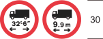 | 1. The numerals may be varied 2. The two lorry symbols may be reversed |
| 34 | Vehicles exceeding width indicated prohibited (Metric and imperial units) |  | The numerals may be varied |
| 35 | Vehicles exceeding height indicated prohibited (Metric and imperial units) |  | The numerals may be varied |
| 36 | Route for use by buses, pedal cycles and taxis only (Alternative types) |  | The cycle symbol, the word “taxi” or both may be omitted |
| 37 | Route for use by buses, pedal cycles and solo motor cycles only (Alternative types) |  | |
| 38 | Route for use by buses, pedal cycles, solo motor cycles and taxis only (Alternative types) |  | |
| 39 | Route for use by tramcars only |  | |
| 40 | Route for use by tramcars and buses only (Alternative types) |  | |
| 41 | Route for use by tramcars, buses and pedal cycles only (Alternative types) |  | |
| 42 | Route for use by tramcars, buses, pedal cycles and taxis only (Alternative types) |  | |
| 43 | Route for use by tramcars, buses, pedal cycles, solo motor cycles and taxis only (Alternative types) |  | The word “taxi” may be omitted |
| 44 | Optional symbol representing a supplementary plate for use with symbols at items 1 to 43, indicating the distance to a hazard or prohibition |  | 1. The distance may be varied 2. The black border must be omitted when the symbol is placed on a blue, dark green or brown background part of the sign. |
| 45 | Optional symbol representing a supplementary plate for use with circular symbols from this table (except items 23, 37 and 38), indicating conditions relating to a prohibition |  | 1. The legend may be varied in accordance with paragraphs 8 and 15, or a combination of both, in Part 3 of Schedule 3 2. The legend may be varied to “Except trams” when the symbol is used in combination with the symbol shown by the diagram at item 22 3. The legend may be varied to “No explosives” or “No inflammables or explosives” when the symbol is used in combination with the symbol at item 27 4. The legend may be varied to “and authorised vehicles” when the symbol is used in combination with a symbol at items 39 to 46 5. The black border may be omitted when the symbol is placed on a blue, dark green or brown background part of the sign |
PART 21Provisions applying to Part 22
1. Information of a description in column 2 of an item in the sign table in Part 22 must be conveyed by the sign shown by either diagram A or diagram B in column 3, including any appropriate symbol or legend that is required or permitted by virtue of column 4.
2. A sign for conveying the description of information must be of—
(a)the colour and type shown in the diagram in column 3 of that table in respect of that item; and
(b)the size appropriate to accommodate a legend of a size specified in column 4 of the table in respect of the item.
PART 22Sign background for signs indicating services
Sign table — Schedule 12, Part 22
(1) Item | (2) Description | (3) Sign background | (4) Legend height, requirements and variants |
|---|---|---|---|
| 1 | Sign indicating a motorway service area or motorway rest area where parking, toilets and, in the case of a service area, fuel and refreshments are available 24 hours a day throughout the year (Type A and B) |  | 1. The x-height of the legend must be not less than 75 mm, nor more than 400 mm; 2. The legend “Services” must be included on the sign or it may be varied to “Rest area”, or a geographical name and “services” or “rest area”; 3. Diagram A may incorporate an arrow as shown at item 1 of the sign table in Part 24 and where indicating the exit from a motorway the sign may also incorporate the number of the route to which the exit leads; 4. Diagram A may incorporate a distance in accordance with paragraph 7 of Part 3 of Schedule 18; 5. Diagram B may be reversed to point right; 6. Where diagram A does not incorporate an arrow, it may incorporate the symbols shown in column 3 of the sign table in Part 24 at items 2 to 11 except that no more than six symbols, excluding that at item 9, may be shown; 7. Diagram A may incorporate either a panel shown at item 14 or 15 of the sign table in Part 24, except that the panel shown at item 14 must not be incorporated where the sign incorporates a symbol shown at item 11 of that table |
| 2 | Sign indicating services on a primary or non-primary route, other than a motorway service area, where fuel, parking, refreshments and toilets are available at least between 8 am and 8 pm on every day except Christmas Day, Boxing Day and New Year’s Day (Type A and B) |  | 1. The x-height of the legend must be not less than 75 mm, nor more than 300 mm; 2. The legend “Services” must be included on the sign or it may be varied to a geographical name and “services”; 3. Diagram A may incorporate the arrows and symbols shown in Part 24 of this Schedule as appropriate except that no more than six symbols, excluding that at item 12 of the sign table in that Part, may be shown; 4. Diagram A may incorporate a distance in accordance with paragraph 7 of Part 3 of Schedule 18; 5. Diagram A may incorporate either a panel provided for at item 16 or 17 of the sign table in Part 24 of this Schedule; 6. Diagram B may be reversed to point right |
| 3 | Sign indicating either a motorway truckstop where parking, refreshments, toilets and fuel are available 24 hours a day throughout the year, or a non-motorway truckstop where parking, refreshments and toilets are available, and fuel may be available, at least between 8 am and 8 pm on every day except Christmas Day, Boxing Day and New Year’s Day (Type A and B) |  | 1. The x-height of the legend must be not less than 75 mm, nor more than 400 mm; 2. The legend “Truckstop” must be included on the sign or it may be varied to a geographical name and “truckstop”; 3. Diagram A may incorporate an arrow shown at item 1 of the sign table in Part 24; 4. Where diagram A indicates a motorway truckstop and does not incorporate an arrow, the sign may incorporate the symbols shown at items 2 to 8 and 11 in the sign table in Part 24 except that no more than six of these symbols may be shown; 5. Where diagram A indicates a non-motorway truckstop it may incorporate the symbols shown at items 2 to 8 in column 3 of the sign table in Part 24 except that no more than six of these symbols may be shown; 6. Diagram A, when indicating a motorway truckstop, may incorporate a panel provided for at item 14 or 15 of the sign table in Part 24, except that the panel at item 14 must not be incorporated where the sign incorporates a symbol provided for at item 11 in that table; 7. Diagram A when indicating a non-motorway truckstop, may incorporate a panel provided for at item 16 or 17 of the sign table in Part 24; 8. Diagram A may incorporate a distance in accordance with paragraph 7 of Part 3 of Schedule 18; 9. Diagram B may be reversed to point right |
PART 23Provisions applying to Part 24
1. Information of a description in column 2 of an item in the sign table in Part 24 must be conveyed on a sign provided for in the sign table in Part 22 by an arrow, symbol or panel (as the case may be) shown in the diagram in column 3 of the sign table in Part 24, or that diagram as varied or supplemented in accordance with column 5.
2. An arrow, symbol or panel may only be placed on an appropriate diagram A sign (this is subject to paragraph 4).
3. For the purposes of this Part, an appropriate diagram A sign is a sign shown in diagram A in column 2 of the sign table in Part 22 for an item of that table, the number of which is specified in column 4 of the sign table in Part 24.
4. The truck symbol provided for at item 13 of the sign table in Part 24 may be placed on a sign shown in diagram B at item 3 of the sign table in Part 22.
5. The symbol or panel shown by the diagram in column 3 of the sign table in Part 24 at item 9, 11, 14 or 15 may only be incorporated in an appropriate diagram A sign which is placed on the main carriageway of a motorway.
6. The arrows, symbols or panels shown on a sign for conveying a description of information in column 2 of an item in the sign table in Part 24 must be of the size, colour and type shown in the diagram in column 3.
7. The sizes in the diagram are stroke widths.
PART 24Arrows, symbols and panels that may be placed on a services sign
Sign table — Schedule 12, Part 24
(1) Item | (2) Description | (3) Diagram | (4) Part 22 diagram A item number | (5) Variants and supplementary information |
|---|---|---|---|---|
| 1 | Directional arrow (Alternative types) |  | 1, 2, 3 | 1. The direction in which the arrow shown by diagram A points may be varied; 2. The arrow must be white when placed on a blue or black background part of the sign |
| 2 | Symbol: Restaurant |  | 1, 2, 3 | The symbol must be white when placed on a blue or black background part of the sign |
| 3 | Symbol: Light refreshment facilities |  | 1, 2, 3 | The symbol must be white when placed on a blue or black background part of the sign |
| 4 | Symbol: Picnic area with a minimum of ten tables, each with seating for six persons |  | 1, 2, 3 | The symbol must be white when placed on a blue or black background part of the sign |
| 5 | Symbol: Overnight accommodation |  | 1, 2, 3 | 1. The symbol must be reversed when incorporated on a sign with a right pointing arrow; 2. The symbol must be white when placed on a blue or black background part of the sign |
| 6 | Symbol: Tourist Information Centre or Point |  | 1, 2, 3 | 1. The symbol must be white when placed on a blue or black background part of the sign; 2. The background colour of the symbol must be the same as the background of the sign on which it is incorporated |
| 7 | Symbol: LPG fuel |  | 1, 2, 3 | 1. The symbol must be white when placed on a blue or black background part of the sign; 2. The background colour of the symbol must be the same as the background of the sign on which it is incorporated |
| 8 | Symbol: Fuel |  | 1, 2, 3 | 1. The symbol must not be used in combination with the unleaded petrol symbol shown in item 9; 2. The symbol must be white when placed on a blue or black background part of the sign |
| 9 | Symbol: Unleaded petrol |  | 1 | 1. The word “Petrol” must always be used in combination with and placed to the left of the symbol; 2. The price of unleaded petrol in pence must be shown to the right of the symbol, followed by the letter “p”; 3. The figures indicating the price of unleaded petrol may be displayed, in any appropriate style, as variable legends in white characters on the blue background of the sign or displayed as variable legends in white or yellow characters on a black background; 4. The symbol must not be used in combination with the fuel symbol shown in item 8 |
| 10 | Symbol: Facilities for recharging electric vehicles |  | 1, 2 | The black patch must be omitted when the symbol is placed on a blue background, in which case the size of the car and plug symbol must be increased proportionally to a height of 14 stroke widths |
| 11 | Symbol: Corporate identifier (more than one identifier may be shown on a sign) |  | 1, 3 | 1. The corporate identifier must be a logo of appropriate colours and design, contained within the white border of the square symbol; 2. The background of the symbol within the border may be of any colour appropriate to the logo; 3. The background colour on which the symbol is placed must be black on the sign provided for at item 3 of the sign table in Part 22 |
| 12 | Symbol: Facilities provided only for vehicles other than heavy goods vehicles |  | 2 | The symbol must be reversed when incorporated on a sign with a right pointing arrow |
| 13 | Symbol: Facilities provided only for heavy goods vehicles (truckstop) |  | 3 | 1. The symbol may be reversed; 2. “Lorries only” may be added below the lorry symbol |
| 14 | Panel: Name of operator (at the top of the sign) |  | 1, 3 | 1. The name of the operator may be varied, may be in any style of lettering and may include a logo; 2. The legend, logo, background and border may be in any contrasting colours; 3. The border may be omitted |
| 15 | Panel: Name of operator (at the top of the sign) |  | 1, 3 | 1. The name of the operator may be varied, may be in any style of lettering and may include a logo; 2. The legend, logo and background may be in any contrasting colours; 3. A white border may be added to the inside edge of the panel, to ensure adequate contrast between the panel and the background of the sign |
| 16 | Panel: Services not open for 24 hours (within the sign) |  | 2, 3 | The panel must have white letters on a black background with a white border when incorporated in diagram A at item 3 of the sign table in Part 22 |
| 17 | Panel: Fuel only available 24 hours a day (at the bottom of the sign) |  | 2, 3 | The panel must have white letters on a black background with a white border when incorporated in diagram A at item 3 of the sign table in Part 22 |
PART 25Provisions applying to Part 26
1. A description of information in column 2 at an item of the sign table in Part 26 must be conveyed by a sign which is of the colour and type, and complies with the requirements as to size, shown in the diagram in column 3, or that diagram as varied in accordance with column 4.
2.—(1) This paragraph applies to a legend on a sign provided for at item 6 or 7 of the sign table in Part 26 where the legend is the name of a place that is a city, town, or village.
(2) On a sign placed in Scotland, the name of the place may be written in Scottish Gaelic, in addition to English, provided the Scottish Gaelic version is shown above the English.
(3) Where the name is the same in English and Scottish Gaelic, it may be written only once on the sign in a manner which complies with the requirements of these Regulations applicable to a name written in—
(a)English; or
(b)Scottish Gaelic.
PART 26Miscellaneous signs indicating services and local facilities
Sign table — Schedule 12, Part 26
(1) Item | (2) Description | (3) Diagram | (4) Permitted variants |
|---|---|---|---|
| 1 | Diagram 2917.1 Availability of motorway service areas ahead, including services for lorries only (truckstop), with distances in miles and geographical names |  | 1. The geographical names of the service areas and the words “NO SERVICES” may be varied or omitted as appropriate; 2. The lorry symbol and “only” may be omitted; 3. The numerals expressing distance may be varied with the only permitted distance that is less than a mile being “⅔ m” with distances greater than 1 mile being expressed to the nearest mile; 4. Motorway numbers, with or without compass points, may be varied or omitted as appropriate; 5. The number of service areas indicated may be varied; |
| 2 | Diagram 2917 Availability of motorway service areas ahead with distances in miles and names of operators |  | 1. The names of the service area operators and the words “NO SERVICES” may be varied or omitted as appropriate; 2. The numerals expressing distance may be varied with the only permitted distance that is less than a mile being “⅔ m” with distances greater than 1 mile being expressed to the nearest mile; 3. Motorway numbers, with or without compass points, may be varied or omitted as appropriate 4. The number of service areas indicated may be varied; |
| 3 | Diagram 2918 Distance to next motorway service area |  | The numeral may be varied with the distance expressed in miles to the nearest mile |
| 4 | Diagram 2918.1 Sign placed on or near a motorway indicating that services are not available |  | |
| 5 | Diagram 2330 Sign placed on or near a primary or non‑primary route indicating that services are not available on motorway ahead | 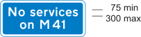 | 1. The motorway number may be varied and include a compass point as appropriate; 2. The motorway number may be varied to “motorway” |
| 6 | Diagram 2308.1 Junction ahead on a primary or non-primary route leading to a small town or village not on a main through route, which provides parking, public toilets, refreshments and fuel during normal shop opening hours at least (Alternative types) |  | 1. The place name may be varied or omitted; 2. “local” must be varied to “Local” when the place name is omitted; 3. “local facilities” may be omitted; 4. A distance in accordance with Part 3 of Schedule 18 may be added except that the distance must not be expressed in yards; 5. The direction in which the arrow points may be varied and where the arrow points ahead and there is a single line of legend, the arrow shown by diagram B at item 1 of the table in Part 24 of this Schedule must be used; 6. Symbols other than the “WC”, petrol pump and cup (denoting light refreshments) may be omitted as appropriate; the wheelchair symbol (denoting facilities for disabled people), when shown, must always be placed to the right of the “WC” symbol; the “i”, spoon and fork, and bed symbols represent tourist information, restaurant and overnight accommodation respectively and symbols may be shown on a single line |
| 7 | Diagram 2309.1 Direction and distance in miles to a small town or village offering facilities indicated on the sign shown in item 5 of this table |  | 1. The place name may be varied or omitted; 2. “local” must be varied to “Local” when the place name is omitted; 3. The direction in which the sign points may be reversed; 4. The distance may be varied to another in accordance with Part 3 of Schedule 18 except that the distance must not be expressed in yards |
PART 27Provisions applying to Part 28
1. Information or a warning of a description in column 2 of an item in the sign table in Part 28 must be conveyed by a sign which is of the colour and type, and complies with the requirements as to size, shown in the diagram in column 3, or that diagram as varied in accordance with column 4.
2. A sign provided for at item 17 must be internally lit.
3.—(1) This paragraph applies to a legend that is used on a sign provided for at item 2, 3 (other than when placed on a motorway), 7, 8, 9 or 10 of the table in Part 28 where the legend is the name of a place that is a city, town, village or tourist destination.
(2) On a sign placed in Scotland, the name of the place may be written in Scottish Gaelic, in addition to English, provided the Scottish Gaelic version is shown above the English.
(3) Where the name is the same in English and Scottish Gaelic, it may be written only once on the sign in a manner which complies with the requirements of these Regulations applicable to a name written in—
(a)English; or
(b)Scottish Gaelic.
4. Paragraph 2 of the Schedule 12 General Directions, applies to the sign provided for at item 21 of the sign table in Part 28.
5.—(1) The signs mentioned in sub-paragraph (2) need not be illuminated.
(2) The signs are those provided for at items 7, 8, 9, 14, 19, 20 and 21 of the Part 28 sign table.
(3) Sub-paragraph (1) does not apply to a sign provided for at item 8 when placed on a motorway.
PART 28Other directional signs
Sign table — Schedule 12, Part 28
(1) Item | (2) Description | (3) Diagram | (4) Variants |
|---|---|---|---|
| 1 | Diagram 2904.2 Indication of road layout at a junction ¾ mile ahead on a motorway, where the left hand lane leaves the main carriageway and where the same exit can be accessed from the centre lane | 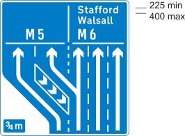 | 1. Destinations may be varied or added and may incorporate the legends shown in column 3 of the sign table in Part 3 at items 1 and 4, and the symbols shown in column 3 of the sign table in Part 11 at items 6, 7, 11, 12, 13 and 21; 2. The number of traffic lanes may be varied and the road marking symbols and arrows varied to represent the actual junction layout; where the two lanes shown for the junction exit lead to different destinations, the horizontal bar must be omitted and the broken line symbol representing the division of the lanes extended upwards; 3. The number of chevron symbols shown may be reduced from three to two, with the boundary line adjusted accordingly; 4. The distance to the junction may be omitted or varied in accordance with paragraph 7 of Part 3 of Schedule 18 |
| 2 | Diagram 2017.1 Indication of road layout at a junction ¾ mile ahead on a primary route, where the left hand lane leaves the main carriageway and where the same exit can be accessed from the centre lane |  | 1. Destinations may be varied or added and may incorporate the legends shown in column 3 of the sign table in Part 3 at items 1 and 4, the panels shown in column 3 of the sign table in Part 9 at items 1 and 3, and the symbols shown in Part 11 (other than items 1 to 5); 2. The number of traffic lanes may be varied and the road marking symbols and arrows varied to represent the actual junction layout. Where the two lanes shown for the junction exit lead to different destinations, the horizontal bar must be omitted and the broken line symbol representing the division of the lanes extended upwards; 3. The number of chevron symbols shown may be reduced from three to two, with the boundary line adjusted accordingly; 4. The distance to the junction may omitted or varied in accordance with paragraph 7 of Part 3 of Schedule 18 |
| 3 | Diagram 2019.1 Indication of appropriate traffic lanes at a junction or at a junction ahead where the right hand lane divides into two, the additional lane on the right leading to a different destination (diagram shows colours applicable to sign on a primary route) |  | 1. Destinations may be varied or added and may incorporate the legends shown in column 3 of the sign table in Part 3 at items 1, 2 and 4, the panels shown in Part 9 and the symbols shown in column 3 of the sign table in Parts 11 (other than items 1 to 5) and 20; 2. The number of traffic lanes and arrows, the widths of individual lanes and the lengths of horizontal bars, may be varied and may indicate an arrangement of shared lanes in a similar manner to column 3 of the sign table in Part 5 at item 5; 3. The route numbers must be white and the background blue when the sign is placed on a motorway exit slip road or the main carriageway of a motorway where it terminates at a junction ahead; 4. The legend, traffic lane symbols, arrows and sign border must be black and the background white when the sign is placed on a non-primary route |
| 4 | Diagram 2912 Junction ahead on a motorway with another motorway |  | 1. Route numbers may be varied in accordance with the entries in column 3 of the sign table in Part 3 at item 4; 2. The junction number in white numerals on the blue background may be added after the word “Junction”; 3. Numerals indicating the distance in miles may be varied with the distance being expressed in miles to the nearest mile |
| 5 | Diagrams 2010.1 and 2010.2 Prohibited movement ahead on a primary route with an indication of a route avoiding that prohibition |  | 1. Numerals in the upper panel of diagram 2010.1 indicating the distance to the prohibited turn may be varied; 2. The route symbols and representation of the road layout may be varied, except that the width of the route symbols must not be varied; 3. The “no right turn” symbol may be reversed to indicate a prohibited left turn or, in diagram 2010.1, varied to the “no U-turn” symbol shown in column 3 of the sign table in Part 20 at item 20; 4. Destinations may be varied or added and may incorporate the legends shown in column 3 of the sign table in Part 3 of this Schedule at items 1 and 4, the panels shown in Part 9 and the symbols shown in Part 11 (other than items 1 to 5); 5. The names of destinations and route numbers may be placed directly on the green background, with the white background omitted, provided destinations are in white lettering and the route numbers are in yellow. |
| 6 | Diagrams 2123 and 2124 Prohibited movement ahead on a non-primary route with an indication of a route avoiding that prohibition |  | 1. Numerals in the upper panel of diagram 2123 indicating the distance to the prohibited turn may be varied; 2. The route symbols and representation of the road layout may be varied as appropriate, except that the width of the route symbols must not be varied; 3. The “no right turn” symbol may be reversed to indicate a prohibited left turn or, in diagram 2123, varied to the “no U-turn” symbol shown in column 3 of the sign table in Part 20 at item 20; 4. Destinations may be varied or added and may incorporate the legends shown in column 3 of the sign table in Part 3 at items 1 and 4, the panels shown in Part 9 and the symbols shown in Part 11 (other than items 1 to 5) |
| 7 | Diagram 2141 Direction for traffic on a minor route to a destination reached along another minor route (Alternative types) |  | 1. Place names may be varied or added in accordance with column 3 of the sign table in Part 3 at item 1 in and may be shown in lower case letters with initial capitals; 2. A distance may be added; 3. The shape of the end of the sign may be varied; 4. A thin black border may be added or omitted as appropriate; 5. The sign may point to the left |
| 8 | Diagram 2215 Junction ahead leading to a place or geographical area containing several tourist destinations or leisure facilities (Alternative types) |  | 1. The place name and the name of the tourist destination or leisure facility may be varied in accordance with column 3 of the sign table in Part 3 at items 1 and 3; 2. The number of tourist destinations or leisure facilities shown on the lower part of the sign may be varied, but must not exceed five and, in the case of a sign placed on a motorway, must not exceed three; 3. The symbols may be varied to those shown in Parts 14 to 18; 4. A distance in relation to each destination shown on the sign may be added; 5. The direction in which the arrow points may be varied |
| 9 | Diagram 2205 Sign on a primary or non-primary route indicating location of a Tourist Information Centre or Point |  | 1. The name of a place or geographical area may be added in the same size of letters as “Tourist information centre”; 2. “centre” may be omitted; 3. The distance may be varied in accordance with Part 3 of Schedule 18; 4. The arrow may be reversed to point horizontally to the right; 5. The distance, the arrow or both may be omitted |
| 10 | Diagram 2307 Sign on a primary or non-primary route indicating distance ahead to a parking place with public toilets that has facilities for disabled persons, Tourist Information Centre or Point, public telephone, picnic area and viewpoint |  | 1. The name of the place may be varied (including to a geographical area) or omitted; 2. The recycling symbol shown in column 3 of the sign table in Part 11 at item 14 may be added; 3. Any of the symbols may be omitted but there must be at least two symbols on the sign including the “P” and either the “i”, picnic area or viewpoint symbol. The wheelchair symbol, when used, must be placed to the right of the “WC” symbol; it must not be included without the “WC” symbol; 4. The distance may be varied in accordance with Part 3 of Schedule 18; 5. An arrow pointing horizontally to the left or to the right may be added; 6. The wheelchair and viewpoint symbols must be reversed when an arrow pointing to the right is added; 7. The distance may be omitted when an arrow is added |
| 11 | Diagram 2301.1 Sign on a primary or non-primary route indicating distance and direction to a caravan site which has at least 20 pitches (where the site is both a caravan and a camping site, the reference to the number of pitches includes both pitches for caravans and for tents) |  | 1. The name of the caravan site may be varied or omitted; 2. The distance may be varied in accordance with Part 3 of Schedule 18; 3. The arrow may be reversed to point horizontally to the right; 4. The distance or the arrow, but not both, may be omitted |
| 12 | Diagram 2301.2 Sign on a primary or non-primary route indicating distance and direction to a camping site which has at least 20 pitches (where the site is both a caravan and a camping site, the reference to the number of pitches includes both pitches for caravans and for tents) |  | 1. The name of the camping site may be varied or omitted; 2. The distance may be varied in accordance with Part 3 of Schedule 18; 3. The arrow may be reversed to point horizontally to the right; 4. The distance or the arrow, but not both, may be omitted |
| 13 | Diagram 2303 Sign on a primary or non-primary route indicating distance and direction to a hostel |  | 1. “Youth Hostel” may be varied to “Tourist hostel” in which case the symbol must be omitted; 2. The distance may be varied in accordance with Part 3 of Schedule 18; 3. The arrow may be reversed to point horizontally to the right; 4. The distance or the arrow, but not both, may be omitted |
| 14 | Diagram 2305 Sign on a primary or non-primary route indicating distance and direction to a picnic area |  | 1. The name of the picnic area may be varied or omitted; 2. The distance may be varied in accordance with Part 3 of Schedule 18; 3. The arrow may be reversed to point horizontally to the right; 4. The distance or the arrow, but not both, may be omitted |
| 15 | Diagram 2703.1 Permanently mounted sign indicating a diversion route (Type A and B) |  | 1. The symbol may be varied to one shown in column 3 of the table in Part 11 at item 13; more than one symbol may be shown; 2. Where a symbol is placed above another, the size and proportions of the chevron in diagram B must be varied as appropriate; 3. The direction in which the arrow points in diagram A may be varied; when pointing to the left the arrow must be placed to the left of the symbol; 4. When the arrow in diagram A is pointing ahead it may be placed either to the left or to the right of the symbol and diagram B, shown in column 3 of the sign table in Part 5 at item 1, must be used where there is one symbol or a single row of symbols; 5. The arrow in diagram A may be varied to the arrow shown in column 3 of the sign table in Part 5 at item 2 ; 6. The sign shown by diagram B may be reversed to point left |
| 16 | Diagrams 2709 and 2710 Permanently mounted sign indicating a route for emergency vehicles to a named emergency services incident point |  | 1. The name of the incident point may be varied or omitted; 2. The direction in which the arrow points in diagram 2709 may be varied; 3. The arrow in diagram 2709 may be omitted and the U-turn arrow, in white, shown in column 3 of the sign table in Part 5 at item 2, placed to the right of the legend; 4. The sign shown by diagram 2710 may be reversed to point right |
| 17 | Diagram 2711.1 Direction and distance to emergency exit for pedestrians from a tunnel (Alternative types) |  | 1. The symbols and arrows may be reversed to indicate an exit to the left; 2. The arrow in diagram B may point vertically upwards with the symbol facing either to the left or to the right; 3. The distance may be varied or omitted; 4. Where emergency exits are more than 880 yards apart, distances must be expressed in miles, denoted by “miles” or “mile” as appropriate, and must be to the nearest ¼ mile with the fractions ¾, ½ and ¼ being used |
| 18 | Diagram 2922 Exit from a motorway for works traffic only |  | |
| 19 | Diagram 2801 and 2802 Sign on a primary or non-primary route indicating a route or direction to a testing station for goods vehicles |  | 1. The word “Goods” may be omitted or varied as appropriate to indicate the type or types of vehicle tested; 2. The testing station symbol may be omitted; 3. A distance may be added; 4. The direction in which the arrow points in diagram 2801 may be varied; when pointing to the right it must be placed on the right hand side of the sign with the symbol, if shown, placed to the left of the legend; 5. When the arrow in diagram 2801 is pointing ahead it may be placed either on the left hand or right hand side of the sign, with the symbol, if shown, placed at the opposite end of the sign; 6. The arrow in diagram 2801 may be omitted and the U-turn arrow shown in column 3 of the sign table in Part 5 at item 2, placed on the right hand side of the sign, with the symbol, if shown, placed to the left of the legend; 7. The sign shown by diagram 2802 may point to the left, with the symbol, if shown, placed to the right of the legend |
| 20 | Diagram 2601.2 Indication of a route for cyclists through a road junction ahead (Alternative types) |  | 1. Destinations may be omitted, varied or added and may incorporate the legends shown in column 3 of the sign table in Part 3 at item 1; 2. A distance may be added; 3. The symbols indicating the road layout and the route for cyclists may be varied as appropriate except the individual symbol widths |
| 21 | Diagram 2610.2 Direction along a public right of way, concessionary path or permissive path indicated by waymarks |  | 1. The direction in which the arrow points may be varied, the shaft may be extended and curved; 2. The colour of the arrow may be varied to indicate the type of route, with the background in any colour; 3. “Public Footpath”, “Footpath”, “Bridleway”, “Byway”, “Restricted Byway”, “Concessionary Path”, “Permissive Path” (or other appropriate description for conveying the direction of a public right of way, concessionary path or permissive path) may be added on, or adjacent to, the arrow; 4. The name of a destination, a route and an identifying symbol of a route, in any combination, may be added on or adjacent to the arrow; 5. A distance may be added; 6. A legend may be in any style, size and contrasting colour |
| 22 | Diagram 818.4 Nature and location of a prohibition, restriction or requirement with indication of alternative route |  | 1. The legend above the “weight limit” symbol, indicating the nature and location of the prohibition, restriction or requirement, may be varied as appropriate; 2. The “weight limit” numeral may be varied; 3. The “weight limit” symbol may be varied to a symbol shown in column 3 of the sign table in Part 20 at items 25, 27, 33, 34 or 35 or omitted; 4. A distance to the location of the prohibition, restriction or requirement may be shown in accordance with Part 3 of Schedule 18; 5. An arrow pointing horizontally to the left or to the right may be added (and where an arrow pointing to the right is added, the lorry symbol is reversed); 6. “ahead” may be added after any distance where an arrow has not been added; 7. The legend below the “weight limit” symbol, indicating an alternative route, may be omitted or varied in accordance with column 3 of the sign table in Part 3 at item 8 and may include the words “Alternative route via” |
| 23 | Diagram 818.5 Location of a low bridge with indication of alternative route |  | 1. The legend “south of Maplebeck” may be varied as appropriate or omitted 2. The numerals giving a height may be varied 3. A distance to the low bridge may be shown in accordance with Part 3 of Schedule 18 4. An arrow pointing horizontally to the left or to the right may be added 5. “ahead” may be added after any distance where an arrow has not been added 6. The legend below the “height limit” symbol, indicating an alternative route, may be omitted or varied and may include the legends shown in column 3 of the sign table in Part 3 at item 8 |
| 24 | Diagram 2502 Sign on a primary or non-primary route indicating distance to a goods vehicles parking place ahead with public toilets and telephones |  | 1. The lorry, “WC” and telephone symbol may be omitted as appropriate 2. The recycling symbol shown in column 3 of the table in Part 11 at item 14 may be added 3. The “i” symbol shown in column 3 of the sign table in Part 11 at item 33 may be added where the parking place includes a general information point not associated with tourist destinations 4. The distance may be varied in accordance with Part 3 of Schedule 18 5. An arrow pointing horizontally to the left or to the right may be added 6. An arrow pointing horizontally to the right may be added provided that the lorry symbol, if shown, is reversed 7. The distance may be omitted when an arrow is added |
PART 29The Schedule 12 General Directions
1. Paragraph 2 applies to a sign provided for—
(a)in this Schedule which has a diagram B background as shown at an item in the sign table in Part 2 or 22.;
(b)at item 7 in Part 26; or
(c)at item 7, 15 (type B), 16 (diagram 2710) or 19 (diagram 2802) of Part 28.
2. The sign may only be placed at a junction.
3. Paragraph 4 applies to a sign—
(a)which has a background provided for at item 9 of the Part 2 sign table (routes for pedestrians); or
(b)provided for at item 21 of the sign table in Part 28 (direction along a public right of way etc.).
4. The back of the sign may be of any colour.
Regulation 3, Direction 3
SCHEDULE 13Signs only for use in temporary situations
PART 1Provisions applying to signs in Part 2
1. A warning of a description in column 2 of an item in the sign table in Part 2 must be conveyed by a triangular sign that is of—
(a)the colour and type provided for in the diagram in column 3; and
(b)the size shown in the diagram above the table.
2. A plate containing a legend provided for in column 4 (“a first associated plate”) must—
(a)be of the colour and type; and
(b)comply with the requirements as to size,
provided for in the diagram above the table.
3. If there is a number in column 5, the equivalent item number in the table in Part 4 is a supplementary associated plate for the triangular sign in question.
4. The number in column 6 indicates that the equivalent numbered Schedule 13 General Direction applies to the triangular sign in question.
PART 2Signs for use in temporary situations

Sign table — Schedule 13, Part 2
(1) Item | (2) Description | (3) Diagram | (4) First associated plate legend | (5) Supplementary associated plate by reference to item number in the Part 4 sign table | (6) Schedule 13 General Directions |
|---|---|---|---|---|---|
| 1 | Diagram 551.1 Migratory toad crossing ahead |  | “For” and a distance | ||
| 2 | Diagram 554A Worded warning sign (Flood) |  | 1. A distance with or without an arrow pointing to the left or to the right; or 2. An arrow pointing to the left or to the right | ||
| 3 | Diagram 554D Worded warning sign (No Smoking) |  | 2. A distance with or without an arrow pointing to the left or to the right; or 2. An arrow pointing to the left or to the right | ||
| 4 | Diagram 554.2 Risk of ice or packed snow ahead |  | 1. “Ice”; 2. “Ice for” and a distance; 3. “Snowdrifts”; or 4. “Snowdrifts for” and a distance | 1 | |
| 5 | Diagram 556 Uneven road ahead |  | “For” and a distance | 1 | |
| 6 | Diagram 557 Slippery road ahead |  | “For” and a distance | ||
| 7 | Diagram 562 Other danger ahead |  | 1. A word or phrase at paragraph 4; 2. A word or phrase at paragraph 4 followed by a distance; or 3. The legend at 1 or 2 with an arrow pointing to the left or to the right; 4. The words and phrases are— (a) Accident; (b) Census; (c) Dust cloud; (d) Fallen tree; (e) Frost damage; (f) Overhead cable repairs; (g) Runners in road; (g) Smoke; (h) Walkers in road | 1, 2 or 3 | 1, 2 |
| 8 | Diagram 950 Cycle race or test ahead (Alternative types) |  | 1. A phrase at paragraph 4; 2. A phrase at paragraph 4 followed by a distance; or 3. The legend at 1 or 2 with an arrow pointing to the left or to the right; 4. The phrases are— (a) Child cycle tests; (b) Child cycle tests; (c) Child cycle training; (d) Cycle event; | 1 | |
| 9 | Diagram 7001 Road works or temporary obstruction of carriageway ahead |  | 1. A distance; 2. “For” and a distance; 3. A word or phrase at paragraph 8 (where “End” indicates the end of all restrictions or prohibitions associated with road works); 4. A word or phrase at paragraph 8 (other than “End”) followed by a distance; 5. An arrow pointing to the left or to the right on its own or with the legend at 1, 3 or 4; 6. “On” and a route number, with or without a direction of travel; or 7. A route number with or without a direction of travel; 8. The words and phrases are— (a) Line painting; (b) At level crossing; (c) Blasting; (d) Ditching; (e) Grass cutting; (f) Gritting; (g) Gully emptying; (h) Hedge cutting; (i) Lighting maintenance; (j) Mobile road works; (k) On hard shoulder; (l) On slip road; (m) Overhead works; (n) Road sweeping; (o) Salting; (p) Sign erection; (q) Sign maintenance; (r) Snow ploughing; (s) Surveying; (t) Tree cutting; (u) Weed spraying; (v) End | 4, 6(1) | |
| 10 | Diagram 7009 Loose chippings on road ahead |  | 1. A distance; 2. “For” and a distance; or 3. An arrow pointing to the left or to the right on its own or with the legend at 1 or 2 | 2 or 3 | 3 |
PART 3Provisions applying to plates in Part 4
1. A warning of a description in column 2 of an item in the sign table in Part 4 must be conveyed by a plate that—
(a)is of the colour and type; and
(b)complies with the requirements as to size,
provided for in the diagram in column 3.
2. In relation to item 3, the warning is conveyed by both of the plates and paragraph 1 applies to each of those plates.
3. The plate provided for at item 2 may have a different numeral to that shown in the diagram.
PART 4Optional supplementary plates used only in combination with signs shown in Part 2
Sign table — Schedule 13, Part 4
(1) Item | (2) Description | (3) Sign diagram |
|---|---|---|
| 1 | Diagram 511 Reduction in speed necessary at a hazard ahead |  |
| 2 | Diagram 513.2 Maximum speed in mph advised at a hazard. |  |
| 3 | Diagram 7009.1 Risk of skidding and maximum speed 20 mph advised on road with loose chippings |  |
PART 5Provisions applying to signs in Part 6
1. A warning, requirement, restriction or prohibition of a description in column 2 of an item in the sign table in Part 6 must be conveyed by a sign that is of the colour and type, and complies with the requirements as to size, provided for in the diagram in column 3, or that diagram as varied in accordance with column 4.
2. In respect of items 9 and 10, each lamp incorporated into the sign must show an intermittent amber light at a rate of flashing of not less than 60 nor more than 90 flashes per minute, and in such a manner that the lights of one horizontal pair are always shown when the lights of the other horizontal pair are not shown.
3. If a number appears in column 5, the equivalent paragraph number in Part 7 applies to the sign in question.
4. The provisions of Part 8 apply to cones (item 4), delineators (item 5) and cylinders (item 6).
5. A number in column 6 indicates that the equivalent numbered Schedule 13 General Direction applies to the sign in question.
6. Where provision is made in column 4 for a different logo to that shown in the diagram to be included, the logo may incorporate any image and lettering in any style and colour.
7. Where provision is made in column 4 for the name of an organisation to be used instead of a logo, that is a reference to the name being used other than as part of a logo and is not to be taken as preventing the name of the organisation from being incorporated into a logo.
PART 6Additional Temporary Signs
Sign table — Schedule 13, Part 6
(1) Item | (2) Description | (3) Sign diagram | (4) Permitted variants | (5) Applicable requirements in Part 7 | (6) Schedule 13 General Directions |
|---|---|---|---|---|---|
| 1 | Diagram 7006.1 Information on telephone number to be used for enquiries about road works |  | 1. The Highways England logo may be varied to another logo used by Highways England or replaced by “Highways England”; 2. The logo may be varied to “Scottish Government”, “Welsh Government” or a logo of the Scottish or Welsh Government; 3. The logo may be varied to the name or logo of that part of the Scottish or Welsh Government that is, by virtue of the organisation of the government, responsible for the maintenance or improvement of the road; 4. The logo may be varied to the name or logo of another traffic authority; 5. The telephone number may be varied | 9 | 4 |
| 2 | Diagram 7007.1 Relevant particulars of major construction or improvement scheme being carried out on road ahead |  | 1. The Highways England logo may be varied to another logo used by Highways England or replaced by “Highways England”; 2. The Department for Transport logo may be varied to another logo used by the Department or replaced by “Department for Transport”; 3. The Department for Transport logo may be varied to the name or logo of another Department of Her Majesty’s Government; 3. Either or both logos may be omitted; 4. The Highways England or Department for Transport logo (or both) may be replaced by one or two of the following (provided that in total no more than two names or logos are shown)— (a) “Welsh Government” or a logo used by the Welsh Government; (b) “Scottish Government” or a logo used by the Scottish Government; (c) the name or logo of that part of the Scottish or Welsh Government that is, by virtue of the organisation of the government, responsible for the maintenance or improvement of the road; (d) the name or logo of another traffic authority; 5. The particulars of the construction or improvement scheme may be varied | 10 | 4 |
| 3 | Diagram 7008 Nature of street works, giving names of undertaker and contractor, emergency telephone number, and apology for in-convenience (Sign for pedestrians) |  | 1. The name of the undertaker (and logo) and contractor, the nature of the works, the completion date and telephone number may be varied; 2. Each line of lettering may have a different x-height which must be smaller than the telephone number; 3. The description of the works, the completion date and the name of the contractor may be omitted; 4. The top and bottom panels may be in any colour and style of lettering; 5. A logo indicating membership of a national street works good practice scheme may be added to the top or bottom panel; 6. The bottom panel may be omitted; 7. The top panel may be omitted provided the undertaker’s name is shown on the red panel | 10 | 4 |
| 4 | Diagram 7101.1 Edge of a route for vehicle traffic through or past a temporary obstruction (Traffic cone) |  | The colour of the base may be varied in accordance with Part 8, paragraph 2 | 12 | 4 |
| 5 | Diagram 7102 Edge of a route for vehicular traffic through or past a temporary obstruction on a motorway or dual carriageway road (Flat traffic delineator) |  | The colour of the base may be varied in accordance with Part 8, paragraph 4 | 2, 12 | 4 |
| 6 | Diagram 7103 Line of division of traffic flows on one carriageway, or to indicate the edge of a route for vehicular traffic through or past a temporary obstruction, or to mark a boundary between two carriageways of a dual carriageway road which may not be crossed except for fire and rescue authority, Scottish Fire and Rescue Service, ambulance or police purposes (Traffic cylinder) |  | |||
| 7 | Diagram 7104 Sharp deviation of route at or near road works or other temporary obstructions |  | The sign may be reversed to show a deviation to the right | 4, 8 | |
| 8 | Diagram 7105 Position of barrier to mark length of road closed to traffic or to guide traffic past an obstruction |  | 4, 8 | ||
| 9 | Diagram 7402 Lanes closed to traffic ahead by vehicles carrying out mobile road works (Alternative types) |  | 1. The number of arrows and symbols indicating the number of lanes and those which are open or closed to traffic may be varied; 2. “500 yds” may be varied to an alternative distance to the nearest 50 yards, to “Ahead” or, on the lower image, to “On slip road” on two lines; 3. The distance plate may be omitted | 9 | 4, 6(3) |
| 10 | Diagram 7403 Other traffic to keep to the right of vehicles carrying out mobile road works (Alternative types) |  | The arrow may point downwards to the left | 1, 9 | 4, 6(3) |
| 11 | Diagram 610 Sign— (a) attached to the front or back of a road maintenance vehicle to indicate the side on which traffic should pass; or (b) placed in relation to an emergency or breakdown vehicle which is temporarily obstructing the road to warn other traffic of the obstruction and to indicate the way past the vehicle |  | 1. Arrow may point downwards to the left; 2. When attached to a vehicle, the diameter of the sign may be reduced to 1200 or 900 mm where it is not practicable to mount the 1500 millimetre diameter sign on the vehicle; 3. When placed in relation to an emergency or breakdown vehicle, the diameter may be reduced to 1200 or 900 mm | 1, 11 | 6(1), 6(2) |
| 12 | Diagram 7404 Nature of work being done by vehicle working on the highway (Sign attached to a road maintenance vehicle) |  | 1. “HIGHWAY” may be varied to “MOTORWAY” or “ROAD”; 2. The legend may be on one line | 9, 10 | 4, 6(3) |
| 13 | Diagram 7202.1 Temporary lane availability (Alternative types) |  | 1. The number of arrows and symbols indicating the number of lanes and those which are open or closed to traffic may be varied; 2. Where the sign has a bottom panel, the legend may be varied to another distance or to “On slip road”, provided the legend appears on no more than three lines | 9 | 4 |
| 14 | Diagram 7243 Temporary road layout with lane restrictions |  | 1. In the top panel the legend may be— (a) varied to “REJOIN MAIN CARRIAGEWAY” or “NARROW LANES”; (b) on one line; 2. The top panel may be omitted; 3. In the middle panel— (a) the arrows and symbols may be varied to indicate the layout of the traffic lanes provided that the shape of an arrow head is not varied; (b) an individual arrow may include more than one arrow head; (c) the numerals on the width limit symbol may be varied; (d) the width limit symbol may be omitted or varied to a symbol shown in column 3 of the sign table in Part 20 of Schedule 12 at items 24, 25, 28, 30, 33, and 35; (e) the size of a symbol referred to in paragraph (d) may be varied from that shown for the symbol in Part 20 of Schedule 12; (f) route numbers may be added with the x-height being 100, 125 or 150 mm; (g) the route numbers referred to in paragraph (f) may be followed by “only” at the same x-height; (h) a motorway junction number in white characters on a black patch may be added in a manner similar to the patch shown in the diagram at item 15, the x-height being 80, 100 or 120 mm; (i) a horizontal bar may be added in the manner shown in the diagram at item 15 where two or more lanes are associated with the same route number; (j) a white downward pointing arrow, as shown in the upper diagram at item 13, may be added to indicate a contraflow traffic lane 4. In the bottom panel— (a) the numerals indicating the maximum speed advised may be varied; (b) the legend may be varied to a distance with an x-height of 100 mm, 125 mm or 150 mm; (c) the distance referred to in paragraph (b) may be preceded by “For”; 5. The bottom panel may be omitted | 9 | 4, 5 |
| 15 | Diagram 7244 Temporary road layout, with an indication of destinations and route numbers, where the sign is placed on a motorway |  | 1. A panel with the legend “USE HARD SHOULDER”, “REJOIN MAIN CARRIAGEWAY”, “NARROW LANES”, “EVENT TRAFFIC” or other appropriate legend, may be added above the top panel in a manner similar to the top panel shown in the diagram at item 14 with an x-height of not less than 100 mm, nor more than 150 mm; 2. In the top panel— (a) the arrows may be varied to indicate the layout of the traffic lanes provided the shape of an arrow head is not varied; (b) a white downward pointing arrow, as shown in the upper diagram at item 13, may be added to indicate a contraflow traffic lane; (c) the symbol indicating a closed lane, as shown in the diagrams at item 13, may be added; (d) where the sign is placed other than on a motorway, any route number must have characters of the form shown in Part 2 of Schedule 17 with an x- height of not less than 100 mm, nor more than 150 mm; (e) a symbol shown in a diagram in Part 11 or 20 of Schedule 12 may be added and the size of the symbol may be varied from that shown; (f) a destination or route number may be varied or omitted, and additional destinations and route numbers added; (g) the junction number may be varied or omitted; 3. In the bottom panel the distance may be varied; 4. The bottom panel may be omitted | 9 | 4, 5 |
| 16 | Diagram 7245 Temporary road layout |  | 1. In the top panel the legend may be- (a) varied to “USE HARD SHOULDER” or “NARROW LANES”; (b) on one line; 2. The top panel may be omitted; 3. In the middle panel— (a) the arrows and symbols may be varied to indicate the layout of the traffic lanes provided the shape of an arrow head is not be varied; (b) an individual arrow may include more than one arrow head; (c) black symbols representing the division of traffic lanes may be added in a manner similar to that shown at item 14 of the sign table in Part 2 of Schedule 11 or at item 1 of the sign table in Part 28 of Schedule 12; (d) a white downward pointing arrow as shown in the upper diagram at item 13 may be added to indicate a contraflow traffic lane; (e) destinations and route numbers may be added with an x-height of 100, 125, 150 or 175 mm; (f) a junction number panel may be added in a manner similar to that shown in the diagram at item 15, the x-height being 80, 100, 120 or 140 mm; (g) symbols provided for in Parts 11, 12, 14, 15, 17 and 18 of Schedule 12 may be added; 4. In the bottom panel— (a) the numerals indicating the maximum speed advised may be varied; (b) the legend may be varied to a distance with an x-height of 100, 125, 150 or 175 mm; (c) the distance may be preceded by “For”; 5. The bottom panel may be omitted | 9 | 4, 5 |
| 17 | Diagram 633 Vehicular traffic must not proceed beyond the sign where displayed by a constable in uniform or by a traffic warden |  | A red or transparent protective strip, with a visible width not exceeding 6 mm, may be applied to the perimeter of the sign | 10 | |
| 18 | Diagram 633.1 Vehicular traffic must not proceed beyond the sign |  | A red or transparent protective strip, with a visible width not exceeding 6 mm, may be applied to the perimeter of the sign | 1, 9 | 9 |
| 19 | Diagram 636 Temporary prohibition of waiting except for loading and unloading |  | 1. The name of the police force or traffic authority, or the word “Police” or “POLICE” may be added above or below the roundel; 2. An arrow pointing to the left or to the right may be added | 10 | 5, 10 |
| 20 | Diagram 636.1 Temporary prohibition of loading and unloading |  | The legend may be on one line | 10 | 5 |
| 21 | Diagram 636.2 Temporary prohibition on stopping during the periods indicated |  | 1. The name of the police force may be varied to the appropriate force, “POLICE” or “Police”, the name of a traffic authority, or omitted; 2. “No stopping” may be on one line; 3. Time periods shown may be varied or omitted | 10 | 5, 10 |
| 22 | Diagram 640.1 Waiting, loading and unloading prohibited at a parking place where parking is temporarily suspended |  | 1. “during meter control” may be added; 2. “No loading” may be omitted; 3. The sign may have more than one side and may be placed on a parking meter or ticket machine cover; 4. The symbol and legend may be repeated | 10 | 5 |
| 23 | Diagram 829.1 Potential danger temporarily ahead and consequent need to proceed with caution |  | ` | 7, 10 | |
| 24 | Diagram 829.2 Accident ahead and consequent need to proceed with caution |  | 7, 10 | ||
| 25 | Diagram 829.3 Traffic should use the hard shoulder in an emergency |  | 7, 10 | ||
| 26 | Diagram 829.4 End of temporary permission for traffic to use the hard shoulder |  | 7, 10 | ||
| 27 | Diagram 832.7 Goods vehicles or public service vehicles (PSV) should get into the left hand lane of a carriageway on the approach to a goods vehicle or PSV check point ahead |  | 1. “GET IN LANE” may be varied to “STAY IN LANE”; 2. The number and position of lanes may be varied; 3. The bus symbol shown in the sign table at item 4 of Part 3 of Schedule 5, with a red diagonal bar through it, may be added below, or substituted for, the lorry symbol (ignoring the requirements as to size at item 4); 4. The legend “Any vehicle” may be varied to “Other vehicles” with the lorry and bus symbols shown without the red bar; 5. “Goods vehicle” may be varied to “Goods vehicle and PSV” or “PSV”; 6. The distance may be varied to “1 m”, “2/3 m” or “1/3 m” | ||
| 28 | Diagrams 2701 and 2701.1 Direction and junction ahead to a new housing development |  | 1. The sign shown by diagram 2701 may point to the left with the symbol placed to the right of the legend; 2. The direction in which the arrow points in diagram 2701.1 may be varied; 3. When the arrow in diagram 2701.1 points to the left it must be placed on the left hand side of the sign with the symbol placed to the right of the legend; 4. When the arrow in diagram 2701.1 points ahead it may be placed on the left or right hand side of the sign with the symbol placed at the opposite end of the sign; 5. The arrow in diagram 2701.1 may be omitted and the U-turn arrow shown in column 3 of the sign table in Part 5 of Schedule 12 at item 2, placed to the right of the legend; 6. The name of the housing development may be varied or omitted; 7. A distance to the destination may be shown (and the sign treated for the purposes of Part 3 of Schedule 18 as if it were in Schedule 12); 8. The lorry symbol shown at item 5 of the sign table in Part 1 of Schedule 5 may be added (ignoring the requirements as to size at item 5) and reversed where appropriate | 10 | 11 |
| 29 | Temporary obstruction in road caused by stationary vehicle (road vehicle sign) |  | 3, 12 | 6(5) | |
| 30 | Warning of a temporary hazard (traffic pyramid (type 1)) |  | 4, 12 | ||
| 31 | Warning of a temporary hazard (traffic pyramid (type 2)) |  | 5, 12 | ||
| 32 | Warning of a temporary hazard (traffic triangle (type 1)) |  | 6, 12 | ||
| 33 | Warning of a temporary hazard (traffic triangle (type 2)) |  | 7, 12 | ||
| 34 | Diagram 7025 Vehicles to be escorted in through road works ahead |  | 4 | ||
| 35 | Diagram 7026 Explanation of reason for escorting vehicles in convoys through road works |  | 4 | ||
| 36 | Diagram 7029 Vehicular traffic must not overtake the vehicle used to escort other vehicles through road works |  | 1. “NO OVERTAKING” may be omitted; 2. “CONVOY VEHICLE” may be on one line | 1 (except if varied in accordance with entry 1 in column 4) | 4, 6(4) |
| 37 | Diagram 7014 Permanent change in road layout ahead |  | 1. “NEW ROUNDABOUT” may be varied to— (a) “CHANGED PRIORITIES”; (b) “GAP CLOSED”; (c) “NEW ONE WAY SYSTEM”; (d) “NEW ROAD LAYOUT”; (e) “NEW TRAFFIC ISLANDS”; (f) “NEW TRAFFIC SIGNALS”; (g) “NEW ZEBRA CROSSING”; (h) “SIGNAL PRIORITIES CHANGED”; or (i) “SIGNAL TIMING CHANGED”; 2. A distance in yards to the nearest 10 yards may be substituted for, or added before, the word “AHEAD”, on a separate line where necessary, and must be expressed as “yards” or “yds” | 8 | 12 |
| 38 | Diagram 7032 Commencement point of a newly imposed 30 mph speed limit which is contiguous to an existing 30 mph speed limit |  | 8 | 13 | |
| 39 | Diagram 7014.1 Temporary or permanent reduction in bridge headroom ahead |  | The numerals may be varied. | 8 | 14 |
| 40 | Diagram 7291 Information on breakdown recovery services during road works |  | “Await rescue” may be varied to “End”. | 9 | 4 |
| 41 | Diagram 7294 Temporary maximum speed in mph advised |  | The numerals may be varied to the appropriate advised maximum speed | 9 | 4 |
| 42 | Diagram 7003.1 Starting date and duration of road works |  | 1. The Highways England logo may be varied to another logo used by Highways England or replaced by “Highways England”; 2. The Highways England logo may be varied to the name or logo of another traffic authority; 3. The date and duration of the work may be varied; 4. “until” and a date may be substituted for “ for 3 weeks”; 5. The top or bottom panel, or both, may be omitted; 6. The triangular road works symbol may be omitted | 4 | |
| 43 | Diagram 7005 Information for drivers in respect of road works |  | 1. The date may be varied; 2. “until” and the date may be omitted; 3. “Delays possible until” and the date may be varied to a short description of the work in progress or explanation of why work is suspended; 4. The distance may be varied, may be preceded by “For” and may be on two lines; 5. The triangular road works symbol and distance plate may be omitted | 4 | |
| 44 | Diagram 7006 End of road works and any associated temporary statutory restrictions |  | 1. The Highways England logo may be varied to another logo used by Highways England or replaced by “Highways England”; 2. The Highways England logo may be varied to the name or logo of another traffic authority; 3. The Highways England panel and the horizontal line below “delay” may be omitted | 4 | |
| 45 | Diagram 2708 Junction ahead leading to route for emergency vehicles to a temporary incident control point |  | 1. “EMERGENCY VEHICLES” may be varied to “INCIDENT CONTROL”; 2. The direction in which the arrow or arrows point may be varied | ||
| 46 | Diagram 830.1 Signs indicating that a traffic survey is being undertaken |  | 1. “CENSUS” may be varied to “CYCLISTS”, “WEIGHT CHECK” or “VEHICLE CHECK; 2. The entire legend may be varied to “STOP AT CENSUS POINT”, ”SLOW CENSUS POINT” or “CENSUS POINT”; 3. For the purposes of entry 2, “CENSUS POINT” may be varied to “WEIGHT CHECK” or “CHECK POINT” | 15 | |
| 47 | Diagram 830.2 Goods vehicles may be directed to stop ahead by a constable in uniform for the purposes of sections 67,68, or 78 of the Road Traffic Act 1988(82) |  | |||
| 48 | Diagram 830.3 Vehicles should stay in lane for the purposes of a traffic survey, or a weight or vehicle check ahead |  | “STAY” may be varied to “GET” | 15 | |
| 49 | Diagram 831.2 Checks being made in relation to vehicle excise licences (or emissions) ahead |  | “EXCISE LICENCE” may be varied to “EMISSIONS” | ||
| 50 | Diagram 832.1B Check point ahead |  | 1. “DVSA” may be varied to “GOODS VEHICLE” or the name of a successor organisation to the Driver and Vehicle Standards Agency (in respect of its function of carrying out examinations in relation to goods vehicles or public service vehicles at check points) or an acronym for that successor organisation; 2. “CHECK POINT AHEAD” may be varied to “VEHICLE CONDITION INSPECTION” | ||
| 51 | Diagram 832.4 Instructions in relation to goods vehicles for a check point ahead |  | 1. The legend may be varied to “Enter Check Point”, “Keep to left lane” or “Leave m’way if directed”; 2. The bus symbol shown at item 4 of the sign table in Part 3 of Schedule 5 may be added below or substituted for the symbol (ignoring the requirements as to size at item 4) | ||
| 52 | Diagram 7020 Variable message sign ahead not in use or being tested |  | 1. “SIGN” may be varied to “SIGNAL”; 2. “NOT IN USE” may be varied to “UNDER TEST”; 3. The legend may be on three lines |
PART 7Provisions applying to signs in Part 6
1. Section 36 of the 1988 Act applies to the sign.
2. The sign must be of the size, colour and type shown in the two parts of the diagram in column 3.
3.—(1) The sign must be a flexible sheet on which a triangle appears and the total area of the sheet, including the red triangle, must be not less than 0.8 square metres.
(2) The triangle must be equilateral.
(3) The area marked A must be reflectorised.
(4) Where the area marked B is coloured white (as shown in the diagram) it must be reflectorised.
(5) The area marked B may be coloured yellow;
(6) Any part of the sign coloured yellow must be fluorescent and may be reflectorised.
4.—(1) The pyramid must consist of three visible sides, each of which is as specified in the diagram.
(2) It must be made of rubber or flexible plastic material.
(3) It must be constructed so that it can stand upright firmly on the surface of a road.
(4) The surface coloured red (marked A and C) may be reflectorised.
(5) The surface coloured white (marked B) must be reflectorised.
(6) Up to 50% of the surface marked C may be obscured by constructional components.
(7) The pyramid must not be illuminated through internal or external illumination.
(8) The base may be of any colour, or omitted.
5.—(1) The pyramid must consist of three visible sides, each of which is as specified in the diagram.
(2) It must be made of rubber or flexible plastic material.
(3) It must be constructed so that it can stand upright firmly on the surface of a road.
(4) The surface coloured red (marked A) may be reflectorised.
(5) The surface coloured white (marked B) must be reflectorised.
(6) Each outer edge of the triangular face must be the same length.
(7) The pyramid must not be illuminated through internal or external illumination.
6.—(1) The triangle must be legibly and permanently marked with the specification number of the British Standard for an Advance Warning Triangle to indicate a temporary obstruction, namely BS AU47: 1965(83) or the specification number of a corresponding EEA standard.
(2) The surface coloured red and marked A must be reflectorised.
(3) Not more than 15 square centimetre of the surface marked A may be obscured by constructional components.
(4) The surface coloured red and marked B must be fluorescent.
(5) The surface marked C must be either—
(a)entirely reflectorised; or
(b)a combination of reflectorised and fluorescent.
(6) Not more than 10 square centimetre of the surface marked A may be obscured by constructional components.
(7) Corners of a triangle must be radiused.
(8) All sides of a triangle must be of the same length.
(9) The reflectorised areas of the surface may be internally illuminated provided that such illumination is steady, presents a uniform appearance throughout that area and does not impair the retroreflecting properties of that area of the surface.
(10) The triangle must not be illuminated through external illumination.
7.—(1) The triangle must be legibly and permanently marked with the marking designated as an approval mark by regulation 4 of the Motor Vehicles (Designation of Approval Marks) Regulations 1979(84) and shown in item 27 of Schedule 2 to those Regulations.
(2) The surface coloured red and marked A must be reflectorised;
(3) Not more than 15 square centimetre of the surface marked A may be obscured by constructional components;
(4) The surface coloured red and marked B must be fluorescent;
(5) The surface marked C must be either—
(a)entirely reflectorised; or
(b)a combination of reflectorised and fluorescent;
(6) Not more than 10 square centimetre of the surface marked A may be obscured by constructional components;
(7) In the case of the triangle provided for at item 33—
(a)the surface coloured red and marked A must be reflectorised;
(b)the surface coloured red and marked B must be fluorescent and have an area of not less than 315 square centimetres;
(c)the edging coloured red and marked C may be omitted.
(8) Corners of a triangle must be radiused.
(9) All sides of a triangle must be of the same length.
(10) The reflectorised areas of the surface may be internally illuminated provided that such illumination is steady, presents a uniform appearance throughout that area and does not impair the retroreflecting properties of that area of the surface.
(11) The triangle must not be illuminated through external illumination.
8. The sign must have, on its reverse, a date by which the person placing the sign reasonably believes the sign will have been removed.
9. The yellow may be fluorescent.
10. The sign need not be illuminated.
11. A person who is in charge of, or accompanies, an emergency or a breakdown vehicle which is temporarily obstructing a road is authorised to place the sign for the purpose of warning vehicular traffic of the obstruction created by the vehicle and to indicate the way past the vehicle
12. A person that, but for this paragraph, is not authorised to place the sign is authorised to do so for the purpose of warning traffic of a temporary obstruction in the road, other than one caused by the carrying out of works.
PART 8Requirements applying to cones, cylinders and delineators
1. A cone is to consist of a conically shaped device—
(a)the base of which is—
(i)of any single colour; and
(ii)a polygon having not more than eight sides, which would be contained wholly within a circle with a diameter of three quarters of the height of the cone; and
(b)which conforms to the provisions of British Standard BS EN 13422:2004+A1:2009(85) set out in paragraph 8.
2. A cylinder is to consist of a cylindrically shaped device which conforms to the provisions of British Standard BS EN 13422:2004+A1:2009 set out in paragraph 8.
3. A delineator is to consist of a flat device—
(a)of which the side intended to be exposed to traffic is coloured as shown in the diagram at item 4 of the table in Part 6 and the reverse side is either so coloured or coloured only grey or only red;
(b)which conforms to the provisions of British Standard BS 8442:2015(86); and
(c)of which the base is of any single colour, except that a reflectorised white line 100 mm wide at an angle of not more than 60 degrees to the road surface may be marked on one side of the base at right angles to the face of the delineator.
4. The part of a cone, cylinder or delineator coloured white must, subject to paragraph 7, be illuminated with white retroreflecting material and the part coloured red (except, in the case of a delineator, on the reverse side when that side is coloured only red) may be illuminated with red retroreflecting material.
5. Information about the ownership of a cone, cylinder or delineator may—
(a)in the case of a cone, be moulded—
(i)into the base in characters not more than 80 mm high in the same colour as the base;
(ii)into the conical body in characters not more than 40 mm high in the same colour as that body; or
(iii)as mentioned in both paragraphs (i) and (ii);
(b)in the case of a cylinder, be moulded into the lower of the two red parts of the cylinder in red characters not more than 40 mm high; and
(c)in the case of a delineator, be moulded into the base in characters not more than 80 mm high and in the same colour as the base.
6. Information about the manufacture of a cone, cylinder or delineator required in order to comply with British Standard BS EN 13422:2004+A1:2009 or British Standard BS 8442:2015 (or, in either case, a corresponding EEA standard) and occupying an area not exceeding 30 square centimetres, may be indicated on the part coloured white in characters not exceeding 5 mm in height, leaving at least 90% of the remaining area of white colour illuminated with white retroreflecting material.
7. There may be mounted on top of a cone a rotating device that—
(a)is red and not reflectorised; and
(b)displays a sign provided for at item 2 of the sign table in Part 6 of Schedule 2 which must be coloured amber, intermittently whilst rotating and constantly whilst static.
8. In relation to each aspect of performance specified in column 2 of an item in the table below, a cone or cylinder must comply with the requirement or test specification of British Standard BS EN 13422:2004+A1:2009 specified in column 3.
(1) Item | (2) Aspect of performance | (3) Requirement or test specification and class |
|---|---|---|
| 1 | Daylight chromaticity co-ordinates and luminance factors | Retroreflective material: Class LB in Table 2 |
| Non-retroreflective exterior surfaces: Table 3.A | ||
| Non-retroreflective interior surfaces : Table 3.B | ||
| 2 | Coefficient of retroreflection | Dry conditioned : Class R1B or R2B in Table 4.B |
| Wet conditions: Class WT1 in Table 6 | ||
| 3 | Height and minimum weight (cones) | Class W3 in Table 1 |
PART 9Other temporary signs
1. A sign that is not otherwise provided for by these Regulations may be placed to—
(a)convey a civil emergency warning or information;
(b)convey a temporary hazard warning;
(c)convey temporary information; or
(d)indicate the entrance to, or exit from, road works for vehicles involved in the carrying out of those works.
2. A sign referred to in paragraph 1 must be of a size, colour and type which complies with this Part.
3. The sign must be—
(a)rectangular but with the corners rounded; or
(b)as in sub-paragraph (a), but with a rounded point at one end.
4. The sign must be of a size appropriate to the circumstances in which it is placed.
5.—(1) The sign may incorporate—
(a)letters;
(b)numerals;
(c)other characters;
(d)borders (either on the outside edge of the sign or as part of the division of the sign into panels);
(e)chevrons;
(f)any symbol that by virtue of a provision elsewhere in these Regulations may be included in a sign; and
(g)the arms, badge or other device of—
(i)a traffic authority;
(ii)a police force;
(iii)the National Crime Agency; or
(iv)an organisation representative of road users.
(2) The arms, badge or other device referred to in sub-paragraph (g) may be of any colour and design and consequently its components need not comply with requirements elsewhere in this Part as to size, colour or type that would otherwise be applicable.
6. Letters, numerals or other characters must not have an x-height of—
(a)less than 35 mm, or
(b)more than 400 mm.
7.—(1) The background of the sign must be yellow, white or blue.
(2) Letters, numerals, other characters, chevrons and borders must be—
(a)black when placed on a yellow background;
(b)black or blue when placed on a white background; or
(c)white when placed on a blue background.
(3) This paragraph is subject to paragraphs 8 to 11.
8.—(1) This paragraph applies if the sign—
(a)conveys a temporary hazard warning;
(b)conveys only temporary information for pedestrians, cyclists or pedestrians; or
(c)indicates the entrance to, or exit from, road works for vehicles involved in the carrying out of those works.
(2) The background must be red and any letters, numerals, other characters, chevrons or borders must be white.
(3) This paragraph is subject to paragraphs 10 and 11.
9.—(1) This paragraph applies if the sign conveys—
(a)temporary information (other than for pedestrians, cyclists or equestrians) in connection with road works; or
(b)information about check points at which goods vehicles or public service vehicles may be required to stop.
(2) The background must be yellow and any letters, numerals, other characters, chevrons or borders must be black.
(3) This paragraph is subject to paragraphs 10 and 11.
10. A variable message sign may have a black background and, if it does, any letters, numerals, other characters or chevrons must be white or yellow.
11. A variable message sign may have a yellow background and if it does, any letters, numerals, other characters or chevrons must be black.
12. If a route symbol provided for in the sign table in Part 7 of Schedule 12 is incorporated in the sign, the requirements as to size that would otherwise apply to that symbol, do not apply.
13.—(1) A sign provided for in this Part need not be illuminated.
(2) Paragraph (1) does not apply to a sign conveying—
(a)the route of a diversion (except routes exclusively for pedestrians, cyclists or equestrians);
(b)information about future or ongoing road works;
(c)information about check points at which goods vehicles or public service vehicles may be required to stop;
(d)a temporary hazard warning in connection with the execution of works, or a temporary obstruction; or
(e)temporary information for drivers of wide loads about action to be taken in respect of road works ahead.
14. Schedule 13 General Direction 16 applies to a sign provided for in this Part.
PART 10Amber and blue light beacons
1. An amber or blue light beacon conveys the warning that special care is to be taken.
2. The beacon must comply with the requirements of paragraphs 3 to 5.
3. The peak intensity of light emitted by the lens or lenses of each beacon must be—
(a)if the period between individual flashes does not exceed ¼ of a second, not less than 100 candela on the principal axis of the relevant lens;
(b)if the period between individual flashes exceeds ¼ of a second, not less than 2000 candela on the principal axis; or
(c)if the period between the cessation of a double flash and the start of the succeeding double flash exceeds ¼ of a second, not less than 1000 candela on the principal axis.
4. Each lens must be of such a shape and size that the perimeter of its area projected horizontally onto a vertical plane is capable of lying wholly inside a square having sides of 200 mm in length and wholly outside a square having sides of 100 mm in length.
5. The rate of flashing must not be less than 55 nor more than 150 individual or double flashes per minute.
6. General Directions 17 and 19 of the Schedule 13 General Directions apply to an amber light beacon.
7. General Directions 18 and 19 of the Schedule 13 General Directions apply to a blue light beacon.
PART 11Warning lights
1. A lamp for conveying to traffic the limits of a temporary obstruction of the road (“a warning light”) must comply with the requirements in paragraphs 2 to 6.
2. The height of the centre of each lens of the warning light from the surface of the road in the immediate vicinity of the lamp must not exceed—
(a)1500 mm where the speed limit on the road is 40 mph or less; or
(b)1200 mm where the speed limit on the road is more than 40 mph.
3. The warning light must—
(a)be powered separately from any other object or device; and
(b)show a steady or intermittent amber light.
4. Subject to paragraphs 5 and 6, the whole of the warning light must conform to British Standard BS EN 12352:2006(87).
5. In relation to each aspect of performance specified in column (2) of an item in the Table below, the warning light must comply the requirement or test specification of British Standard BS EN 12352:2006 specified in column (3).
(1) Item | (2) Aspect of performance | (3) Requirement or test specification and class |
|---|---|---|
| 1 | Area, angle and luminous intensity | Class L1 or L3 in Table 1 |
| 2 | Light emitting surface | For class L1 lights: paragraph 4.1.2.1 For class L3 lights: class P1 |
| 3 | Colorimetric performance of light emitted | Class C yellow 1 in Table 2 |
| 4 | Retro-reflective device | Class R2 |
| 5 | Automatic photosensitive switching | Class A1 |
| 6 | Continuity of emitted light | Class F1 (steady) or class F2 (but see NOTE) |
| 7 | On-time (flashing lights) | Class O2 |
| 8 | Mechanical strength | Class M4 |
NOTE: A light flashing at a rate of 900 flashes per minute or more is deemed to comply with class F1.
6. The external surface of the parts of the warning light which are not the lenses and are visible to road users must be of a colour having the colorimetric values of reference 355 Lemon, or reference 356 Golden yellow, in Table 1 (standard colours) of British Standard BS 381C:1996(88).
7. A person that, but for this paragraph, is not authorised to place a warning light is authorised to do so for the purpose of warning traffic of a temporary obstruction in the road, other than one caused by the carrying out of works.
8. General Direction 15 of the Schedule 13 General Directions applies to a warning light.
PART 12The Schedule 13 General Directions
1. The sign must not be placed unless in combination with its first associated plate.
2. The sign may only be retained in place for so long as the hazard indicated by the sign continues to exist or is expected to recur in the near future.
3. The sign may remain in place after the completion of the works for so long as the traffic authority thinks fit.
4. The sign may only be placed in connection with the execution of works on or near a road, or a temporary obstruction.
5.—(1) The sign may only be placed to indicate the effect of an Act, order, regulation, bylaw, resolution or notice which prohibits or restricts the use of the road by traffic.
(2) Sub-paragraph (1) does not apply to a sign provided for at item 14, 15 or 16 in the Part 6 sign table if it only conveys the warning that lanes are closed or narrow.
6.—(1) The sign may be attached to the front or rear of a road maintenance vehicle when the vehicle is being used on a road which is subject to maximum speed limit of 30 mph or under.
(2) The sign may be attached to the rear of a road maintenance vehicle immediately ahead of a vehicle displaying the sign provided for at item 10 of the table in Part 6 when the vehicle is being used on a road which is subject to a maximum speed limit of more than 30 mph.
(3) The sign may be attached to the rear of a road maintenance vehicle.
(4) The sign may only be attached to the rear of a vehicle used to escort traffic through road works to indicate that the vehicle should not be overtaken.
(5) The sign may be attached to a vehicle.
7. The sign may be attached on the front or rear of a police vehicle if travelling at 70 mph or under.
8.—(1) The back of a sign must be coloured grey, red, white, black or yellow, except that—
(a)information about sites for placing and the ownership of the sign may be indicated on the back of the sign in characters not exceeding—
(i)50 mm in height, where they are shown in a contrasting colour; or
(ii)80 mm in height, where they are embossed in the same colour; and
(b)information about the manufacture of the sign required in order to comply with—
(i)British Standard BS EN 12899-1:2007(89); or
(ii)a corresponding EEA Standard,
occupying an area not exceeding 30 square centimetres, may be indicated on the back of the sign in characters not exceeding 5 mm in height.
(2) The sign may be mounted on an object of the size, colour and type of the sign provided for at item 4 of the sign table in Part 6.
9.—(1) The sign may only be placed—
(a)in connection with a cycle race approved by or under regulations made under section 31 of the 1988 Act (regulation of cycle racing on public ways);
(b)by an accredited marshal acting under the instructions of the chief officer of police; and
(c)on a road which is subject to a speed limit of 60mph or less.
(2) In sub-paragraph (1), “accredited marshal” means a person accredited to be a marshal by the British Cycling Federation (90).
10. The sign may only be placed by a constable in uniform or a person acting under the instructions or authority of the chief officer of police (unless, in the case of a sign provided for at item 19 or 21 in the Part 6 sign table, the sign refers to the traffic authority rather than the police).
11. The sign must not remain in place after the end of the period of six months that begins with the day the housing development to which the sign refers is complete.
12. The sign—
(a)may only be placed in connection with works involving—
(i)an alteration in the layout of the carriageway of a road; or
(ii)the placing, removal or alteration of signs on or near a road; and
(b)may be retained in place not later than the end of the period of three months beginning with the day of the completion of those works.
13. The sign may only be placed—
(a)to indicate the point at which a recently imposed speed limit of 30 mph begins on a road—
(i)on which there is a system of carriageway lighting furnished by lamps lit by electricity and placed not more than 183 metres apart in England and Wales or not more than 185 metres apart in Scotland; and
(ii)which had previously been subject to a higher speed limit;
(b)as near as practicable to the point the recently imposed speed limit begins;
(c)if that point could not otherwise be indicated by virtue of Schedule 10; and
(d)during the period of six months beginning with the day on which the 30 mph speed limit comes into force.
14.—(1) The sign may only be placed in connection with works involving a temporary or permanent reduction in the maximum height of vehicles able to pass under a bridge.
(2) Where the reduction is permanent, the sign may be retained in place for a period of six months beginning with the day on which the works are completed.
15.—(1) The sign may only be placed in connection with a traffic census, if the taking of that census has been approved by—
(a)the traffic authority;
(b)the chief officer of police; and
(c)the relevant national authority.
(2) In this general direction, the “relevant national authority” means—
(a)the Secretary of State in relation to a road in England;
(b)Scottish Ministers in relation to a road in Scotland; and
(c)Welsh Ministers in relation to a road in Wales.
16.—(1) Subject to sub-paragraphs (2) to (4), the sign may remain in place for a period of six months beginning with the day the sign is placed.
(2) The period may be extended with the approval of—
(a)the Secretary of State in relation to a road in England;
(b)Scottish Ministers in relation to a road in Scotland; or
(c)Welsh Ministers in relation to a road in Wales.
(3) In the case of a sign conveying a change in route number, the period is two years, not six months.
(4) Sub-paragraph (1) does not apply to a sign—
(a)placed only in connection with the execution of works on or near a road, or a temporary obstruction;
(b)conveying information about check points at which goods vehicles or public service vehicles may be required to stop; or
(c)indicating diversions.
17. An amber light beacon may only be placed in combination with—
(a)another sign provided for in this Schedule; or
(b)a sign provided for elsewhere in the Regulations where the sign is placed to convey to traffic a civil emergency warning or information, temporary hazard warning or temporary information.
18. A blue light beacon may only be placed—
(a)in combination with a sign provided for at item 4, 5, 7, 8 or 9 of the sign table in Part 6; and
(b)by a police constable or a person acting under the instructions (whether general or specific) of the chief officer of police.
19. Where an amber or blue light beacon or a warning light is mounted on a structure specially provided for the purpose, the structure must be coloured—
(a)grey, red, white, or yellow; or
(b)have alternate bands of—
(i)red and white; or
(ii)black and white.
Regulation 3, Direction 3
SCHEDULE 14Signs for traffic control by light signals, signs for crossings, and signs for lane control
PART 1Provisions applying to signs in Parts 2 and 3
General provision about signs provided for in this Schedule
1.—(1) A warning, information, requirement, restriction or prohibition of a description in an item in column 2 of the sign table in Part 2 must be conveyed by a sign which—
(a)is of the colour and type; and
(b)complies with the requirements as to size,
provided for in the diagram in column 3 of that item, or that diagram as varied in accordance with column 4 (see paragraph 2 for further permitted variations applicable to items 1 and 3 in the table).
(2) In the case of the description at—
(a)item 8 (another train or tramcar may be about to pass over the crossing);
(b)item 25 (cattle crossing ahead); and
(c)item 41 (supervised cattle crossing ahead),
the warning is to be conveyed by both signs shown in the diagram and sub-paragraph (1) applies to each of those signs.
(3) Where the significance of a sign, or elements of a sign, is given in this Part, the significance is to be treated as forming part of the description for that sign.
(4) Where operating requirements for a light signal which forms part of a sign provided for in this Schedule are given in this Part, those requirements are an aspect of the type of the sign.
(5) Where in respect of a sign provided for in the Part 2 sign table there is a number in column 5, the corresponding paragraph number in Part 4 applies to the sign in question.
(6) Part 5 makes provision about the precedence of vehicles and pedestrians respectively, and generally with respect to the movement of traffic (including pedestrians), at and in the vicinity of section 25 crossings.
(7) A number appearing in column 6 of an item in the Part 2 sign table means that the Schedule 14 General Direction so numbered applies to the sign to which the item relates (with Schedule 14 General Direction 1 being an interpretive provision).
Application of the Part 3 table to certain traffic light signs provided for in the Part 2 table
2.—(1) The diagram at item 1 of the Part 2 sign table may be varied to show a light signal provided for in an item in the sign table in Part 3 (the green arrow signal, signals to control tramcars and the green pedal cycle symbol) in a position specified in column 4 of the Part 3 sign table for that light signal.
(2) The diagram at item 3 of the Part 2 sign table may be varied to show a light signal provided for at items 1 to 7 of the Part 3 sign table (the green arrow signal and signals to control tramcars) in a position specified in column 4 of the Part 3 sign table for that light signal.
(3) The reference to diagrams A to D in column 4 of the Part 3 sign table is to the diagrams above that table.
(4) A signal provided for in the Part 3 sign table must be of the colour and type, and comply with the requirements as to size, provided for in the diagram in column 3 of the Part 3 sign table for that signal.
(5) The green arrow may point to the left, the right, straight on or at any other angle that is appropriate for indicating the direction to be taken by vehicular traffic.
(6) When placed at position 3 of diagram C or position 2 of diagram D, the green arrow signal replaces the green signal shown in the diagram at item 1 or 3 of the Part 2 sign table.
Light signals to be ES compliant
3.—(1) A light signal that forms part of a sign provided for in the Part 2 sign table that is mentioned in sub-paragraph (2) must be ES compliant (including, subject to sub-paragraph (3), those light signals that form part of such a sign by virtue of paragraph 2).
(2) The signs are those provided for at items 1 to 3, 5, 8 (shown in the diagram marked as “776”), 9, 15, 19 and 25.
(3) The requirement in sub-paragraph (1) does not apply to light signals for the control of tramcars (items 2 to 7 of the Part 3 sign table).
(4) A light signal is ES compliant if the signal head, in relation to each aspect of performance in column 2 of the table below, satisfies the requirement or test specification of British Standard BS EN12368: 2015(91) specified in column 3 (but see sub-paragraph (5) for an exception).
(1) Item | (2) Aspect of performance | (3) Requirement or test specification and class |
|---|---|---|
| 1 | Protection rating | Class IV: IP 55 |
| 2 | Operating temperature range | Class A |
| 3 | Luminous intensity | Performance level 3, class 2 |
| 4 | Distribution of luminous intensity | Type M |
| 5 | Maximum signal phantom | Class 5 |
| 6 | Signal lights incorporating symbols | Class S1 |
| 7 | Background screen | the requirement in paragraph 6.9 of the British Standard |
| 8 | Impact resistance | Class IR2 |
(5) A light signal that forms part of the traffic light signals provided for at item 4 of the Part 2 sign table is ES compliant if the signal head, in relation to each aspect of performance in column 2 of the table below, satisfies the requirement or test specification of British Standard BS EN12368: 2015 in column 3.
(1) Item | (2) Aspect of performance | (3) Requirement or test specification and class |
|---|---|---|
| 1 | Protection rating | Class IV: IP 55 |
| 2 | Operating temperature range | Class A |
| 3 | Luminous intensity | Performance level 1, class 1 |
| 4 | Distribution of luminous intensity | Type W |
| 5 | Maximum signal phantom | Class 1 |
| 6 | Signal lights incorporating symbols | Class S1 |
| 7 | Impact resistance | Class IR2 or IR3 |
Traffic light signals
4.—(1) Sub-paragraph (2) applies to the red, amber and green light signals shown in the diagram in column 3 of the Part 2 sign table at each of items 1 to 4 (types of traffic light signals), including, for items 1 and 3, when, as described in paragraph 2(6), the green signal is a green arrow.
(2) The order of illumination for the light signals must be as follows—
(a)red;
(b)red and amber together;
(c)green;
(d)amber.
(3) The duration of the period when the red and amber light signals are illuminated together must be 2 seconds.
(4) The duration of the period when the amber light signal is illuminated on its own must be 3 seconds.
(5) The requirement in sub-paragraph (3) or (4) is to be treated as having been met if the duration is 0.25 seconds more, or less, than that specified.
5.—(1) This paragraph applies to traffic light signals.
(2) The significance of the light signals to which paragraph 4(2) applies, when illuminated, is that specified in sub-paragraphs (3) to (9).
(3) Subject to sub-paragraphs (4) to (6), the red signal conveys the prohibition that vehicular traffic must not proceed beyond the stop line.
(4) Sub-paragraph (5) applies on an occasion where a vehicle is being used for at least one of the purposes set out in sub-paragraph (6) and the observance of the prohibition in sub-paragraph (3) would be likely to hinder the use of the vehicle for that purpose.
(5) The prohibition conveyed is that the vehicle must not proceed beyond the stop line in such a manner or at such a time as to be likely to endanger any person or to cause the driver of another vehicle to change its speed or course in order to avoid an accident.
(6) The purposes are—
(a)fire and rescue authority;
(b)Scottish Fire and Rescue Service;
(c)ambulance;
(d)blood service;
(e)providing a response to an emergency at the request of an NHS ambulance service;
(f)bomb or explosive disposal;
(g)special forces
(h)police; and
(i)National Crime Agency.
(7) Red and amber signals illuminated together denote an impending change to green but conveys the same prohibition as the red signal.
(8) A green signal indicates—
(a)subject to paragraphs (b) and (c), that vehicular traffic may proceed beyond the stop line and proceed straight on or to the left or to the right;
(b)where the signal is an arrow, vehicles may only proceed in the direction indicated by the arrow;
(c)where the signal is a pedal cycle symbol, only vehicles which are pedal cycles may proceed.
(9) An amber signal, when shown alone, conveys the same prohibition as red, except that, as respects any vehicle which is so close to the stop line that it cannot safely be stopped without proceeding beyond the stop line, it conveys the same indication as the green signal which was shown immediately before it.
(10) Sub-paragraph (11) gives the significance, when illuminated, of the green arrow signal when, by virtue of the variation permitted in paragraph 2, it is included in the traffic light signals provided for at—
(a)item 1 of the Part 2 sign table;or
(b)item 3 of the Part 2 sign table,
at a position other than position 3 of diagram C or position 2 of diagram D.
(11) The significance is that vehicular traffic may proceed beyond the stop line in the direction indicated by the arrow irrespective of which other light signals forming part of the sign are illuminated.
(12) Sub-paragraph (13) gives the significance, when illuminated, of the pedal cycle symbol when, by virtue of the variation permitted in paragraph 2, it is included in the traffic light signals provided for at item 1 of the Part 2 sign table.
(13) The significance is that pedal cycles may proceed beyond the stop line and proceed straight on or to the left or to the right irrespective of which other light signals forming part of the sign are illuminated.
(14) Vehicular traffic proceeding beyond a stop line must proceed with due regard to the safety of other road users and subject to any direction given by a constable in uniform, a traffic officer in uniform or a traffic warden or to any other applicable prohibition or restriction.
(15) This paragraph does not apply to tramcars.
Tramcars
6.—(1) This paragraph applies where, by virtue of the variation permitted in paragraph 2, the traffic light signals provided for at item 1 or 3 of the Part 2 sign table includes a light signal provided for at items 2 to 7 of the Part 3 sign table (which relate to light signals for controlling tramcars).
(2) The order of illumination for the light signal must be as follows—
(a)the horizontal line (item 3);
(b)the vertical or a diagonal line (items 4 to 6);
(c)the central circle (item 7).
7. The significance of the light signal is that—
(a)the horizontal line conveys the prohibition that a tramcar must not proceed beyond the stop line;
(b)the vertical line indicates that a tramcar may proceed beyond the stop line and proceed straight ahead;
(c)the diagonal line shown in the diagram at item 5 indicates that a tramcar may proceed beyond the stop line and proceed to the left;
(d)the diagonal line shown in the diagram at item 6 indicates that a tramcar may proceed beyond the stop line and proceed to the right; and
(e)the central circle conveys the prohibition that a tramcar must not proceed beyond the stop line except that, as respects a tramcar which is so close to the stop line that it cannot safely be stopped without proceeding beyond the stop line, it conveys the same indication as the aspect which was shown immediately before it.
Light signals at level crossings, swing or lifting bridges, airfields and premises used by emergency vehicles
8.—(1) The light signals included in the sign provided for at item 5 of the Part 2 sign table must be illuminated in accordance with sub-paragraph (2).
(2) The sequence for the illumination of the light signals must be the amber light, followed by the red lights as follows—
(a)the amber light must illuminate and remain illuminated (in a steady state) for the period provided for in sub-paragraph (3) (subject to sub-paragraph (4));
(b)the red lights must then illuminate in an intermittent nature such that the lights flash at a rate of not less than 60 nor more than 90 flashes per minute, and in such a manner that one light is always shown when the other light is not shown.
(3) Subject to sub-paragraph (4), the duration the amber light must remain illuminated is—
(a)in the case of light signals at level crossings, 3 seconds.
(b)otherwise, 5 seconds.
(4) The requirement in sub-paragraph (3) is considered to have been met if the duration is 0.25 seconds more, or less, than that specified.
(5) The significance of the light signals is that specified in sub-paragraphs (6) and (7).
(6) The amber signal conveys the prohibition that traffic must not proceed beyond the stop line or the road marking provided for at item 68 in the Part 2 sign table, except that a vehicle which is so close to the stop line that it cannot safely be stopped without proceeding beyond the stop line may proceed.
(7) The intermittent red signals convey the prohibition that traffic must not proceed beyond the stop line or the marking provided for at item 68.
Red and green pedestrian, equestrian and cyclist symbols
9.—(1) This paragraph applies to a sign provided for at item 9, 13, 14, 15, 17, 18, 19, 21 or 22 in the Part 2 sign table.
(2) The requirements in relation to the light signals incorporated into the sign are—
(a)the red and green symbols, when illuminated, show a steady light;
(b)no green symbol is illuminated when any red symbol is illuminated;
(c)a green symbol is illuminated only when there is, at the same time, conveyed to vehicular traffic a prohibition against entering the crossing and the prohibition is indicated by—
(i)traffic light signals; or
(ii)a sign provided for at item 42, 43 or 44 placed with those signals.
(3) The significance of a red symbol when illuminated is that, in the interests of safety, pedestrian, equestrian or cyclist traffic (as the case may be) should not use the crossing.
(4) The significance of a green symbol when illuminated is that pedestrian, equestrian or cyclist traffic (as the case may be) may use the crossing.
(5) For conveying the same significance as a green symbol, a device may, in conjunction with the illumination of that symbol, emit an audible, or give a tactile, signal.
(6) Where the countdown sign provided for at item 10 is used in combination with the sign provided for at item 9, 15 or 19, it must only be illuminated when no red or green symbols included in those signs are illuminated.
(7) A sign provided for at item 13, 17 or 21 must include a push button, or other switching device, that in some way indicates to those intending to use the crossing that the nearside light signals have been activated.
Illumination of “WAIT”
10.—(1) The significance of “WAIT”, when illuminated, in a sign provided for at item 11, 16 or 20 of the Part 2 sign table is that, in the interests of safety, pedestrian, equestrian or cyclist traffic (as the case may be) should not use the crossing.
(2) An indication given by the sign provided for at item 12 that—
(a)the button or pressure pad included in the sign has been activated; or
(b)a button or pressure pad having the same purpose on another sign at the same crossing has been activated,
has the same significance as “WAIT” has when illuminated.
School crossing places
11. Each light signal forming part of the sign to warn of a school crossing place provided for at item 23 of the Part 2 sign table must, when in operation, show an intermittent amber light at a rate of flashing of not less than 60 nor more than 90 flashes per minute with the sign operating such that one light is always shown when the other light is not shown.
Cattle crossings
12. Each light signal forming part of the sign for warning of cattle crossing provided for at item 25 of the Part 2 sign table and shown in the upper part of the diagram at that item must, when in operation, show an intermittent amber light at a rate of flashing of not less than 60 nor more than 90 flashes per minute with the sign operating such that one light is always shown when the other light is not shown.
Pedestrians crossing at level crossings
13. The red figure in the sign provided for at item 26 of the Part 2 sign table (light signals for pedestrians at level crossings) must when the sign is in operation—
(a)flash at a rate of not less than 60 nor more than 90 flashes per minute; and
(b)be illuminated only when the red light signals in the sign provided for at item 5 are illuminated.
Zig-zag lines in a signal-controlled crossing facility controlled area
14.—(1) Subject to sub-paragraphs (2) and (3), and without prejudice to paragraph 15, a zig-zag line marked in a signal-controlled crossing facility controlled area conveys the prohibition that the driver of a vehicle must not cause the vehicle or any part of that vehicle to stop in the controlled area.
(2) The prohibition in sub-paragraph (1) does not apply to—
(a)a pedal cycle; or
(b)a driver who stops a vehicle in the controlled area in any of the circumstances specified in sub-paragraph (3).
(3) The circumstances are—
(a)the driver has stopped the vehicle for the purpose of complying with an indication given by a light signal for the control of vehicular traffic or the direction of a constable in uniform, a traffic officer in uniform or a traffic warden;
(b)the driver is prevented from proceeding by circumstances beyond the driver’s control or it is necessary to stop to avoid injury or damage to persons or property;
(c)the vehicle is being used for at least one of the following purposes—
(i)fire and rescue authority;
(ii)Scottish Fire and Rescue Service;
(iii)ambulance;
(iv)blood service;
(v)providing a response to an emergency at the request of an NHS ambulance service;
(vi)bomb or explosive disposal;
(vii)special forces
(viii)police;
(ix)National Crime Agency.
(d)the vehicle is stopped for no longer than is necessary for it to be used for the purposes of—
(i)an operation involving building, demolition or excavation;
(ii)the removal of any obstruction to traffic;
(iii)the maintenance, improvement or reconstruction of a road; or
(iv)the laying, erection, alteration, repair or cleaning in or near the controlled area of any sewer, or of any main, pipe or apparatus for the supply of gas, water or electricity, or of any electronic communications apparatus kept installed for the purposes of an electronic communications code system or of any other electronic communications apparatus lawfully kept installed in any position,
but only if the vehicle cannot be used for those purposes without stopping in the controlled area;
(e)the vehicle is a public service vehicle being used—
(i)in the provision of a local service; or
(ii)to carry passengers for hire or reward at separate fares,
where the vehicle is waiting in the controlled area in order to take up or set down passengers having proceeded past the crossing or the light signals to which the controlled area relates; or
(f)the vehicle is stopped for the purpose of making a left or right turn.
15.—(1) Without prejudice to paragraph 14, a zig-zag line in a signal-controlled crossing facility controlled area conveys the requirement that, whilst any motor vehicle (“the approaching vehicle”), or any part of it, is within the limits of the controlled area and is proceeding towards the signal-controlled crossing facility to which the controlled area relates, the driver of the vehicle must not cause it or any part of it to pass ahead of the foremost part of—
(a)any other motor vehicle proceeding in the same direction
(b)a vehicle which is stationary for the purpose of complying with a traffic light signal for controlling vehicular traffic.
(2) In sub-paragraph (1)—
(a)the reference to a motor vehicle in paragraph (a) is, in a case where more than one motor vehicle is proceeding in the same direction as the approaching vehicle in a controlled area, a reference to the motor vehicle nearest to the signal-controlled crossing facility crossing to which the controlled area relates; and
(b)the reference to a stationary vehicle is, in a case where more than one vehicle is stationary in a controlled area for the purpose of complying with the indication given by a traffic light signal for controlling vehicular traffic, a reference to the stationary vehicle nearest the signal-controlled crossing facility to which the controlled area relates.
Light signals above the carriageway
16.—(1) The height of the centre of each light signal incorporated into a sign provided for at item 32, 33 or 34 of the sign table in Part 2 (a downward green arrow, a red cross and a diagonal white arrow, respectively) must be not less than 5.5 metres nor more than 9 metres from the surface of the carriageway in the immediate vicinity.
(2) The signals must be designed so that only one symbol is illuminated over the traffic lane in question at any one time and the arrow or cross shows a steady light.
(3) The significance of the light signals is that—
(a)except when placed above an actively managed hard shoulder, the red cross conveys to vehicular traffic proceeding in the traffic lane above which it is displayed the prohibition that such traffic must not proceed beyond the red cross in that traffic lane until that prohibition is cancelled by a display—
(i)over that traffic lane, of the downward green arrow or the diagonal white arrow; or
(ii)over that traffic lane or beside the carriageway, of the “End of lane control” sign provided for at item 40 of the Part 2 sign table;
(b)when placed over an actively managed hard shoulder the red cross conveys to vehicular traffic that the restrictions on the use of the hard shoulder imposed by regulation 9 of the Motorways Traffic (England and Wales) Regulations 1982(92) or regulation 8 of the Motorways Traffic (Scotland) Regulations 1995(93) for the time being apply to the hard shoulder, until those restrictions are—
(i)cancelled by the display over the actively managed hard shoulder of the maximum speed limit sign; or
(ii)superseded by the display over the actively managed hard shoulder of the red cross sign provided for at item 14 of the sign table in Part 2 of Schedule 15;
(c)the downward green arrow conveys to vehicular traffic proceeding in the traffic lane above which it is displayed the information that such traffic may proceed or continue to do so in the lane beneath the arrow; and
(d)the diagonal white arrow conveys to vehicular traffic proceeding in the traffic lane above which it is displayed the warning that such traffic should move into the adjacent traffic lane in the direction indicated by the arrow as soon as traffic conditions permit.
Beacons displayed with upright signs relating to the operation of light signals
17.—(1) For conveying the additional warning that drivers should take special care, a beacon which shows an intermittent amber light placed may be placed in combination with an upright sign provided for at item 61, 62 or 63 of the Part 2 sign table (upright signs giving information about the operation of traffic light signals).
(2) The operating requirements for a beacon mentioned in sub-paragraph (1) are—
(a)the peak intensity of light emitted by the lens or lenses of each such beacon must be—
(i)if the period between individual flashes does not exceed ¼ of a second, not less than 100 candela on the principal axis of the relevant lens;
(ii)if the period between individual flashes exceeds ¼ of a second, not less than 2000 candela on the principal axis; or
(iii)if the period between the cessation of a double flash and the start of the succeeding double flash exceeds ¼ of a second, not less than 1000 candela on the principal axis;
(b)each lens must be of such a shape and size that the perimeter of its area projected horizontally onto a vertical plane is capable of lying wholly inside a square having sides of 200 mm in length and wholly outside a square having sides of 100 mm in length;
(c)the height of the centre of the lenses from the surface of the carriageway in the immediate vicinity must be not less than 800 nor more than 1500 mm; and
(d)the rate of flashing must be not less than 55 nor more than 150 individual or double flashes per minute.
Stripes at Zebra and Parallel crossings
18.—(1) This paragraph imposes requirements about the stripes in Zebra and Parallel crossings shown in the diagrams at items 52 (Zebra crossings) and 53 (Parallel crossings).
(2) Each black and white stripe must be of the same size and of a width, as measured across the carriageway, of not more than 715 mm or less than 500 mm save that, where considered appropriate in relation to a particular crossing, and having regard to the nature and character of the road—
(a)the first stripe at each end of the crossing may be of a width of not more than 1300 mm; and
(b)the other stripes may be of a width of not more than 840 mm and not less than 380 mm.
(3) The colour of the surface of the carriageway may be used in place of the black stripes if the surface provides a reasonable contrast with the white stripes.
Significance of give-way markings at Zebra crossings
19. The give-way line marking provided for at item 54 of the Part 2 sign table (and shown in the diagram at item 52) conveys to vehicular traffic proceeding towards a Zebra crossing the position at or before which a vehicle must be stopped for the purpose of complying with paragraph 7 of Part 5.
Significance of zig-zag lines at Zebra crossings
20. The zig-zag lines provided for at item 52 of the Part 2 sign table convey to vehicular traffic, for the purpose of complying with paragraphs 3 and 6 of Part 5 (movement of traffic at section 25 crossings), the limits of a Zebra controlled area.
Significance of stripes and other road markings at Parallel crossings and in Parallel controlled areas
21.—(1) The stripes and other signs that comprise a Parallel crossing convey the prohibition—
(a)to the driver of a vehicle proceeding along the carriageway, that the driver must not cause the vehicle or any part of it to stop within the limits of the crossing unless the driver is prevented from proceeding by circumstances beyond the driver’s control or it is necessary for the driver to stop to avoid injury or damage to persons or property; and
(b)to a pedestrian or cyclist crossing the carriageway within the part of the crossing intended for (as the case may be) pedestrians or cyclists, that that they must not remain on the carriageway longer than is reasonably necessary to pass over the crossing with reasonable despatch.
22.—(1) The give-way line marking provided for at item 54 of the Part 2 sign table (and shown in the diagram at item 53) conveys to vehicular traffic proceeding along the carriageway towards a Parallel crossing—
(a)the position at or before which a vehicle must be stopped (“the stop position”), and
(b)a requirement to stop at, or before, the stop position,
if a pedestrian or cyclist is on the carriageway, for the purposes of using the crossing, within the part of the crossing intended for (as the case may be) pedestrians or cyclists.
(2) Where there is a refuge for pedestrians or cyclists, or central reservation, on a Parallel crossing, the parts of the crossing situated on each side of the refuge or central reservation are to be treated, for the purposes of this paragraph, as separate crossings.
23.—(1) Without prejudice to paragraph 24, the zig-zag lines provided for at item 53 of the Part 2 sign table convey the requirement that the driver of a vehicle proceeding along the carriageway must not cause any part of it to stop in the Parallel controlled area in which they are marked.
(2) The prohibition in sub-paragraph (1) does not apply to—
(a)a pedal cycle; or
(b)a driver who stops a vehicle in the controlled area in any of the circumstances specified in sub-paragraph (3).
(3) The circumstances are—
(a)the driver has stopped the vehicle for the purpose of complying with paragraph 22(1)(b);
(b)the driver has stopped the vehicle for the purpose of complying with an indication given by a light signal for the control of vehicular traffic or the direction of a constable in uniform, a traffic officer in uniform or a traffic warden;
(c)the driver is prevented from proceeding by circumstances beyond the driver’s control or it is necessary to stop to avoid injury or damage to persons or property;
(d)the vehicle is being used for at least one of the following purposes—
(i)fire and rescue authority;
(ii)Scottish Fire and Rescue Service;
(iii)ambulance;
(iv)blood service;
(v)providing a response to an emergency at the request of an NHS ambulance service;
(vi)bomb or explosive disposal;
(vii)special forces
(viii)police;
(ix)National Crime Agency.
(e)the vehicle is stopped for no longer than is necessary for it to be used for the purposes of—
(i)an operation involving building, demolition or excavation;
(ii)the removal of any obstruction to traffic;
(iii)the maintenance, improvement or reconstruction of a road; or
(iv)the laying, erection, alteration, repair or cleaning in or near the controlled area of any sewer, or of any main, pipe or apparatus for the supply of gas, water or electricity, or of any electronic communications apparatus kept installed for the purposes of an electronic communications code system or of any other electronic communications apparatus lawfully kept installed in any position,
but only if the vehicle cannot be used for those purposes without stopping in the controlled area;
(f)the vehicle is a public service vehicle being used—
(i)in the provision of a local service; or
(ii)to carry passengers for hire or reward at separate fares,
where the vehicle is waiting in the controlled area in order to take up or set down passengers having proceeded past the crossing or the light signals to which the controlled area relates; or
(g)the vehicle is stopped for the purpose of making a left or right turn.
24.—(1) A zig-zag line also conveys the requirement that whilst any motor vehicle (“the approaching vehicle”), or any part of it, is within the limits of a Parallel controlled area and is proceeding towards the Parallel crossing to which the controlled area relates, the driver of the vehicle must not cause it or any part of it to pass ahead of the foremost part of—
(a)any other motor vehicle proceeding in the same direction;
(b)a vehicle which is stationary for the purpose of complying with the requirement in paragraph 22(1)(b).
(2) In sub-paragraph (1)—
(a)the reference to a motor vehicle in paragraph (a) is, in a case where more than one motor vehicle is proceeding in the same direction as the approaching vehicle in a controlled area, a reference to the motor vehicle nearest to the crossing to which the controlled area relates; and
(b)the reference to a stationary vehicle is, in a case where more than one vehicle is stationary in a controlled area for the purpose of complying with the requirement in paragraph 22(1)(b), a reference to the stationary vehicle nearest the crossing to which the controlled area relates.
General provision about crossings placed across cycle tracks
25.—(1) Sub-paragraph (2) applies where, but for this paragraph, these Regulations impose a requirement for there to be a controlled area.
(2) Where the crossing is placed across a cycle track, no controlled area in that part of the carriageway that is a cycle track is required.
(3) In relation to a Zebra or Parallel crossing which only crosses a cycle track, a yellow globe (provided for at item 27 of the Part 2 sign table) is not required.
School crossing patrol signs
26.—(1) A school crossing patrol sign provided for at item 24 of the Part 2 sign table—
(a)may be varied in accordance with sub-paragraph (2); and
(b)must be mounted on a pole in accordance with sub-paragraph (3).
(2) A protective strip may be applied to the perimeter if—
(a)the strip—
(i)is not retroreflecting;
(ii)is not more than 15 mm wide; and
(iii)is coloured red or is uncoloured and transparent;
(b)the part of the red border of the roundel not covered by the perimeter strip is at least 35 mm wide; and
(c)the diameter of the part of the roundel coloured black and yellow is not less than 360 mm, nor more than 370 mm.
(3) The sign is mounted on a pole in accordance with this sub-paragraph if—
(a)where a section of the pole at the bottom of the roundel extends over the face of the roundel for the purpose of securing the roundel to the pole, it does not obscure any part of the black symbol;
(b)subject to paragraphs (c) and (d), the pole is coloured with alternating black and yellow bands not less than 280 nor more than 320 mm deep, beginning with a black band immediately below the roundel;
(c)any part of the pole which extends over the face of the roundel is coloured red or yellow in accordance with the colour of the part of the roundel covered by it;
(d)where the pole is separable into two pieces when the sign is not in use, any unpainted metallic finish does not extend beyond the joint between the two pieces or more than 5 mm of each piece of the pole on either side of the joint;
(e)any fastenings used to attach the roundel to the pole are coloured red or yellow in accordance with the colour of the part of the sign on which they are placed or of an unpainted metallic finish;
(f)the pole is not separable into more than two pieces;
(g)where a handgrip is fitted to the pole, it is black and fitted within the black band immediately below the roundel; and
(h)the yellow bands on the pole are not illuminated other than by means of retroreflecting material.
Mirror at traffic signals warning of the presence of cyclists
27.—(1) A sign to convey the description of warning in sub-paragraph (2) must consist of a circular convex mirror of a diameter not less than 300 mm and not more than 500 mm.
(2) The warning to which sub-paragraph (1) refers is of the presence at traffic signals of cyclists who may not otherwise be visible to other traffic.
Automatic bollards
28.—(1) An indicator for conveying to vehicular traffic the information, warning, restriction or prohibition in sub-paragraph (2) must be of the same size, colour and type as the traffic light signals provided for at item 1 of the Part 2 sign table except that—
(a)an amber aspect must not be included;
(b)the diameter of the red signal and the green signal must be not less than 100 mm;
(c)the mounting height to the centre of the green signal must be not less 1000 mm; and
(d)the indicator may not incorporate a signal provided for in the sign table in Part 3.
(2) The significance, when illuminated, of the—
(a)red signal is that it indicates the period during which an automatic bollard is in the raised position and that vehicular traffic must not proceed; and
(b)green signal is that it indicates the period during which an automatic bollard is in the lowered position and that vehicular traffic may proceed.
(3) Schedule 14 General Directions 44 and 46 apply to the indicator.
Refuge indicator lamps
29.—(1) A lamp in the form of an illuminated spherical globe for conveying the warning that drivers of vehicles are approaching a street refuge may be placed subject to the following conditions—
(a)the globe is white;
(b)the globe has a diameter of not less than 275 mm nor more than 335 mm; and
(c)the height of the centre of the globe above the surface of the carriageway in the immediate vicinity is not less than 3800 mm nor more than 5000 mm.
(2) Schedule 14 General Direction 45 applies to the lamp provided for in sub-paragraph (1).
Meaning of “stop line”
30.—(1) Subject to sub-paragraphs (2) and (3), “stop line” in this Part means—
(a)in relation to any vehicle except a tramcar, the road marking provided for at item 46 of the Part 2 sign table; and
(b)in relation to a tramcar—
(i)the road marking provided for at item 47 of that table; or
(ii)where that marking has not been placed, the road marking provided for at item 46.
(2) Where the road marking provided for at item 48, 49 or 50 of the sign table in Part 2 has been placed, “stop line” means—
(a)unless (b) applies, the first stop line; or
(b)in the case of—
(i)a pedal cycle; or
(ii)a vehicle which has proceeded beyond the first stop line,
the second stop line.
(3) Where there is no stop line or the stop line is not visible, references to “stop line” are—
(a)in a case where a sign provided for at item 58, 59 or 60 of the Part 2 sign table is placed, to be treated as references to that sign; and
(b)in any other case, to be treated as references to the post or other structure on which the primary signals (within the meaning of paragraph 31) are mounted.
(4) In sub-paragraph (2)—
(a)“the first stop line” means the transverse white line or lines appearing below the pedal cycle symbol in the road markings shown in the diagram at item 49, in the diagram at item 50 or in either version of the diagram at item 48; and
(b)“the second stop line” means the transverse white line appearing above the pedal cycle symbol in the road markings shown in the diagram at item 49 or 50, or in either version of the diagram at item 48.
Primary and secondary signals
31.—(1) In this Part a reference to traffic light signals, or to a signal of a particular colour forming part of traffic light signals, is, where secondary signals as well as primary signals have been placed, a reference to the light signals displayed by both the primary and secondary signals or, as the case may be, by the primary signals operating without the secondary signals or by the secondary signals operating without the primary signals.
(2) “Primary signals” means traffic light signals provided for at item 1, 2, 3 or 4 of the Part 2 sign table and—
(a)where a stop line is also placed, sited beyond that line and near one end or both ends of the line; or
(b)where there is no stop line, sited at either edge or both edges of the carriageway or part of the carriageway which is in use by traffic approaching and controlled by the sign; and
(3) “Secondary signals” means traffic light signals provided for at item 1, 2, 3 or 4 of the Part 2 sign table which are sited facing traffic approaching from the direction of the primary signals but sited beyond those signals as viewed from the direction of travel of such traffic.
PART 2Light signals, signs and road markings for the control of traffic
Sign table — Schedule 14, Part 2
(1) Item | (2) Description | (3) Diagram | (4) Variants | (5) Applicable requirement in Part 4 | (6) Schedule 14 General Directions |
|---|---|---|---|---|---|
| 1 | Diagram 3000 Traffic light signals for the control of vehicular traffic at road junctions, places where the headroom or the width of the road is permanently restricted, signal controlled crossing facilities, tunnels, or in conjunction with the road marking provided for at item 15 of the table in part 6 of schedule 9 | 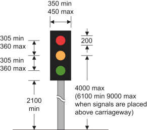 | Where the layout or character of the road restricts the visibility of the signals shown in the diagram, the maximum height of 4000 mm may be increased as appropriate to a maximum of 6100 mm | 1, 2, 3 | 2, 3, 4, 5, 43, 46 |
| 2 | Diagram 3000.1 Portable traffic light signals for the control of vehicular traffic | 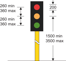 | 1, 2, 3 | 5, 6, 42, 43 | |
| 3 | Diagram 3000.2 Traffic light signals for the control of vehicular traffic consisting solely of pedal cycles (Alternative types) | 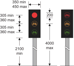 | 1, 2, 3 | 2, 3, 5, 43, 46 | |
| 4 | Diagram 3000.2A Traffic light signals for the control of vehicular traffic consisting solely of pedal cycles (Alternative types) | 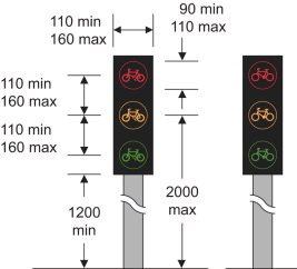 | 1, 2 | 2, 3, 5, 43, 46 | |
| 5 | Diagram 3014 Light signals for the control of road traffic at level crossings, swing or lifting bridges, airfields or in the vicinity of premises used regularly by fire and rescue authority, Scottish Fire and Rescue Service, police or ambulance vehicles | 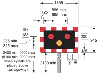 | 1, 2, 3 | 2, 4, 5, 46 | |
| 6 | Diagram 773 The light signals provided for at item 5 are ahead (where those light signals are at level crossing, swing or lifting bridge, or airfields) | 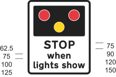 | 1. A distance may be added 2. An arrow pointing horizontally to the left or to the right may be added | 7 | |
| 7 | Diagram 563.1 The light signals provided for at item 5 are ahead (where those light signals are in the vicinity of premises used regularly by fire and rescue authority, Scottish Fire and Rescue Service, police or ambulance vehicles) | 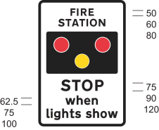 | 1. “FIRE” may be varied to: (a) “AMBULANCE”; (b) “POLICE”; (c) “FIRE AND AMBULANCE”; (d) “FIRE AND POLICE”; (e) “POLICE AND AMBULANCE”; or (f) “FIRE, POLICE AND AMBULANCE” 2. A distance may be added 3. An arrow pointing horizontally to the left or to the right may be added | 8 | |
| 8 | Diagrams 776 and 777 Another train or tramcar may be about to pass over the crossing. Level crossing ahead is crossed by more than one railway or tramway track, and more than one train or tramcar may pass over it in quick succession |  | “TRAIN” may be varied to “TRAM” | 14 (in respect of the sign shown by the diagram numbered 776 only) | 9 |
| 9 | Diagram 4002.1 Farside light signals for pedestrians |  | 3 | 3, 5, 10, 41, 42, 43, 46 | |
| 10 | Diagram 4002.1A Pedestrian countdown unit indicating to pedestrians the time remaining to cross the road (shown in combination with the signal provided for at item 19) |  | 1. Numerals may be varied 2. The positions of the countdown unit and green cycle aspect may be reversed 3. The cycle aspect may be omitted | 3, 5, 10, 42, 43 | |
| 11 | Diagram 4003 Instructions to pedestrians above the push button control for calling up pedestrian phases at traffic light signals |  | The legend ‘WAIT’ may be illuminated in white or yellow | 3, 5, 11 ,42, 43, 46 | |
| 12 | Diagram 4003.8 Instructions to road users for calling up pedestrian, equestrian or cyclist phases at traffic light signals | 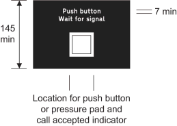 | 3, 12, 42, 43, 46 | ||
| 13 | Diagram 4003.1 Nearside light signals and instructions for pedestrians at a pedestrian facility controlled by traffic light signals | 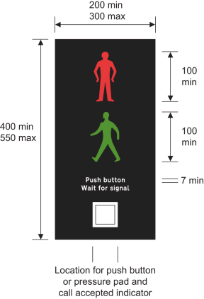 | 1. The symbols may be reversed 2. The legend ‘stand on mat’ may be added between the legends ‘push button’ and ‘wait for signal’ 3. The horizontal positions of the red and green symbols may be varied independently of each other 4. Multiple red and green symbols may be provided 5. The face containing the signal and instructions may be curved and may comprise more than one unit | 3, 5, 13, 42, 43, 46 | |
| 14 | Diagram 4003.1A Supplementary nearside light signals for pedestrians a pedestrian facility controlled by traffic light signals | 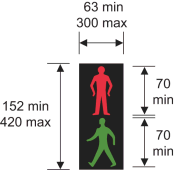 | 1. The symbols may be reversed 2. The horizontal positions of the red and green symbols may be varied independently of each other 3. The face containing the signal may be curved | 3, 5, 14, 43, 46 | |
| 15 | Diagram 4003.2 Farside light signals for equestrian traffic | 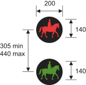 | The symbols may be reversed | 3 | 3, 5, 15, 41, 43, 46 |
| 16 | Diagram 4003.3 Instructions to horse riders above the push button control for calling up equestrian traffic phases at traffic light signals | 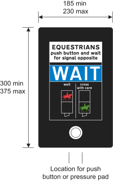 | The legend ‘WAIT’ may be illuminated in white or yellow | 3, 5, 16, 43, 46 | |
| 17 | Diagram 4003.4 Nearside light signals and instructions for horse riders at an equestrian traffic crossing facility controlled by traffic light signals | 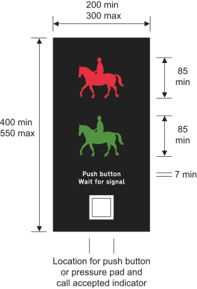 | 1. The symbols may be reversed 2. The horizontal positions of the red and green ridden horse symbols may be varied independently of each other 3. Multiple red and green ridden horse symbols may be provided. 4. The face containing the signal and instructions may be curved and may comprise more than one unit | 3, 5, 17, 41, 43, 46 | |
| 18 | Diagram 4003.4A Supplementary nearside light signals for horse riders at an equestrian traffic crossing facility controlled by traffic light signals | 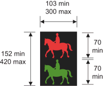 | 1. The symbols may be reversed where appropriate 2. The horizontal positions of the red and green ridden horse symbols may be varied independently of each other 3. The face containing the signal may be curved | 3, 5, 18, 43, 46 | |
| 19 | Diagram 4003.5 Farside light signals for pedestrians and cyclists at a Toucan crossing | 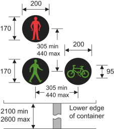 | The cycle aspect may be positioned to the left of the green pedestrian aspect | 3 | 3, 5, 19, 41, 43, 46 |
| 20 | Diagram 4003.6 (a) instructions to pedestrians and cyclists above the push button control for calling up pedestrian and cycle phases at a Toucan crossing; or (b) instructions to cyclists above the push button control for calling up cycle phases at a crossing controlled by the traffic light signals provided for at item 3 or 4 | 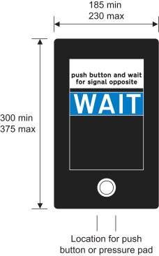 | The legend ‘WAIT’ may be illuminated in white or yellow | 3, 5, 20, 43, 46 | |
| 21 | Diagram 4003.7 Nearside light signals and instructions for pedestrians and cyclists at a Toucan crossing | 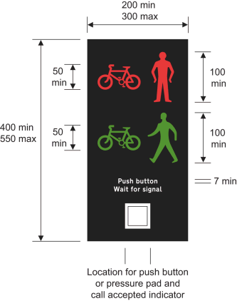 | 1. The combined cycle and pedestrian symbols may be reversed in a mirror image 2. The face containing the signal and instructions may be curved and may comprise more than one unit | 3, 5, 21, 41, 43, 46 | |
| 22 | Diagram 4003.7A Supplementary nearside signals for pedestrians and cyclists at a Toucan crossing | 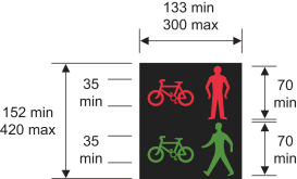 | 1. The combined cycle and pedestrian symbols may be reversed in a mirror image 2. The face containing the signal may be curved | 3, 5, 22, 43, 46 | |
| 23 | Diagram 4004 Signals placed at or near a school crossing place where children likely to be crossing the road on their way to or from school ahead (Alternative types) | 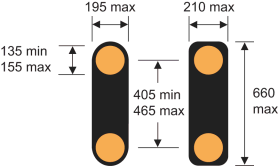 | The container may be coloured grey | 5, 23 | |
| 24 | Diagram 605.3 School crossing patrol sign | 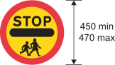 | 1, 2, 12 | ||
| 25 | Diagram 4005 A cattle crossing lies ahead and may be in use | 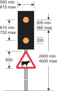 | 3 | 5, 24 | |
| 26 | Diagram 4006 Light signal at level crossing for pedestrians conveying the prohibition that pedestrians must not proceed beyond the marking provided for at item 68 | 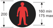 | 3 | 5, 25, 46 | |
| 27 | Diagram 4007 Yellow or fluorescent yellow globe to indicate presence of a Parallel, or Zebra crossing | 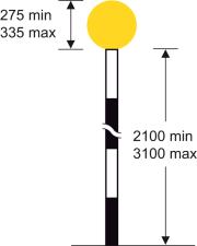 | 13 | ||
| 28 | Diagram 543 Traffic signals ahead | 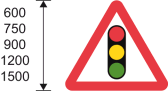 | |||
| 29 | Diagram 543.1 Traffic signals in the direction indicated which only operate at certain times (Supplementary plate) |  | 1. “Part time signals” may be varied to “Peak hour signals” or “Traffic control” or omitted 2. The sign may show a different distance or the distance may be omitted 3. The arrow may be reversed to point horizontally to the right or omitted 4. When “Part time signals” is omitted, the x-height of the legend may be varied to 200 mm | 26 | |
| 30 | Diagram 544 Zebra crossing or Parallel crossing ahead | 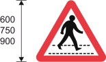 | |||
| 31 | Diagram 547.8 Zebra crossing, Parallel crossing, or signal‑controlled crossing on a road hump, in the direction indicated (Supplementary plate) |  | 1. “Humped crossing” may be varied to “Zebra crossing” or “Parallel crossing” or omitted 2. The sign may show a different distance or the distance may be omitted 3. The arrow may be reversed to point horizontally to the right or omitted 4. When “Humped crossing” is omitted, the x-height of the legend may be varied to 150 mm or 200 mm | 27 | |
| 32 | Diagrams 5001.1 and 5001.2 Lane open to vehicular traffic (Alternative types) | 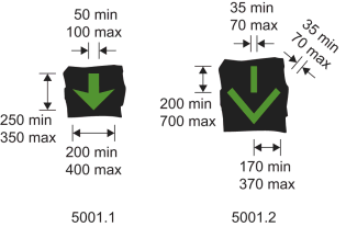 | 5, 28, 46 | ||
| 33 | Diagrams 5003 and 5003.1 Lane closed to vehicular traffic (Alternative types) | 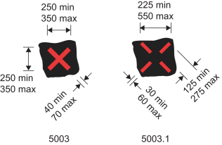 | 5, 28, 46 | ||
| 34 | Diagrams 5005 and 5005.1 Lane closed ahead and vehicular traffic should move to the next lane on the left (Alternative types) | 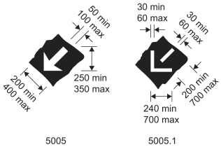 | 5, 28, 46 | ||
| 35 | Diagram 5010 The lane control light signals provided for at items 32, 33 and 34 ahead | 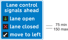 | The diagonal white arrow symbol and the words ‘move to left’ may be omitted where the signals provided for at item 34 are not used in the lane control system | 8 | |
| 36 | Diagram 5011 The lane control light signals provided for at items 32, 33 and 34 ahead on a road extending from a junction | 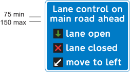 | The diagonal white arrow symbol and the words ‘move to left’ may be omitted where the signals provided for at item 34 are not used in the lane control system | 8 | |
| 37 | Diagram 5012 System of lane control light signals ahead | 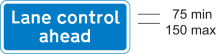 | |||
| 38 | Diagram 5013 Direction of a system of lane control light signals | 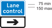 | The direction of the arrow may be varied with the arrow or chevron pointing horizontally to the left | ||
| 39 | Diagram 5014 Distance to and direction of a system of lane control light signals (alternative types) | 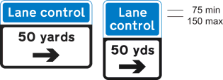 | 1. The sign may show a different distance 2. The arrow may point horizontally to the left or may be omitted | ||
| 40 | Diagram 5015 End of a system of lane control light signals | 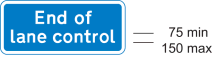 | |||
| 41 | Diagram 548.1A Supervised cattle crossing ahead | 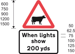 | 1. The sign shown in the lower part of the diagram may show a different distance 2. An arrow pointing to the left or to the right may be added to the sign shown in the lower part of the diagram | ||
| 42 | Diagram 606 Vehicular traffic may proceed only in the direction indicated by the arrow (Alternative types) |  | The diameter may be not less than 95 mm and not more than 110 mm if the sign is placed in conjunction with the sign provided for at item 4 | 10 | 28, 29 |
| 43 | Diagrams 612, 613 and 614 No right, left, or u-turn for vehicular traffic (Alternative types) | 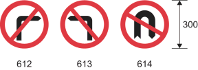 | The diameter may be not less than 95 mm and not more than 110 mm if the sign is placed in conjunction with the sign provided for at item 4 | 10 | 28, 29 |
| 44 | Diagram 616 No entry for vehicular traffic | 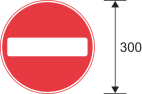 | 10 | 28, 30 | |
| 45 | Diagrams 954.5, 954.6 and 954.7 Classes of vehicle excluded from restriction or prohibition conveyed by associated sign (Alternative types) | 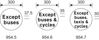 | The legend may be varied to “Except” and “cycles”, “local buses”, “buses & taxis”, local buses & cycles” or “local buses & taxis” | 10 | 28 |
| 46 | Diagram 1001 Vehicular traffic must not proceed beyond the line when required to stop by light signals, by a constable in uniform or by a traffic warden |  | 4, 5 | 31, 42, 43 | |
| 47 | Diagram 1001.1 Tramcars must not proceed beyond the line when required to stop by light signals |  | 4 | 32 | |
| 48 | Diagram 1001.2 Alternatives to the stop line provided for at item 46 showing separate stop lines for pedal cycles proceeding in the cycle lane | 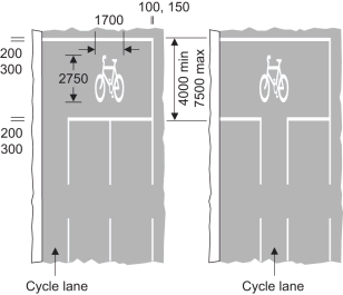 | 1. The number of traffic lanes may be varied 2. The nearside cycle lane may be bounded by the continuous white line provided for at item 7 of the sign table in Part 6 of Schedule 9 3. The right hand longitudinal line may be omitted where that part of the carriageway is delineated by a raised kerb | 4, 5 | 33 |
| 49 | Diagram 1001.2B Alternative to the stop line provided for at item 46 showing separate stop lines for pedal cycles. | 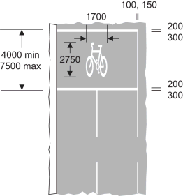 | 1. The number of traffic lanes may be varied 2. The right hand longitudinal line may be omitted where that part of the carriageway is delineated by a raised kerb | 4, 5 | 33 |
| 50 | Diagram 1001.2A Alternatives to the stop line provided for at item 46 showing a separate stop line at a junction for pedal cycles proceeding through the cycle entry | 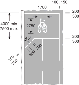 | 1. The number of traffic lanes may be varied 2. The right hand longitudinal line may be omitted where that part of the carriageway is delineated by a raised kerb 3. The number of marks in the diagonal line may be varied | 4, 5 | 33 |
| 51 | Diagram 1001.3 Zig-zag lines to indicate requirements or prohibitions relating to stopping or overtaking at a Puffin crossing, signal-controlled crossing facility or portable signal-controlled pedestrian facility (shown in combination with the markings provided for at items 46 and 55) | 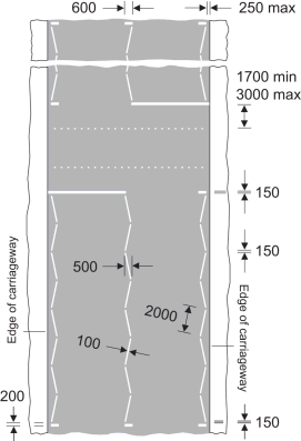 | 1. Subject to entry 4, each zig-zag line may contain more than 8 marks but not more than 18 marks 2. The central zig-zag line may be reversed, or where the road is not more than 6 metres wide, may be omitted 3. Each zig-zag line need not contain the same number of marks as any other line, provided each mark is of the same length as the others 4. Where the traffic authority is satisfied that the layout or character of the road means it is not practical to lay 8 marks, the number of marks can be reduced to not less than 2 5. Where there is a central refuge or reservation in the carriageway the zig-zag lines may be marked on each side of the refuge or reservation provided that the markings on each side are indicated as separate crossings 6. Where a central refuge or reservation is provided, the markings provided for at item 23 of Part 4 of Schedule 11 (and shown in the second diagram of that item) may be placed between the zig-zag lines on the approaches 7.The zig-zag lines may to be placed up to 2 metres from the edge of the carriageway to allow cyclists to ride on the nearside of the lines | 1, 2, 5 | 34, 42, 43 |
| 52 | Diagram 1001.4: Zig-zag lines to indicate the requirements or prohibitions relating to stopping or overtaking at a Zebra crossing (shown in combination with the marking provided for at item 54, the stripes provided for at paragraph 18 of Part 1 and the marking provided for at item 55) | 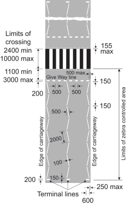 | 1. Subject to entry 4, each zig-zag line may contain more than 8 marks but not more than 18 marks 2. The central zig-zag line may be reversed, or where the road is not more than 6 metres wide, may be omitted 3. Each zig-zag line need not contain the same number of marks as any other line, provided each mark is of the same length as the others 4. Where the traffic authority is satisfied that the layout or character of the road means it is not practical to lay 8 marks, the number of marks can be reduced to not less than 2 5. Where there is a central refuge or reservation in the carriageway the zig-zag lines may be marked on each side of the refuge or reservation, as the case may be, provided that the marking on each side are indicated as separate crossings 6. Where a central refuge or reservation is provided, the markings provided for at item 23 of the table in Part 4 of Schedule 11 and shown in the bottom diagram at that item (vehicular traffic not to enter part of the carriageway) may be placed between the zig-zag lines on the approaches. 7.The zig-zag lines may to be placed up to 2 metres from the edge of the carriageway to allow cyclists to ride on the nearside of the lines 8. The marking provided for at item 55 may be omitted 9. The maximum distance of 3 metres between the give-way line and the limits of the crossing may, if the traffic authority thinks fit, be increased to not more than 10 metres | 1, 2 | |
| 53 | 1001.5 Zig-zag lines to indicate the requirements or prohibitions relating to stopping or overtaking at a Parallel pedestrian and cyclist crossing (shown in combination with markings provided for at items 54 and 57 and the stripes provided for at paragraph 18 of Part 1) | 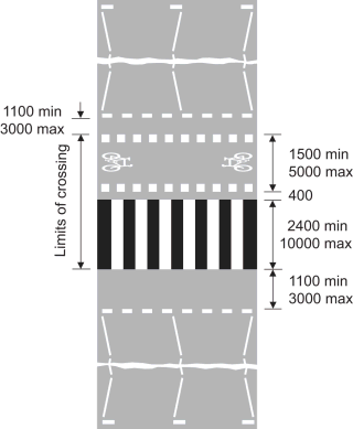 | 1. Subject to entry 4, each zig-zag line may contain more than 8 marks but not more than 18 marks. 2. The central zig-zag line may be reversed, or where the road is not more than 6 metres wide, may be omitted 3. Each zig-zag line need not contain the same number of marks as any other line, provided each mark is of the same length as the others 4. Where the traffic authority is satisfied that the layout or character of the road means it is not practical to lay 8 marks, the number of marks can be reduced to not less than 2 5. Where there is a central refuge or reservation in the carriageway the zig-zag lines may be marked on each side of the refuge or reservation, as the case may be, provided that the marking on each side are indicated as separate crossings 6. Where a central refuge or reservation is provided, the markings provided for at item 23 of the table in Part 4 of Schedule 11 and shown in the bottom diagram at that item (vehicular traffic not to enter part of the carriageway) may be placed between the zig-zag lines on the approaches 7. The zig-zag lines may to be placed up to 2 metres from the edge of the carriageway to allow cyclists to ride on the nearside of the lines 8. The cycle symbols may be omitted or reversed as appropriate | 1, 2 | |
| 54 | Diagram 1001.5 Give-way marking for use at Zebra crossings, and Parallel pedestrian and cyclist crossings | 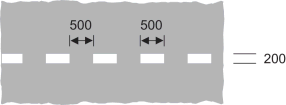 | |||
| 55 | Diagram 1055.1 (a) a place suitable for pedestrians to cross a road at which traffic is subject to control by a constable in uniform or by a traffic warden, being control which is normally in operation during periods amounting in aggregate to not less than 20 hours in any week; (b) the most suitable place for pedestrians to cross a carriageway within 10 metres of the traffic signals provided for at item 1; (c) place suitable for cyclists to cross a road at which cyclists are controlled by traffic light signals of the kind provided for at item 3 or 4, and other vehicular traffic is controlled by traffic signals of the kind provided for at item 1; (d) place suitable for pedestrians to cross at a signal (including portable) controlled pedestrian facility; (e) place suitable for pedestrians and cyclists to cross at a Toucan crossing; (f) place suitable for crossing at an equestrian only crossing; or (h) place suitable for pedestrians to cross forming part of a Zebra crossing | 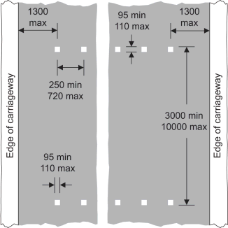 | 1. The square marks may be varied to circular marks with a diameter between 95 mm and 110 mm 2. The square marks, or the circular marks referred to at 1, may be varied to square or circular non-depressible studs of the same size and shape which are coloured white, silver or light grey provided the studs are not fitted with reflectors, retroreflecting material or a light source 3. The number of marks may be varied according to the width of the road 4. The minimum width of the crossing, other than a Toucan crossing, may be reduced from 3000 mm to 2400 mm | 42, 43 | |
| 56 | Diagram 1055.2 As for the description in this column of item 55, paragraph (c) (d) or (e), with an additional crossing point for equestrians | 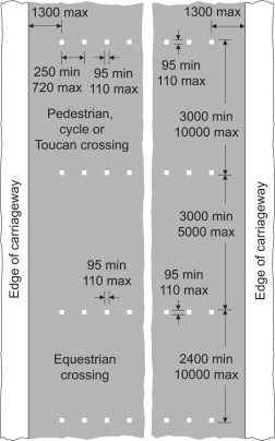 | 1. The square marks may be varied to circular marks with a diameter between 95 mm and 110 mm 2. The square marks, or the circular marks referred to at 1, may be varied to square or circular non-depressible studs of the same size and shape which are coloured white, silver or light grey provided the studs are not fitted with reflectors, retroreflecting material or a light source 3. The number of marks may be varied according to the width of the road 4. The minimum width of the crossing, not being a Toucan crossing, may be reduced from 3000 mm to 2400 mm | 43 | |
| 57 | Diagram 1055.3 (a) route for vehicular traffic consisting solely of pedal cyclists across a signal controlled junction (b) route for vehicular traffic consisting solely of pedal cyclists across a Parallel crossing | 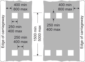 | The marking may be varied to include the symbol shown in the diagram at item 28 of the sign table in Part 4 Schedule 11 (cycle symbol) | 35 | |
| 58 | Diagram 7011 Point beyond which vehicular traffic must not proceed when required to stop (in accordance with the provisions of Part 1) at portable light signals provided for at item 2 when the road marking provided for at item 46 is not placed on the carriageway | 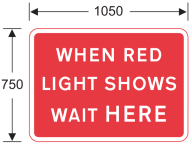 | The legend may be varied as follows— (a) “WHEN STOP SIGN SHOWS WAIT HERE”; (b) “WHEN RED LIGHT SHOWS WAIT HERE FOR CONVOY VEHICLE”; (c) “WHEN STOP SIGN SHOWS WAIT HERE FOR CONVOY VEHICLE”; (d) “WHEN GREEN LIGHT SHOWS FOLLOW CONVOY VEHICLE”; or (e) “AT TRAFFIC CONTROL FOLLOW CONVOY VEHICLE” | 8 | |
| 59 | Diagram 7011.1 As for item 58 where there is a road junction | 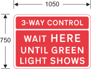 | ‘3-WAY’ may be varied to ‘4-WAY’ | 8 | |
| 60 | Diagram 7011.2 Instruction to vehicular traffic at a portable signal-controlled pedestrian facility | 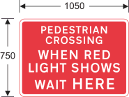 | 8 | 42, 43 | |
| 61 | Diagram 7019 Traffic light signals not in use | 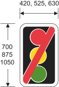 | |||
| 62 | Diagram 7021 Traffic on road ahead is being controlled by portable light signals (indication to traffic joining that road) | 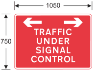 | 8 | ||
| 63 | Diagram 7022 Traffic joining a length of road being controlled by portable light signals is not controlled by such signals | 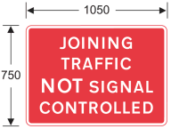 | |||
| 64 | Diagram 7023 Vehicular traffic must not proceed into a length of road where one-way working is temporarily necessary (manually operated sign) | 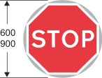 | 1, 6, 9 | 36 | |
| 65 | Diagram 7024 Vehicular traffic may proceed into a length of road where one-way working is temporarily necessary (manually operated sign) |  | 6, 9 | 36 | |
| 66 | Diagram 7031 Vehicular traffic must not proceed beyond the sign when displayed for a short period during works on or near an all‑purpose road (Double sided sign) | 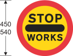 | A red or transparent protective strip, with a visible width not exceeding 6 mm, may be applied to the perimeter of the sign | 1, 7, 11 | 37, 38 |
| 67 | Diagram 790 New method of controlling traffic at a railway or tramway level crossing ahead – temporary sign | 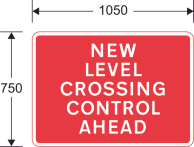 | “CONTROL” may be omitted | 39 | |
| 68 | Diagram 1003.2 Pedestrians approaching a level crossing must wait behind the line when the barriers are closed or when the red figure in the sign provided for at item 26 or the light signals provided for at item 5 are showing or, if there are neither barriers nor light signals, until satisfied that it is safe to proceed | 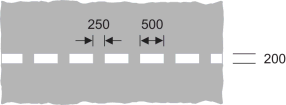 | |||
| 69 | Diagram 545.1 Part-time advisory 20 mph speed limit at or near a school | 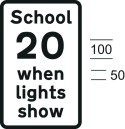 | 40 |
PART 3Green arrow, tram and cycle signals

Sign table – Schedule 14, Part 3
(1) Item | (2) Description | (3) Diagram | (4) Permitted location and variations |
|---|---|---|---|
| 1 | Diagrams 3001.2 and 3001.3 Green arrow to show the direction for vehicular traffic to take for inclusion in traffic light signals as described in Part 1 |  | 1. Diagram A: can be placed in positions 1, 2, 3, 4 2. Diagram B: can be placed in positions 2, 3 3. Diagram C: can be placed in positions 1, 2, 3, 4, 5 4. Diagram D: can be placed in positions 2, 3 |
| 2 | Diagram 3013 Light signal for control of tramcars (diagram shows the light signal fully illuminated- see items 3 to 7 for the illumination of the signal to convey particular descriptions) | 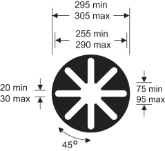 | 1. Diagram A: can be placed in positions 1, 2, 3, 4 2. Diagram B: can be placed in positions 1, 2, 3 3. Diagram C: can be placed in positions 1, 2, 4, 5 4. Diagram D: can be placed in positions 1, 3 |
| 3 | Diagram 3013.1 Tramcar must not proceed beyond the stop line |  | |
| 4 | Diagram 3013.2 Tramcar may proceed beyond the stopline and proceed straight ahead | 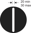 | |
| 5 | Diagram 3013.3 Tramcar may proceed beyond the stopline and proceed to the left |  | |
| 6 | Diagram 3013.4 Tramcar may proceed beyond the stopline and proceed to the right |  | |
| 7 | Diagram 3013.5 Tramcar must not proceed beyond the stop line except that, as respects a tramcar which is so close to the stop line that it cannot safely be stopped without proceeding beyond the stop line, it conveys the same indication as the aspect which was shown immediately before it | 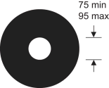 | |
| 8 | Diagram 3001.4 Green cycle signal for inclusion in traffic light signals as described in Part 1 |  | 1. Diagram A: can be placed in position 2 2. Diagram B: can be placed in position 2 3. Diagram C: can be placed in position 2 4. Diagram D: can be placed in position 3 |
PART 4Requirements applying to signs in Parts 2 and 3
1. Section 36 of the 1988 Act applies to the sign.
2. The sign is specified for the purposes of column 5 of the entry in Schedule 2 to the Road Traffic Offenders Act 1988(94) relating to offences under section 36 of the 1988 Act.
3. The dimension of 200 mm referred to in the diagram for the sign may be varied by—
(a)up to 10% where the varied dimension is greater than 200 mm, or
(b)up to 2.5% where the varied dimension is less than 200 mm,
provided that, where the dimensions of a signal which displays an arrow or symbol are varied in accordance with this paragraph, the dimensions chosen for the arrow or symbol are such as to maintain the shape and proportions shown in the diagram in which the signal is shown.
4. The stop line must be reflectorised unless paragraph 5 applies.
5. If the stop line is placed with zig-zag lines the stop line may be reflectorised.
6. The sign comprises the stop (item 64) and go (item 65) symbols on opposite sides of the same sign.
7. No retroreflecting material must be applied to that part of the sign which is coloured fluorescent yellow, unless the retroreflecting material is applied to that part in horizontal strips with a gap between each strip, or unless the retroreflecting material is itself also fluorescent.
8. Where the sign is erected on a road subject to a speed limit greater than 20 mph and is within 50 metres of any lamp which forms part of a system of street-lighting, the illumination requirements for the sign are–—
(a)where that system of street-lighting is illuminated throughout the hours of darkness, the sign must be illuminated by internal or external lighting for so long as that system is illuminated and may also be reflectorised; or
(b)where that system of street-lighting is not illuminated throughout the hours of darkness—
(i)the sign must be illuminated by internal or external lighting for so long as that system is illuminated and must also be reflectorised; or
(ii)the sign must be illuminated throughout the hours of darkness by internal or external lighting and may also be reflectorised.
9. The sign must be illuminated throughout the hours of darkness by internal or external lighting and may also be reflectorised.
10. The sign must be illuminated by means of internal lighting at all times except when the light signals to which it is fixed are being maintained or repaired.
11.—(1) Subject to sub-paragraphs (2) and (3), the parts of the sign not coloured black must be reflectorised.
(2) The part of the sign coloured yellow must be fluorescent, unless the retroreflecting material is applied to that part in horizontal strips with a gap between each strip or the retroreflecting material is itself also fluorescent.
(3) The part of the sign coloured red may be fluorescent.
12.—(1) The illumination of the roundel must be in accordance with this paragraph.
(2) The parts of the roundel coloured black must not be illuminated by means of retroreflecting material.
(3) Subject to sub-paragraph (4), the parts of the roundel coloured yellow must be either fluorescent or illuminated by means of internal lighting.
(4) Subject to sub-paragraph (5) with the exception of the parts of the roundel coloured black and any protective strip applied to the perimeter of the roundel, the roundel must be illuminated by means of retroreflecting material and any such material applied to the parts coloured yellow must, if not fluorescent, be applied in horizontal strips with gaps between the strips.
(5) The parts of the roundel coloured red may be fluorescent or illuminated by means of internal lighting.
13.—(1) A globe must be internally illuminated by a flashing light except that, where sub-paragraph (2) applies, it may be a steady light.
(2) This sub-paragraph applies where—
(a)in relation to a globe placed in England and Wales, the Secretary of State; or
(b)in relation to a globe placed in Scotland, Scottish Ministers,
has or have given authorisation in writing for the light to be steady.
(3) Where a globe is mounted on or attached to or mounted on a post, whether or not specially provided for the purpose—
(a)the post must be coloured in alternate black and white bands with the lowest band being coloured black;
(b)the width of the bands must be not less than 275 mm, nor more than 335 mm, save that the lowest band may be of a width of not more than 1 metre; and
(c)the post may be internally illuminated.
(4) A globe, or the post on which it is mounted, may be fitted with all or any of the following—
(a)a backing board or other device designed to improve the conspicuousness of the globe;
(b)a shield or other device designed to prevent or reduce light shining into adjacent premises; or
(c)a light to illuminate the crossing.
14. The sign must only be illuminated when the warning conveyed by the sign applies.
PART 5Movement at section 25 crossings
1. The driver of a vehicle must not cause the vehicle or any part of it to stop within the limits of a section 25 crossing unless prevented from proceeding by circumstances beyond the driver’s control or it is necessary to stop to avoid injury or damage to persons or property.
2. A pedestrian must not remain on the carriageway within the limits of a section 25 crossing longer than is reasonably necessary for that pedestrian to pass over the crossing with reasonable despatch.
3. Subject to paragraph 4, the driver of a vehicle must not cause it, or any part of it, to stop in a section 25 crossing controlled area.
4.—(1) The prohibition in paragraph 3 does not apply to—
(a)a pedal cycle; or
(b)a driver who stops a vehicle in a controlled area in any of the circumstances specified in sub-paragraph (2).
(2) The circumstances are—
(a)the driver has stopped the vehicle for the purpose of complying with paragraph 7(1);
(b)the driver has stopped the vehicle for the purpose of complying with an indication given by a light signal for the control of vehicular traffic or the direction of a constable in uniform, a traffic officer in uniform or a traffic warden;
(c)the driver is prevented from proceeding by circumstances beyond the driver’s control or it is necessary to stop to avoid injury or damage to persons or property;
(d)the vehicle is being used for at least one of the following purposes—
(i)fire and rescue authority;
(ii)Scottish Fire and Rescue Service;
(iii)ambulance;
(iv)blood service;
(v)providing a response to an emergency at the request of an NHS ambulance service;
(vi)bomb or explosive disposal;
(vii)special forces;
(viii)police;
(ix)National Crime Agency.
(e)the vehicle is stopped for no longer than is necessary for it to be used for the purposes of—
(i)an operation involving building, demolition or excavation;
(ii)the removal of any obstruction to traffic;
(iii)the maintenance, improvement or reconstruction of a road; or
(iv)the laying, erection, alteration, repair or cleaning in or near the controlled area of any sewer, or of any main, pipe or apparatus for the supply of gas, water or electricity, or of any electronic communications apparatus kept installed for the purposes of an electronic communications code system or of any other electronic communications apparatus lawfully kept installed in any position,
but only if the vehicle cannot be used for those purposes without stopping in the controlled area;
(f)the vehicle is a public service vehicle being used—
(i)in the provision of a local service; or
(ii)to carry passengers for hire or reward at separate fares,
where the vehicle is waiting in the controlled area in order to take up or set down passengers having proceeded past the crossing or the light signals to which the controlled area relates; or
(g)the vehicle is stopped for the purpose of making a left or right turn.
5. When vehicular light signals at a Puffin crossing are displaying a light signal which conveys a prohibition described at paragraph 5(2) of Part 1, the driver of a vehicle must not cause it to contravene that prohibition.
6.—(1) Whilst any motor vehicle (“the approaching vehicle”) or any part of it is within the limits of a section 25 crossing controlled area and is proceeding towards the crossing to which the controlled area relates, the driver of the vehicle must not cause it or any part of it to pass ahead of the foremost part of—
(a)any other motor vehicle proceeding in the same direction
(b)a vehicle which is stationary for the purpose of complying with paragraph 5 or 7.
(2) In sub-paragraph (1)—
(a)the reference to a motor vehicle in paragraph (a) is, in a case where more than one motor vehicle is proceeding in the same direction as the approaching vehicle in a section 25 crossing controlled area, a reference to the motor vehicle nearest to the crossing to which the controlled area relates; and
(b)the reference to a stationary vehicle is, in a case where more than one vehicle is stationary in a controlled area for the purpose of complying with paragraph 5 or 7, a reference to the stationary vehicle nearest the crossing to which the controlled area relates.
7.—(1) Every pedestrian who is on the carriageway within the limits of a Zebra crossing, which is not for the time being controlled by a constable in uniform or traffic warden, before any part of a vehicle has entered those limits has precedence within those limits over that vehicle and the driver must accord such precedence to any such pedestrian.
(2) Where there is a refuge for pedestrians or central reservation on a Zebra crossing, the parts of the crossing situated on each side of the refuge or central reservation are, for the purposes of this paragraph, to be treated as separate crossings.
PART 6The Schedule 14 General Directions
1. In these General Directions a reference to an item is to an item in the Part 2 sign table (except where a contrary intention is expressed).
2.—(1) Subject to sub-paragraph (3), the traffic light signals provided for at item 1, 3 or 4 may only be placed in conjunction with the road marking provided for at item 46, 47, 48, 49 or 50 (the reference to item 47 is to be ignored in relation to item 4).
(2) Subject to sub-paragraph (3), the light signals provided for at item 5 may only be placed in conjunction with the road marking provided for at item 46.
(3) Sub-paragraphs (1) and (2) do not apply to light signals while works which necessitate the temporary removal of a road marking are being executed on a road near the light signals.
3.—(1) This paragraph applies where—
(a)one or more of the signs provided for at item 1, 3 or 4;
(b)one or more of the signs provided for at items 9 to 22; or
(c)a combination of the signs mentioned at (a) and (b),
are mounted on a post or other support specially provided for the purpose.
(2) No other signs may be mounted on, or fixed to, that post or support.
(3) Sub-paragraph (2) is subject to sub-paragraphs (4) to (6)
(4) One of each of the signs provided for at items 42 to 45 may be fixed to any traffic light signals on that post or support as long as those signs are placed so that they face the stream of traffic to which they are intended to convey their warning, information, requirement, restriction or prohibition.
(5) A sign which are referred to in paragraph (6) may be mounted on the post or support as long as it is placed so that it faces the stream of traffic to which it is intended that that information is conveyed.
(6) The signs are—
(a)those provided for at item 29 (where the legend is “Part time signals” or “Peak hour signals”) or 61;
(b)a sign placed by virtue of Part 9 of Schedule 13 conveying the information that traffic light signals are not in use.
4. The traffic light signals may be placed to face traffic proceeding in a particular direction if and only if—
(a)at least two identical sets of signals are placed so as to face traffic proceeding in that direction; and
(b)at least one of those sets of signals is a set of primary signals.
5.—(1) The light signals may only be placed if they are placed so that they face the stream of traffic to which they are intended to convey the warnings, information, requirements, restrictions or prohibitions prescribed.
(2) A container enclosing the lamps of the light signals must be coloured black except that—
(a)if a container encloses lamps of the light signals provided for at item 23, 25, 32, 33 or 34 it may be coloured grey instead of black;
(b)the back of a container enclosing the light signals provided for at item 11 to 14, 16 to 18 or 20 to 22 may be coloured yellow; and
(c)the container may have a white border not less than 45 nor more than 55 mm wide.
(3) The light signals other than the signals provided for at item 5 may be mounted on a backing board, which must be coloured black and may have a white border not less than 45 nor more than 55 mm wide.
(4) In the case of the light signals provided for at item 5, the back of the backing board may be coloured black or grey.
(5) Where the light signals are mounted on a post specially provided for the purpose, that part of the post which extends above ground level must either be coloured grey, black, brown, dark green or dark blue or be in a non-reflective metallic finish.
(6) Despite sub-paragraph (5)—
(a)the post may be marked with a yellow or white band not less than 140 nor more than 160 mm deep and the lower edge of the band being not less than 1500 nor more than 1700 mm above ground level; and
(b)where the light signals provided for at item 1, 3, 4, 9 to 11 or 13 to 22 are installed temporarily, the containers in which the posts are placed may be coloured with alternate red and white horizontal stripes.
(7) The portable light signals provided for at item 2 and the signals provided for at items 9 to 13 when used at a portable crossing, instead of being mounted on a post coloured in accordance with sub-paragraph (5), may be mounted on a post coloured yellow (but having no yellow or white band as specified in sub-paragraph (6)) or on a tripod or other support coloured yellow.
6.—(1) A traffic authority may, pursuant to section 65(1) of the 1984 Act, cause or permit the placing of the portable light signals if and only if—
(a)permission is given in writing, or in a case of urgency, given orally and confirmed in writing as soon as reasonably practicable thereafter; and
(b)either—
(i)the written permission of the authority includes express approval to the placing of the signals at a particular site; or
(ii)the authority is satisfied that the circumstances of the particular case fall within one of the sets of circumstances specified in sub-paragraph (2).
(2) The sets of circumstances referred to in sub-paragraph (1)(b)(ii) are—
(a)where the signals are to be operated and maintained by, and are under the regular supervision of, a constable in uniform during the progress of a temporary scheme of traffic control;
(b)where the signals are placed on a length of road along which—
(i)there is no junction carrying vehicular traffic to or from it; and
(ii)the width of the carriageway is temporarily restricted so as to carry only one line of traffic;
(c)where the signals are placed at a level crossing when work in relation to that crossing is being carried out;
(d)where the signals are placed on a road which is—
(i)adjacent to the temporary site of road, building or engineering works; and
(ii)is used for the movement of vehicles, materials, plant or equipment into and out of the site of the works.
(3) Nothing in this direction is to be taken to limit or affect the powers of a constable or the chief officer of police under section 67(1) of the 1984 Act (placing of temporary signs on roads in extraordinary circumstances).
7. The sign may only be placed in conjunction with a sign provided for at item 21, 46, 51, 52 or 53 of the sign table in Part 2 of Schedule 2 (and no plate may be placed with the signs).
8. The sign may only be placed in conjunction with the sign provided for at item 56 of the sign table in Part 2 of Schedule 2 (and no plate may be placed with the signs).
9. The light signal may only be placed at or near a level crossing and the legend on that light signal may be displayed only when a railway vehicle or tramcar has just passed over the level crossing and another is approaching.
10. The light signals may only be placed in conjunction with the light signals provided for at item 1 to 4.
11. The sign may only be placed in conjunction with the light signals provided for at item 9.
12. The sign may only be placed in conjunction with the light signals provided for at item 3, 4, 9, 15 or 19.
13. The light signals may only be placed in conjunction with—
(a)the light signals provided for at item 1, 2, 3 or 4; or
(b)the light signals mentioned at (a) and the light signals provided for at item 14.
14. The light signals may only be placed in conjunction with the light signals provided for at item 13 and those provided for at item 1, 3 or 4.
15. The light signals may only be placed in conjunction with the light signals provided for at item 1, 3 or 4.
16. The sign may only be placed in conjunction with the light signals provided for at item 15.
17. The light signals may only be placed in conjunction with—
(a)the light signals provided for at item 1, 3 or 4; or
(b)the light signals mentioned at (a) and those provided for at item 18.
18. The light signals may only be placed in conjunction with the light signals provided for at item 17 and those provided for at item 1, 3 or 4.
19. The light signals may only be placed in conjunction with the light signals provided for at item 1, 3 or 4.
20. The sign may only be placed in conjunction with the light signals provided for at item 3, 4 or 19.
21. The light signals may only be placed in conjunction with—
(a)the light signals provided for at item 1, 3 or 4; or
(b)the light signals mentioned at (a) and those provided for at item 22.
22. The light signals may only be placed in conjunction with the light signals provided for at item 21 and those provided for at item 1, 3 or 4.
23. The light signals may only be placed in conjunction with the sign provided for at item 25 of the table in Part 2 of Schedule 2, together with a plate bearing the legend “School”, “Patrol” or “Disabled children”.
24. The light signals may only be placed when the signs provided for at item 41 are placed in advance of those signals.
25. The light signals may only be placed in conjunction with the light signals provided for at item 5.
26. The sign may only be placed in conjunction with the sign provided for at item 28 or, where the legend is “Part time signals” or “Peak hour signals”, the light signals provided for at item 1, 3, or 4.
27. The sign may only be placed in conjunction with the sign provided for at item 28 or 30.
28. The signs may only be placed to indicate the effect of an Act, order, regulation, bylaw, resolution or notice which prohibits or restricts the use of the road by traffic.
29. The sign may only be placed in conjunction with the light signals provided for at item 1, 3 or 4.
30. The sign may only be placed in conjunction with the light signals provided for at item 1 or 3.
31.—(1) The road marking may only be placed in conjunction with the light signals provided for at item 1, 2, 3, 4 or 5.
(2) Despite sub-paragraph (1), the marking may be placed at a site where traffic is from time to time controlled by a constable in uniform or traffic warden without the light signals referred to in that sub-paragraph.
32. The road marking may only be placed—
(a)in conjunction with the traffic light signals provided for at item 1 or 3; and
(b)when the signal provided for at items 2 to 7 of the table in Part 3 (light signal for control of tramcars) is part of those traffic light signals.
33. The road marking may only be placed—
(a)in conjunction with the traffic light signals provided for at item 1; and
(b)when those signals are placed adjacent to the stop line appearing above the pedal cycle symbol that forms part of the marking.
34.—(1) Subject to sub-paragraph (2), the road marking may only be placed in conjunction with the traffic light signals provided for at item 1 together with—
(a)the marking provided for at item 55 or 56 (marks to show a suitable place for crossing); and
(b)the light signals provided for at item 9, 13 (whether or not used in conjunction with the light signals provided for at item 14), 15, 17 (whether or not used in conjunction with the light signals provided for at item 18), 19 or 21 (whether or not used in conjunction with the light signals provided for at item 22).
(2) The road marking may be placed in conjunction with the traffic light signals provided for at item 2 (portable traffic light signals), together with the light signals provided for at item 9 or 13 and the marking provided for at item 55 as part of a portable signal-controlled pedestrian facility where all streams of vehicular traffic are stopped only for the purpose of enabling pedestrians to cross the carriageway in conjunction with the traffic light signals.
35. The road marking may only be placed in conjunction with the light signals provided for at item 1, 3 or 4.
36. The signs may only be placed —
(a)where one-way working is necessary along a length of road because part of the width of the carriageway has been temporarily closed to traffic; and
(b)either—
(i)there is no junction with another road along that length; or
(ii)the traffic authority has given express written approval to the placing of the sign in relation to a length of road having a junction with another road.
37. The sign may only be placed in connection with the execution of works on or near a road, or a temporary obstruction.
38. The post provided for the mounting of the sign must be coloured in alternate black and yellow bands each 300 mm deep with a black band uppermost below the bottom of the sign face and the yellow bands may be reflectorised.
39. The sign—
(a)may only be placed in connection with works involving—
(i)an alteration in the layout of a level crossing; or
(ii)the placing, removal or alteration of signs on or near a level crossing; and
(b)may be retained in place not later than the end of the period of three months beginning with the day of the completion of those works.
40. The sign may only be placed in conjunction with—
(a)a sign provided for at item 23; and
(b)a sign provided for at item 25 of the sign table in Part 2 of Schedule 2.
41.—(1) Zig-zag lines must be placed on the approaches to each side of a relevant crossing facility so as to form controlled areas.
(2) In this general direction, “relevant crossing facility” means—
(a)a signal-controlled crossing facility—
(i)at which there is placed the signal provided for at item 9, 15, 17, 19 or 21; and
(ii)which is not situated at a junction at which the priority between motor vehicles is regulated by traffic light signals;
(b)a Puffin crossing;
(c)a Parallel crossing; or
(d)a Zebra crossing.
42.—(1) A traffic authority may, pursuant to section 65(1) of the 1984 Act, cause or permit the placing of a portable signal-controlled pedestrian facility if, and only if—
(a)permission is given in writing; and
(b)the written permission of the authority includes express approval to the placing of the facility at a particular site.
(2) Nothing in this direction is to be taken to limit or affect the powers of a constable or the chief officer of police under section 67(1) of the 1984 Act (placing of temporary signs on roads in extraordinary circumstances).
43.—(1) The placing of light signals and other signs at crossings must be in accordance with the sub-paragraphs (2) to (7).
(2) On the left hand side of the crossing there is to be placed a primary signal and on the right hand side of the crossing, refuge for pedestrians or central reservation, as the case may be, there is to be placed a further primary, or a secondary, signal.
(3) At each end of the crossing there is to be placed—
(a)in the case of a signal-controlled crossing facility—
(i)a farside light signal and a push button device; or
(ii)a nearside light signal; and
(b)in the case of a Puffin crossing, at least one nearside light signal.
(4) Farside light signals are to be so placed as to be clearly visible to any person on the opposite side of the signal-controlled crossing facility who wishes to use the crossing.
(5) Nearside light signals are to be so placed as to be clearly visible to any person on the same side of the crossing who wishes to use the crossing.
(6) A push-button device is to be so placed that the push-button may be reached by any person wishing to use it.
(7) A countdown unit may be placed with a farside light signal—
(a)at a portable signal-controlled pedestrian facility the presence of which is indicated by the sign provided for at item 9, and item 11 or 12;
(b)at a signal-controlled pedestrian facility the presence of which is indicated by the sign provided for at item 9, and item 11 or 12;
(c)at a Toucan crossing the presence of which is indicated by the sign provided for at item 19, and item 12 or 20.
(8) For the purposes of this general direction—
(a)“crossing” means a portable signal controlled pedestrian facility, a Puffin crossing and a signal-controlled crossing facility where vehicular traffic is stopped only for the purpose of enabling pedestrians, cyclists or equestrians to cross the carriageway and not for the purpose of regulating the vehicular traffic at a junction; and
(b)references to the left or right hand side of a crossing are to the left or right hand side as viewed by vehicular traffic approaching the crossing along the carriageway across which the crossing is placed.
44. The indicator may only be placed in conjunction with the sign provided for at item 56 of the sign table in Part 2 of Schedule 2, with the legend “Rising bollards”.
45.—(1) This general direction applies where the lamp is specially mounted on a post.
(2) Paragraph (3)—
(a)applies where a yellow globe is also attached to the post; and
(b)is subject to paragraph (7).
(3) The part of the post between ground level and the point where the globe is attached must be coloured black and white in alternate horizontal bands and—
(a)the lowest band must be coloured black and be not less than 275 mm nor more than 1 metre deep; and
(b)each other band shall be not less than 275 mm nor more than 335 mm deep.
(4) The remaining part of the post must be coloured in accordance with paragraph (6).
(5) Paragraph (6) applies—
(a)if no globe attached to the post; or
(b)for the purposes of paragraph (4),
and is subject to paragraph (7).
(6) The post must be coloured grey or black but with two white bands (each band being not less than 275 mm nor more than 335 mm deep) arranged so that—
(a)not less than 275 mm nor more than 335 mm extend between the nearest edges of the two bands; and
(b)the upper edge of the uppermost band is not less than 275 mm nor more than 335 mm below the lowest part of the lamp,
and the white bands may be internally illuminated.
(7) Where the post is made of aluminium, concrete or galvanised metal it may remain in its natural colour.
46.—(1) Equipment used in connection with the signals (including the content of all instructions stored in, or executable by, that equipment) may only be placed if, at the time it is first placed, it complies with the requirements of BS EN 12675:2001(95) and BS EN 50556:2011(96).
(2) Sub-paragraphs (3) to (7) make provision about how the Standards are to apply.
(3) In relation to the requirements of BS EN 12675:2001, if the state specified in column 2 of an item in table 1 occurs, the class of response that applies is that set out in column 3.
(4) In relation to the requirements of BS EN 50556:2011, the class of response for an aspect of performance at an item in table 2 in column 3 (within a subject area in column 2) is that in column 4.
(5) The signal states which endanger traffic for the purposes of 5.2.3 of BS EN 50556:2011 are those specified in column 2 of table 1 at item 1, 2, 4 or 16.
(6) Upon a state described in sub-paragraph (5) occurring, all signal heads and push button units must switch off in accordance with the classes of response specified in column 4 of table 2 at items 6 and 7.
Table 1:
Requirements of BS EN 12675:2001
(1) Item | (2) State | (3) Class |
|---|---|---|
| 1 | Green-green conflict | AA1 |
| 2 | Green-yellow conflict | AB1 |
| 3 | Yellow-yellow conflict | AC0 |
| 4 | Green-red/yellow conflict | AD1 |
| 5 | Green-green/yellow conflict | AE0 |
| 6 | Absence of any conflicting red signal | AF0 |
| 7 | Absence for conflicting red on specified signal heads | AG0 |
| 8 | Absence of the last conflicting red signal | AH0 |
| 9 | Absent red/absent red | AJ0 |
| 10 | National signal regulations (infringement) | BA0 |
| 11 | Absence of a red signal on a specified signal group | CA1 |
| 12 | Absence of the last red signal | CB1 |
| 13 | Absence of a number of red signals | CC1 |
| 14 | Absence of specified red signals | CD0 |
| 15 | Absent signal groups, yellow or green signals | CE0 |
| 16 | Compliance checking | DA1 |
| 17 | Stored values of timings | FA1 |
| 18 | Time base frequency | FB0 |
| 19 | Minimum values of time settings | FC0 |
| 20 | Maximum values of time settings | FD0 |
| 21 | Duration of timings | FE0 |
| 22 | National signal sequences (infringement) | GA0 |
| 23 | Specified signal group green to signal group green movements | GB0 |
| 24 | Specified signal start-up sequence signal group movements | GC0 |
| 25 | Failure of external inputs | HA1 |
Table 2:
Requirements of BS EN 50556:2011
(1) Item | (2) Subject area | (3) Aspect of performance | (4) Class |
|---|---|---|---|
| 1 | Electrical supply | Overvoltage | D0 |
| 2 | Safety | Leakage current | T2 |
| 3 | Enclosure | V2 | |
| 4 | Terminations | H0 | |
| 5 | Requirements of signalling intensity for safety | AF5 | |
| 6 | Requirements for signal states (i) | AG5 | |
| 7 | Requirements for signal states (ii) | X1 | |
| 8 | Location of monitoring elements for signals | N0 | |
| 9 | Test of impedance | Fault loop impedance test | AA1 |
| 10 | Maintenance | Maintenance testing procedures | Y1 |
| 11 | Environmental | Dry heat | AB3 |
| 12 | Cold | AE2 | |
| 13 | Damp heat, cyclic | AK2 | |
| 14 | Solar radiation | AH0 | |
| 15 | Random vibration (operational) | AL2 | |
| 16 | Random vibration (transportation) | AM2 |
Regulation 3, Direction 3
SCHEDULE 15Matrix signs and light signals for the control of moving traffic on motorways and dual carriageway roads
PART 1Provisions applying to signs in Part 2
1.—(1) Information or a warning, requirement, restriction or prohibition of a description in column 2 of an item in the sign table in Part 2 must be conveyed by a sign that is—
(a)of the colour and type; and
(b)complies with the requirements as to size,
provided for in the diagram in column 3, or that diagram as varied in accordance with Part 3.
(2) Column 4 identifies the applicable variant for the sign in question by reference to the appropriate paragraph number in Part 3.
2. The warning for the purposes of the description in column 2 of item 13 of the sign table is that—
(a)there is a hazard ahead on the motorway or all-purpose dual carriageway road; and
(b)drivers should drive at a speed which does not exceed 30 mph until they are certain that the hazard has been passed or removed.
3.—(1) The significance of a light signal provided for at item 14 or 15 is that it conveys to vehicular traffic that such traffic—
(a)must not proceed in the lane or actively managed hard shoulder to which the sign relates; and
(b)must not enter that lane or hard shoulder until one of the signs mentioned at sub-paragraph (2), or the legend “END”, is displayed on a matrix sign in relation to that lane or hard shoulder.
(2) The signs referred to in sub-paragraph (1)(b) are—
(a)a sign provided for at item 1 of the Part 2 sign table in Schedule 10 (the maximum speed limit in mph); and
(b)a sign provided for at item 2 of that table (the national speed limit applies).
(3) This paragraph is subject to paragraph 5.
4. Subject to paragraph 5, the significance of a light signal provided for at item 16 is that it conveys to vehicular traffic on the carriageway beside which the signal is mounted that such traffic must not proceed beyond the light signal.
5. The prohibitions in paragraphs 3 and 4 do not apply to a vehicle being used—
(a)for at least one of the purposes mentioned in paragraph 5(6) of Part 1 of Schedule 14;
(b)for traffic officer purposes; or
(c)for traffic authority purposes where the vehicle is being used in connection with—
(i)an accident or other incident; or
(ii)the execution of works on the road (including the erection of barriers and signs in connection with the execution of works); or
(iii)in the exercise of functions under section 67(1) of the 1984 Act(97),
when observance of the prohibition would be likely to hinder the use of the vehicle for the purpose for which it is being used.
6. For the purposes of this Schedule a matrix sign which is mounted on a post situated beside the carriageway but is projected over it or part of it is to be treated as a sign placed beside the carriageway of that road.
7. The significance of a number in column 5 of an item in the sign table is that the equivalently numbered paragraph in Part 4 applies to the sign provided for at that item.
8. The significance of a number in column 6 of an item in the sign table is that the equivalently numbered paragraph in the Schedule 15 General Directions applies to the sign provided for at that item.
PART 2Matrix signs and light signals for motorways and all‑purpose dual carriageway roads
Sign table — Schedule 15, Part 2
(1) Item | (2 Description | (3) Diagram | (4) Permitted variants in Part 3 | (5) Applicable provisions in Part 4 | (6) Schedule 15 General Directions |
|---|---|---|---|---|---|
| 1 | Diagram 6001 Temporary maximum speed advised |  | 1 | 1, 2, 3, 4 | 1 |
| 2 | Diagram 6002 Vehicular traffic must move to the next lane on the right |  | 2 | 1, 2, 3, 4 | 1 |
| 3 | Diagram 6002.1 Vehicular traffic must move to the next lane on the right (may be combined with items 6 and 15) (Alternative types) |  | 4, 9, 11 | 1, 3, 4 | 1 |
| 4 | Diagram 6003 Vehicular traffic must leave at next junction |  | 3 | 1, 2, 3, 4 | 1 |
| 5 | Diagram 6008 Closure of one lane of a two lane carriageway ahead |  | 4 | 1, 2, 3, 4 | 1 |
| 6 | Diagram 6008.2 Closure of one lane of a two lane carriageway ahead (may be combined with items 3 and 15) (Alternative types) |  | 4, 11 | 1, 3, 4 | 1 |
| 7 | Diagram 6008.1 Closure of both lanes of a two lane carriageway ahead |  | 4, 10 | 1, 4 | 1 |
| 8 | Diagram 6011 Risk of fog ahead |  | 1, 2, 3, 4 | 1 | |
| 9 | Diagram 6011.1 Risk of ice ahead |  | 1, 2, 3, 4 | 1 | |
| 10 | Diagram 6012 End of temporary restrictions |  | 1 | 1 | |
| 11 | Diagram 6021 Hazard ahead (flashing amber lamps used with the sign provided for at item 1, 2, 4, 8 or 9 when that sign is mounted on a gantry, or over a traffic lane or hard shoulder) |  | 5 | 1, 2 | 1 |
| 12 | Diagram 6022 Hazard ahead (flashing amber lamps used with the sign provided for at item 1, 3, 4, 5, 6, 8 or 9 when that sign is mounted on a post) |  | 6 | 1, 3 | 1 |
| 13 | Diagram 6023 Light signal conveying the warning described at paragraph 2 of Part 1 |  | 5 | 1 | |
| 14 | Diagram 6031.1 Gantry-mounted light signals conveying the prohibition described at paragraph 3 of Part 1 |  | 6, 7 | 1, 2 | |
| 15 | Diagram 6031.2 Carriageway side mounted light signals conveying the prohibition described at paragraph 3 of Part 1 (left hand symbol may be combined with items 3 and 6) (Alternative types) |  | 4, 8, 11 | 6, 7 | 1 |
| 16 | Diagram 6032.1 Post-mounted light signals conveying the prohibition described at paragraph 4 of Part 1 |  | 7 | 6, 7 | 1 |
PART 3Permitted variants in respect of the signs shown in Part 2
1. The numerals may be varied.
2. The arrow may point downwards to the left.
3. The symbol may be reversed where appropriate.
4. The number of arrows, or symbols indicating which lanes are open or closed to traffic, may be varied.
5. “50” may be varied to any of the legends or symbols (as the case may be) shown in the diagram at item 1, 2, 4, 8 or 9 of the table.
6. “50” may be varied to any of the legends or symbols (as the case may be) shown in the diagram at item 1, 3, 4, 5, 6, 8 or 9 and an identification number may be added to the backing board or post in horizontal or vertical format as appropriate.
7. An identification number may be added to the backing board or post in horizontal or vertical format as appropriate.
8. The number of red crosses may be varied.
9. Arrow may point upwards to the left.
10. The colour of the lamps referred to in paragraph 4 of Part 4 may be varied to red.
11.—(1) Sub-paragraph (2) applies where the sign provided for at item 15 is of the type shown in the left hand diagram for that item.
(2) The signs provided for at items 3 and 6 of the table in Part 2 may be included in an appropriate configuration within the area of the item 15 sign, the boundary of which is shown by the four red lamps which accompany the sign.
PART 4Provisions applying to signs in Part 2
1. The legend or symbol shown on the matrix sign must be displayed by means of white or yellow light (except any part which is red).
2. The flashing amber lamps provided for at item 11 for display on a gantry, or over a traffic lane or hard shoulder, with a sign provided for at item 1, 2 , 4, 8, 9 or 10 must operate such that—
(a)each lamp shows an intermittent amber light at a rate of flashing of not less than 60 nor more than 90 flashes per minute; and
(b)one horizontal pair of lights is always shown when the other horizontal pair of lights is not shown.
3. The flashing amber lamps provided for at item 12 of the sign table in Part 2 for display on a post with a sign provided for at item 1, 3, 4, 5, 6, 8 or 9 must operate such that—
(a)each lamp shows an intermittent amber light at a rate of flashing of not less than 60 nor more than 90 flashes per minute;
(b)one horizontal pair of lights is always shown when the other horizontal pair of lights is not shown; and
(c)the distance between them accords with the overall size of the sign.
4. The sign may display four lamps of the size, colour and type shown—
(a)when placed beside the carriageway, in the diagram at item 12 of the sign table in Part 2;
(b)when mounted on a gantry or other structure over the carriageway, in the diagram at item 11 of that table.
5. In operation each lamp must show an intermittent amber light at a rate of flashing of not less than 60 nor more than 90 flashes per minute and in such a manner that one light is always shown when the other light is not shown.
6. The sign must—
(a)be accompanied by four red lamps which, in operation, show an intermittent red light at a rate of flashing of not less than 60 nor more than 90 flashes per minute and in such a manner that the lights of one vertical pair are always shown when the lights of the other vertical pair are not shown; and
(b)have the red cross shown in the diagram at item 14 or 15 of the sign table in Part 2, or the white symbol shown in the diagram at item 16 of that table, illuminated by a steady light when the red lights are flashing.
7.—(1) Section 36 of the Road Traffic Act 1988 applies to the sign.
(2) The sign is specified for the purposes of column 5 of the entry in Schedule 2 to the Road Traffic Offenders Act 1988(98) relating to offences under section 36 of the 1988 Act.
PART 5The Schedule 15 General Directions
1.—(1) The sign may only be placed—
(a)on or near a motorway or an all-purpose dual carriageway road; and
(b)so it faces the stream of traffic to which it is intended to convey the information, warning, requirement, restriction, prohibitions or speed limit in question.
(2) A container enclosing the sign must be coloured black or grey and may have a white border not less than 45 mm nor more than 55 mm wide.
(3) A sign may—
(a)be mounted on a backing board, which must be coloured black and may have a white border not less than 45 mm nor more than 55 mm wide;
(b)show an identification number on the front of the backing board below the signal or on the post on which the signal is mounted
(4) Where the sign is mounted on a post specially provided for the purpose, that part of the post which extends above ground level must be—
(a)coloured grey, black, brown, dark green or dark blue, or
(b)of a non-reflective metallic finish,
and, in either case, the post may be marked with a yellow or white band not less than 140 mm nor more than 160 mm deep, the lower edge of the band being not less than 1500 mm nor more than 1700 mm above ground level.
2. The sign must only be displayed over an actively managed hard shoulder whilst variable message signs displaying the maximum speed limit sign are displayed above so much (if any) of the adjacent carriageway as is open to traffic.
Regulation 3, Schedule 1
SCHEDULE 16Variable message signs
PART 1Preliminary
1.—(1) A variable message sign must be of a size appropriate to display a sign or legend having regard to the normal speed of traffic on the road on or near which the sign is placed.
(2) Subject to sub-paragraph (4), when a variable message sign displays—
(a)a sign provided for in Part 2 of Schedule 15; or
(b)a legend of the type provided for in this Schedule,
the colour of any symbol or legend must accord with the requirements of sub-paragraph (3).
(3) The symbol or legend must be displayed in—
(a)white; or
(b)yellow,
on a dark background.
(4) Sub-paragraph (2) does not apply to any red aspects of a sign.
(5) A discontinuous variable message sign must—
(a)in relation to each aspect of performance specified in column 2 of tables 1 and 2 in Part 7 of this Schedule, comply with the requirement or test specification of British Standard BS EN 12966:2014(99) (“the Standard”) specified in columns 3 to 7 of table 1 or column 3 of table 2 for that item, as the case may be;
(b)in relation to each visual performance parameter specified in column 2 of table 3 in Part 7, comply with the class designation level of the Standard specified in columns 3 and 4 of the table for that item;
(c)subject to paragraph (d), in relation to the visual performance parameter at a speed specified in column 2 of table 4 in Part 7, comply with the class designation level of the Standard specified in column 3 of the table for that item; and
(d)where the sign conveys a warning, restriction or prohibition, comply with class designation level 1 of the Standard specified in column 3 of table 3 in Part 7.
(6) If the construction or method of operation of a variable message sign prevents a sign from being displayed in the colours shown for it in the appropriate diagram in Schedules 2 to 13, a black legend or symbol on a white or yellow background may be displayed as a white or yellow legend or symbol on a dark background, provided that any red triangle or red circle forming part of the sign is included.
(7) The size of any symbol or legend, including any red triangle or circle, displayed on a variable message sign, which is displayed by means of light-emitting characters or symbols, may be varied so that the size of the symbol or legend appears to road users to be the same as it appears to them to be when it is not so displayed.
(8) When a variable message sign displays a sign or legend the variable message sign must display the whole of that message at the same time.
(9) In this paragraph, “discontinuous variable message sign” means a variable message sign which uses discontinuous individual elements, and is capable of being in one or more states, to create variable messages on the face of the sign.
2.—(1) In a legend provided for in this Schedule the number of a junction must be shown in the form of the letter “J” followed by the number.
(2) Where this Schedule provides for a route number to be displayed on a sign, a compass point (“NORTH”, “SOUTH”, “EAST” or “WEST”) or an abbreviated compass point (“N”, “S”, “E”, “W”, “NW”, “NE”, “SW” or “SE”) may be added to the route number.
(3) Where any part of a legend provided for in this Schedule is shown in square brackets, the brackets must not be displayed on a sign.
(4) Different legends or different parts of the same legend displayed on a sign in accordance with this Schedule may be separated by a dash.
PART 2Signs automatically activated by vehicular traffic
3. One of the following legends may be displayed on a variable message sign which is activated by a particular type of vehicle approaching the equipment which controls the sign—
(a)“OVERHEIGHT VEHICLE DIVERT” with—
(i)an arrow;
(ii)“USE” and a route number; or
(iii)“FOLLOW” and a symbol provided for at item 13 of the table in Part 11 of Schedule 12;
(b)“OVERHEIGHT VEHICLE TURN BACK”;
(c)“HIGH VEHICLE USE MIDDLE OF ROAD”; or
(d)“ONCOMING VEHICLE IN MIDDLE OF ROAD”.
PART 3Legends giving warnings of adverse weather or other temporary hazards or incidents
4.—(1) A legend provided for in sub-paragraph (2) may be displayed on a variable message sign in conjunction with—
(a)a legend provided for in Part 4;
(b)a legend provided for in Part 5; or
(c)a combination of a legend provided for in Part 4 and a legend provided for in Part 5.
(2) The legends are—
(a)“ACCIDENT”;
(b)“ANIMALS”;
(c)a route number, a junction number or “EXIT” and “CLOSED”;
(d)“CONGESTION”;
(e)“DEBRIS”;
(f)“DELAYS”;
(g)“DIVERSION”;
(h)“EXIT CLOSED”;
(i)“FLOODS”;
(j)“FOG”;
(k)“FOG PATCHES”;
(l)“INCIDENT”;
(m)“LANE CLOSURE”;
(n)“LANE[S]” followed by a number or numbers and “CLOSED”;
(o)“LARGE LOAD”;
(p)“LONG DELAYS”;
(q)“MOBILE WORKS”;
(r)“MOTORWAY CLOSED”;
(s)“NO PHONES”;
(t)“OBSTRUCTION”;
(u)“PEDESTRIANS”;
(v)“QUEUE”;
(w)“ROAD CLOSED”;
(x)“ROAD WORKS”;
(y)“SKID RISK”;
(z)“SLIP ROAD CLOSED”;
(aa)“SMOKE”;
(bb)“SNOW”;
(cc)“SNOW PLOUGH”;
(dd)“SPRAY”;
(ee)“STRANDED VEHICLE”;
(ff)“[STRONG] WINDS”;
(gg)“[The name of a tunnel] TUNNEL CLOSED”;
(hh)“WEIGHT CHECK”;
(ii)“WORKFORCE”.
(3) The following legends may be displayed on their own or in conjunction with another legend as mentioned in sub-paragraph (1)—
(a)“[The name of a bridge] BRIDGE CLOSED”;
(b)“BUS LANE CLOSED”;
(c)“GRITTING IN PROGRESS”;
(d)“NEXT SERVICE AREA CLOSED”;
(e)“ONCOMING VEHICLE”;
(f)“SETTING OUT ROAD WORKS”;
(g)“SLOW MOVING LARGE LOAD”.
(4) In sub-paragraphs (2) and (3) square brackets are used to indicate the part of a legend which may be omitted.
PART 4Legends indicating location of temporary hazard or incident
5. One of the following legends may be used on a variable message sign in conjunction (either on its own or in combination with a legend provided for in Part 5) with a legend provided for in Part 3—
(a)a route number;
(b)“ON [name of bridge] BRIDGE” or “ON BRIDGE”;
(c)“AT” together with—
(i)a place name,
(ii)the name of a bridge or tunnel,
(iii)a junction name or number or a junction number and “EXIT”, or
(iv)“NEXT JCT” or “TOLL”;
(d)“AFTER” together with—
(i)a place name,
(ii)the name of a bridge or tunnel,
(iii)“BRIDGE” or “TUNNEL”,
(iv)a junction name or number, or
(v)“NEXT JCT”;
(e)a number and “MILES”;
(f)“AHEAD” preceded by a legend specified in paragraph 3(2)(v) or (w) only;
(g)“FOR” together with a number and “MILES”;
(h)“IN ROAD”;
(i)a junction number;
(j)a junction number “TO” and another junction number;
(k)“ON SLIP ROAD”;
(l)“TO” and a route number.
PART 5Additional information
6.—(1) A legend provided for in sub-paragraph (2) may be used on a variable message sign in conjunction with a legend provided for in Part 3 or a combination of a legend provided for in Part 3 and a legend provided for in Part 4.
(2) The legends are—
(a)a number and “HR DELAYS”;
(b)[“ALL TRAFFIC”] [“CARS”] [“CARAVANS”] [“HGV’S”] [“HIGH SIDED VEHS”] [“AND”] [“M’CYCLES”] “USE” and a route number or “BUS LANE” or “HARD SHOULDER”;
(c)[“ALL TRAFFIC”] [“CARS”] [“CARAVANS”] [“HGV’S”] [“HIGH SIDED VEHS”] [“AND”] [“M’CYCLES”] “FOLLOW” and a symbol provided for in item 13 in the Part 11 sign table of Schedule 12 or a place name;
(d)[“ALL TRAFFIC”] [“CARS”] [“CARAVANS”] [“HGV’S”] [“HIGH SIDED VEHS”] [“AND”] [“M’CYCLES”] and “LEAVE AT NEXT JCT”, “LEAVE AT” and a junction name or number;
(e)“[ALTERNATIVE ROUTE] FOLLOW” and a symbol provided for at item 13 in the sign table in Part 11 of Schedule 12 or a place name;
(f)“[ALTERNATIVE ROUTE] USE” and a route number;
(g)“AT” and a place name, the name of a bridge or tunnel, “BRIDGE” or “TUNNEL”, or a junction name or number, or “NEXT JCT”;
(h)“AVOID LANE CHANGES”;
(i)“DO NOT USE HARD SHOULDER”;
(j)“FOR” and a place name “USE” and a route number;
(k)“FOR” and a place name “FOLLOW” and a symbol shown in column 3 of the sign table in Part 11 of Schedule 12 at item 13 in that table or another place name;
(l)“HGV’S LEAVE MOTORWAY”;
(m)“LEAVE AT NEXT JCT”;
(n)“LEAVE AT” and a junction name or number;
(o)“REJOIN MAIN CARRIAGEWAY”;
(p)“SLOW”;
(q)“SLOW DOWN”.
(3) In the legends provided for in paragraphs (b), (c) and (d) of sub-paragraph (2), one or more of the words in square brackets may be included as appropriate.
(4) In the legends provided for in paragraphs (e) and (f) of sub-paragraph (2) anything in square brackets may be omitted.
(5) In the legends provided for in paragraphs (b) and (i) of sub-paragraph (2) “HARDSHOULDER” may be substituted for “HARD SHOULDER”.
PART 6Other legends
7.—(1) The following legends may be displayed on a variable message sign—
(a)“SIGNAL[S] UNDER TEST”;
(b)“SIGNAL TESTS FOR” and a number of “MILES”;
(c)“SIGNAL TESTS ON SLIP ROAD”;
(d)“SIGN[S] UNDER TEST”;
(e)“END OF SIGNAL TESTS”;
(f)“END OF SIGN TESTS”.
(2) The legends provided for in paragraphs (a) to (d) of sub-paragraph (1) may be displayed with a pattern which has no particular meaning but which is designed to test the functioning of the sign on which it is displayed.
(3) In the legends provided for in paragraphs (a) and (d) of sub-paragraph (1), the letter shown in square brackets may be omitted.
PART 7Performance classes
Table 1
(1) Item | (2) Aspect of performance | (3) Requirements or classes for colour | (4) Requirements or classes for colour | (5) Requirements or classes for colour | (6) Requirements or classes for colour | (7) Requirements or classes for colour | |
|---|---|---|---|---|---|---|---|
| 1 | White | Yellow | Green | Red | Blue | ||
| 2 | Colour Chromaticity Area | Area 10 | Area 9 (Yellow C2) | Area 11 (Green C2) | Area 7 (Red C2) | Area 12 (Blue C2) | |
| 3 | Luminance | L1 | L1 | L1 | L1 | L1 | |
| L3 | L3 | L3 | L3 | L3 | |||
| 4 | Luminance Ratio (On Axis) | R3 | R3 | R3 | R3 | R3 | |
| R1 | R1 | R1 | R1 | R1 | |||
| 5 | Beam Width | Narrow | B1 | B1 | B1 | B1 | B1 |
| Wide | B3 | B3 | B3 | B3 | B3 | ||
Table 2
(1) Item | (2) Aspect of Performance | (3) Requirement or Class |
|---|---|---|
| 1 | Temperature | T1 |
| 2 | Pollution | D1 |
| 3 | Protection | P2 |
Table 3
(1) Item | (2) Visual performance parameter | (3) Class designation - Level 1 | (4) Class designation - Level 2 |
|---|---|---|---|
| 1. | Colour | C2 | C2 |
| 2. | Luminance | L3 | L1 |
| 3. | Luminance ratio | R3 | R1 |
| 4. | Beam Width | B1 or B3 | B1 or B3 |
Table 4
(1) Item | (2) 85 percentile approach speed (mph) | (3) Class designation |
|---|---|---|
| 1. | Up to and including 50 | 1 or 2 |
| 2. | Over 50 | 1 |
Regulation 5
SCHEDULE 17Letters, numeral and other characters
PART 1Letters, numerals and other characters for use with a black, blue, brown, dark green, green or red background

PART 2Letters, numerals and other characters for use with an orange, white or yellow background

PART 3Letters, numerals and other characters for motorway route numbers on blue backgrounds

PART 4Letters, numerals and other characters for route numbers on temporary motorway signs with yellow backgrounds)

PART 5Letters, numerals and other characters for use on variable message signs where the characters shown in parts 1, 2, 3 and 4 cannot be used because of the method of construction or operation of the sign

PART 6Proportions and forms of letters, numerals and other characters for use in road markings where the character height is between 280 mm and 700 mm (inclusive)

PART 7Letters, numerals and other characters for use in road markings where the character height is 1600 mm (or 705 mm or 1035 mm in accordance with regulation 5(15))

PART 8Letters, numerals and other characters for use in road markings where the character height is 2800 mm

Letters, numerals and other characters for use in road markings where the character height is 2800 mm

PART 9Scottish Gaelic letters, numerals and other characters for use on a brown or dark green background

PART 10Scottish Gaelic letters, numerals and other characters for use on a white background

Regulation 6
SCHEDULE 18Permitted Expressions Of Time, Distance and Parking Restrictions
PART 1Permitted expressions of time periods, days and dates
1.—(1) A reference to a time, or to times, of the day may be shown as, or varied to, the following—
(a)a period of time expressed as “7.30 – 9.00 am”, “7 - 9 am”, “7.30 am – 6 pm”, “4 – 7 pm”, “4.00 – 6.30 pm”, “8 pm – 6 am”, “8 pm – 6 am next day” or any other time period and which may include the expression “Midnight”, “M’night”, “Midday” or “Noon” ;
(b)“At any time”, “at any time”, “At all times”, “at all times”, “At other times”, “at other times”, “Additional times” or “additional times”;
(2) The time of day must be shown in the 12-hour clock format.
2. A reference to a day, or to days, may be shown as, or varied to, the following—
(a)any day or days whether abbreviated or not;
(b)being preceded by “All day”, “and all day” or “& all day” as appropriate;
(c)“Mon - Sat”, “Mon, Wed & Sat” or “Sat & Sun” or any other combination of days of the week, abbreviated as appropriate;
(d)making a reference to a bank or public holiday.
3. A reference to a month, or to months, may be shown as, or varied to, the following—
(a)any month or months whether abbreviated or not;
(b)“1 May – 30 September” or any other dates, where the month may be abbreviated.
4. A reference to a year, or to years, may be shown as, or varied to, any year or years.
5. The expressions “Match”, “match”, “Event”, “event”, “Market”, “market”, “Day”, “day”, “On”, “on”, any of those expressions in the plural or the expression “Next” or that expression without a capital letter may be used with any of the expressions permitted by paragraph 1, 2, 3 or 4 as appropriate.
6. The expressions permitted by paragraph 1, 2, 3 or 4 may be used in any combination as appropriate.
7. The expressions permitted by paragraph 1, 2, 3 or 4 may be used with those permitted by any other paragraph in any combination as appropriate.
PART 2Permitted expressions for parking restriction signs
1. A restriction in relation to parking may be shown as, or varied to, the following (or an appropriate combination)—
(a)a period of time expressed as “4 hours”, “1 hour 30 minutes” or “30 minutes” with the numerals being varied as appropriate and “hours” may be abbreviated to “hrs”, “hour” may be abbreviated to “hr” and “minutes” may be abbreviated to “mins”;
(b)a limitation of time expressed as “2 hour limit” or “30 minute limit”, with the numerals being varied as appropriate and “hour” may be abbreviated to “hr” and “minutes” may be abbreviated to “mins”;
(c)“No limit”;
(d)“Max stay 1 hour” or “max stay 30 minutes”, with the numerals being varied as appropriate and “hour” may be abbreviated to “hr” and “minutes” may be abbreviated to “mins”;
(e)“No return within 2 hours”, with the numeral being varied as appropriate and “hours” may be abbreviated to “hr” or varied to “hour” or “hr”;
(f)“No return to” and the name of a zone or parking place, which may be, or include, a zone or parking place identifier;
(g)“No return to this zone”;
(h)the legend at (f) or (g) followed by “within 2 hours”, with the numeral being varied as appropriate and “hours” may be abbreviated to “hr” or varied to “hour” or “hr”.
PART 3Permitted expressions of distance
1. Paragraphs 2 to 6 are subject to paragraph 7.
2. Where “10” is used as an example numeral, a distance in miles must be expressed as—
(a)“10 miles” (or, where 1 is the numeral, “1 mile”);
(b)“10 m”; or
(c)“10”.
3. Yards must be expressed as the numeral followed by “yards” or “yds”.
4. A distance of 3 miles or more must be expressed in miles to the nearest mile.
5. A distance of ½ mile or more but less than 3 miles must be expressed to the nearest ¼ mile with the fractions ¾, ½ and ¼ being used.
6. A distance of less than ½ mile must be expressed—
(a)to the nearest ¼ mile with the fractions ½ and ¼ being used; or
(b)in yards, to the nearest 10 yards
7. Where—
(a)a sign provided for in Schedule 12 includes a distance to a junction; or
(b)is a diagram A sign provided for in Part 22 of that Schedule (services) and includes a distance,
that distance must be expressed in miles denoted by the letter “m” and must be one of the following: “2 m”, “1¾ m”, “1⅔ m”, “1½ m”, “1⅓ m”, “1¼ m”, “1 m”, “¾ m”, “⅔ m”, “½ m” or “⅓ m”.
Regulation 13, Direction 12
SCHEDULE 19Revocations
PART 1Regulations Revoked
(1) Regulations revoked | (2) References |
|---|---|
| The Zebra, Pelican and Puffin Pedestrian Crossings Regulations 1997 | Part 1 of S.I. 1997/2400 |
| The Traffic Signs (Temporary Obstructions) Regulations 1997 | S. I. 1997/3053 |
| The Traffic Signs Regulations 2002 | Part 1 of S.I. 2002/3113 |
| The Traffic Signs (Amendment) Regulations 2005 | Part 1 of S.I. 2005/1670 |
| The Traffic Signs (Amendment) Regulations 2006 | S.I. 2006/2083 |
| The School Crossing Patrol Sign (England and Wales) Regulations 2006 | S.I. 2006/2215 |
| The Traffic Signs (Amendment) Regulations 2008 | Part 1 of S.I. 2008/2177 |
| The Traffic Signs (Amendment) Regulations 2011 | Part 1 of S.I. 2011/1040 |
| The Traffic Signs (Amendment) (No. 2) Regulations 2011 | Part 1 of S.I. 2011/3041 |
PART 2General Directions Revoked
(1) General Directions revoked | (2) References |
|---|---|
| The Pelican and Puffin Pedestrian Crossings General Directions 1997 | Part 2 of S.I. 1997/2400 |
| The Pelican and Puffin Pedestrian Crossings General (Amendment) Directions 1998 | S.I. 1998/901 |
| The Traffic Signs General Directions 2002 | Part 2 of S.I. 2002/3113 |
| The Traffic Signs (Amendment) General Directions 2003 | S.I. 2003/393 |
| The Traffic Signs (Amendment) General Directions 2004 | Part 2 of S.I. 2004/1275 |
| The Traffic Signs (Amendment) General Directions 2005 | Part 2 of S.I. 2005/1670 |
| The Traffic Signs (Amendment) General Directions 2008 | Part 2 of S.I. 2008/2177 |
| The Traffic Signs (Amendment) General Directions 2011 | Part 2 of S.I. 2011/1040 |
| The Traffic Signs (Amendment) (No. 2) General Directions 2011 | Part 2 of S.I. 2011/3041 |
(1)
Section 17(2) was amended by the New Roads and Street Works Act 1991 (c. 22), section 168(1) and Schedule 8, paragraph 28(3); by the Road Traffic Act 1991 (c. 40), sections 48 and 83, Schedule 4, paragraph 25 and Schedule 8 and by the Scotland Act 2012 (c. 11), section 21(1) to (3).
(2)
(3)
(4)
S.I. 2005/50, to which there are amendments not relevant to these Regulations.
(5)
NHS Blood and Transplant was established by the NHS Blood and Transplant (Gwaed a Thrawsblaniadau’r GIG) (Establishment and Constitution) Order 2005 (S.I. 2005/2529).
(6)
The Scottish National Blood Transfusion Service is managed by the Common Services Agency established by section 10 of, and Schedule 5 to, the National Health Service (Scotland) Act 1978 (c. 29). The Agency was designated for this purpose by the National Health Service (Functions of the Common Services Agency)(Scotland) Order 2008 (S.S.I. 2008/312, the relevant amending instrument is S.S.I 2014/100).
(7)
The Welsh Blood Service is provided and managed by Velindre National Health Service Trust. The Trust was established by the Velindre National Health Service Trust (Establishment) Order 1993 (S.I. 1993/2838). The functions of the Trust were extended to include the provision and management of the Welsh Blood Service by the Velindre National Health Service Trust (Establishment) (Amendment) Order 1999 (S.I. 1999/826).
(8)
The Northern Ireland Blood Transfusion Service was established under Article 10(1)(d) of the Health and Personal Social Services (Northern Ireland) Order (S.I. 1972/1265) (N.I. 14).
(9)
S.I. 1989/1796, amended by the Crime and Courts Act 2013 (c. 22), Schedule 8, Part 4, paragraph 190 and the Deregulation Act 2015 (c. 20), Schedule 9, paragraphs 10 to 14 and by S.I. 1994/2567, S.I. 2004/3168, S.I. 2005/2559, S.I. 2005/2929, S.I 2006/594, S.I. 2009/3220, S.I. 2013/755, S.S.I 2006/129, S.S.I. 2005/344 and S.S.I 2013/119. There are other amending instruments but none is relevant.
(10)
Publication date: 30th April 2009; ISBN number: 9780580636370.
(11)
Publication date: 15th May 2000; ISBN number: 0580340201.
(12)
1997 c.23; paragraph 3 of Schedule 1 was amended by S.I. 1997/1992, article 2.
(13)
(14)
2000 c.11; section 1 has been amended by the Terrorism Act 2006 (c. 11), section 34 and by the Counter-Terrorism Act 2008 (c. 28), section 75.
(15)
1980 c.66. The definition was amended by the Cycle Track Act 1984 (c.38), section 1 and by the Road Traffic (Consequential Provisions) Act 1988 (c.54), Schedule 3, paragraph 21(2).
(16)
(17)
Section 1 was amended by the New Roads and Street Works Act 1991 (c. 22) (“the New Roads Act”), section 168 and Schedule 8, paragraph 17(2), (3) (4)(5) and Schedule 9; by the Environment Act 1995 (c. 25), section 120 and Schedule 22, paragraph 36(1); by the Transport Act 2000 (c. 38), Schedule 11, paragraphs 6 and 7; by the Transport (Scotland) Act 2001 (asp 2), Schedule 2, paragraphs 3(1) and (2) and by the Local Transport Act 2008 (c. 26), section 45. Section 6 was amended by the Local Government Act 1985 (c. 51), Schedule 5, paragraph 4(3)(b); by the 1991 Act, section 168 and Schedule 8, paragraph 21(2) to (5) and Schedule 9 and by the Environment Act 1995 (c. 25), section 120 and Schedule 22, paragraph 36(2). Section 9 was amended by the Local Government Act 1985 (c. 51), Schedule 5, paragraph 4(4); by the New Roads Act, section 168(1) and Schedule 8, paragraph 23(2) to (4) and by the Road Traffic Act 1991 (c. 40), Schedule 4, paragraph 24. Section 14 was substituted by the Road Traffic (Temporary Restrictions) Act 1991 (c. 26), section 1(1) and Schedule 1 and amended by the National Parks (Scotland) Act 2000 (asp 10), section 36 and Schedule 5, paragraph 11(1). Section 16A was inserted by the Road Traffic Regulation (Special Events) Act 1994 (c. 11), section 1(1). Section 19 was amended by the New Roads Act, section 168 and Schedule 8, paragraph 31(2) and (3) and Schedule 9.
(18)
(19)
(20)
Part 2 of this Instrument.
(21)
(22)
(23)
1988 c. 52. Section 41 was amended by the Road Traffic Act 1991 (c. 40), Schedule 4, paragraph 50 and Schedule 8,
(24)
Section 17 was amended by the New Roads and Street Works Act 1991 (c. 22), section 168(1) and (2) and Schedule 8, paragraph 28(2) to (5); by the Road Traffic Act 1991 (c. 40), sections 48 and 83 and Schedule 4 paragraph 25 and Schedule 8; by the National Parks (Scotland) Act 2000 (asp 10) section 36 and Schedule 5, paragraph 11(2); by the Scotland Act 2012 (c. 11) section 21(1) to (4) and 5(a) and (b) and by S.S.I. 2000/312.
(25)
Schedule 4 was amended by the Road Traffic (Consequential Provisions) Act 1988 (c. 66), section 4, and Schedule 3, paragraph 21(3).
(26)
(27)
The Authority currently promotes tourism in England using the trading name “VisitEngland”.
(28)
The Scottish Tourist Board (established by section 1 of the Development of Tourism Act 1969 (c. 51)) was renamed VisitScotland by the Tourist Boards (Scotland) Act 2006 (asp 15).
(29)
Welsh Ministers currently promote tourism in Wales using the branding “Visit Wales”.
(30)
This Order is not a Statutory Instrument. It was amended by the 70 miles per hour, 60 miles per hour and 50 miles per hour (Temporary Speed Limit) (Variation) Order 1978 and its provisions were continued in force indefinitely by the 70 miles per hour, 60 miles per hour and 50 miles per hour (Temporary Speed Limit) (Continuation) Order 1978, S.I. 1978/1548.
(31)
(32)
(33)
(34)
See section 141(1)(c), amended by the Road Traffic (Consequential Provisions) Act 1988, Schedule 3, para 25(9) and the Electrically Assisted Pedal Cycles Regulations 1983, S.I. 1983/1168 which were amended by SI 2015/24.
(35)
1980 c. 66. In relations to Wales, the functions of the minister under section 12 now rest with Welsh Ministers. See the National Assembly for Wales (Transfer of Functions) Order 1999 (S.I. 1999/672), article 2 and Schedule 1 and the Government of Wales Act 2006 (c. 32), Schedule 11, paragraph 30.
(36)
1984 c. 54. The functions of the Secretary of State under section 11(1) now rest with Scottish Ministers. See the Scotland Act 1998 (c. 46) and in particular section 53 and the absence of a reservation for section 11(1) in Schedule 5.
(37)
(38)
Section 14 was substituted by the Road Traffic (Temporary Restrictions) Act 1991 (c. 26), section 1(1) and Schedule 1 and amended by the National Parks (Scotland) Act 2000 (asp 10), section 36 and Schedule 5, paragraph 11(1).
(39)
Section 16A was inserted by the Road Traffic Regulation (Special Events) Act 1994 (c. 11), section 1(1).
(40)
Section 17 was amended by the New Roads and Street Works Act 1991 (c. 22), section 168(1) and (2) and Schedule 8, paragraph 28(2) to (5); by the Road Traffic Act 1991 (c. 40), sections 48 and 83 and Schedule 4 paragraph 25 and Schedule 8; by the National Parks (Scotland) Act 2000 (asp 10) section 36 and Schedule 5, paragraph 11(2); by the Scotland Act 2012 (c. 11) section 21(1) to (4) and 5(a) and (b) and by S.S.I. 2000/312.
(41)
Section 84 was amended by the New Roads and Street Works Act 1991 (c. 22), section 168(1) and Schedule 8, paragraph 61 and by the Road Traffic Act 1991 (c. 40), section 45(1) to (4).
(42)
Section 88 was amended by the Scotland Act 2012 (c. 11), section 21(1), (12), (13) and (14) to (18).
(43)
1847 c. 89; section 37 was modified in relation to hackney carriages by the Transport Act 1985 (c. 67), section 16(a).
(44)
1869 c. 115; section 6 was substituted by the Greater London Authority Act 1999, Schedule 20, Part 1, paragraph 5(3) and amended by S.I. 2014/560, Schedule 1, paragraph 1.
(45)
1982 c. 45; section 10 is prospectively amended by the Air Weapons and Licensing (Scotland) Act 2015 (asp 10), section 63.
(46)
Section 9 was amended by the New Roads and Street Works Act 1991 (c. 22), Schedule 8, paragraph 23, by the Road Traffic Act 1991 (c. 40), Schedule 4, paragraph 24 and by the Local Government Act 1985 (c. 51), Schedule 4, paragraph 4(4). Section 14 was substituted by the Road Traffic (Temporary Restrictions) Act 1991 (c. 26), Schedule 1 and amended by the National Parks (Scotland) Act 2000 (asp 10), Schedule 5, paragraph 11(1). Section 66 was amended by the Roads (Scotland) Act 1984 (c. 54), Schedule 3, paragraph 25(4), by the New Roads and Street Works Act 1991, Schedule 8, paragraph 49 and by the Road Traffic (Consequential Provisions) Act 1988 (c. 54), Schedule 3, paragraph 25(4).
(47)
Section 67 was amended by the Road Traffic (Consequential Provisions) Act 1988 (c. 54), Schedule 3, paragraph 25(5), by the New Roads and Street Works Act 1991 (c. 22), Schedule 8, Part 2, paragraph.50 and by the Civil Contingencies Act 2004 (c. 36), Schedule 2, Part 3, paragraph 16(3).
(48)
Section 62 was amended by the Road Traffic Regulation (Special Events) Act 1994 (c. 11), Schedule, paragraph 6.
(49)
The definition of ‘‘traffic officer’’ was inserted by S.I. 2008/2367.
(50)
Section 141A was inserted by the Road Traffic Act 1991 (c.40), section 46 and was amended by the Schedule to the Road Traffic Regulation (Special Events) Act 1994 (c. 11).
(51)
The definition of “trunk road” in section 329(1) was amended by the Planning Act 2008 (c. 29), Schedule 2, paragraph 29(3).
(52)
The definition of “trunk road” in section 151 was amended by the Planning (Consequential Provisions)(Scotland) Act 1997 (c.11), Schedule 2, paragraph 38(15).
(53)
The 2015 edition of ADR is available at the UNECE website (http://www.unece.org/trans/danger/publi/adr/adr_e.html) or may be purchased as a paperback (ISBN 9789211391497) or in CD format (ISBN 9789210397285).
(54)
(55)
Publication date 30th April 2008 (ISBN 9780580880520); corrigendum September 2014.
(56)
Publication date 30th November 2015 (ISBN 9780580773167).
(57)
(58)
(59)
1980 c. 66. Section 90A was inserted by the Transport Act 1981 (c. 56), Schedule 10, Part 1, paragraph 2 and amended by: the Road Traffic Act 1991 (c. 40), Schedule 4, paragraph 12; the Local Government Act 1985 (c. 51) Schedule 17; the Deregulation Act 2015 (c. 20), Schedule 10, paragraph 14.
(60)
1984 c. 54. Section 36 was amended by the Road Traffic Act 1991 (c. 40), Schedule 4, paragraph 38.
(61)
S.I. 1999/1025; amended by S.I. 2005 S.I. 2004/3168, S.I. 2005/2929 and S.I. 2015/377.
(62)
S.I. 1999/1448; amended by S.I. 1999/1000 and S.S.I. 2002/419.
(63)
Section 90G was inserted by the Traffic Calming Act 1992 (c. 30), section 1(2), Schedule 1 and amended by the Greater London Authority Act 1999 (c. 29), section 269(1) to (3).
(64)
Section 39A was inserted by the Traffic Calming Act 1992, section 2(1), Schedule 2.
(65)
S.I. 1999/1026; amended by S.I. 2000/1511.
(66)
S.I. 1994/2488; amended by S.I. 1999/1000 and S.S.I 2002/419.
(67)
(68)
(69)
(70)
1997 c. 8. Section 263A was inserted into the 1997 Act by the Planning etc. (Scotland) Act 2006 (asp 17), section 50.
(71)
Publication date 30th April 2008 (ISBN 9780580880520); corrigendum September 2014.
(72)
Publication date 30th November 2015 (ISBN 9780580773167).
(73)
Registered company number (England and Wales) 282555 and registered charity number (England and Wales) 306122.
(74)
Registered company number (Scotland) SC310841 and registered charity number (Scotland) SC013138.
(75)
Registered as a charity in England and Wales (number: 205846).
(76)
Registered as a charity in England and Wales (number: 207076).
(77)
Registered company (England and Wales) number 1204694; registered charity number (England and Wales) 269442.
(78)
Registered as a charity in England and Wales (number 1140351).
(79)
Registered as a charity in Scotland (reference: SC045925).
(80)
Registered as a charity in Scotland (reference: SC007410).
(81)
The part of the Welsh Government currently with responsibility for Wales’ historic environment is Cadw.
(82)
1988 c. 52. Sections 67 and 68 were amended by the Road Traffic Act 1991 (c. 40), sections 10 and 11 respectively.
(83)
Publication date 15th January 1965 (ISBN 0580045013); amended by amendment number 1 of 6th May 1966.
(84)
S.I. 1979/1088, to which there are amendments not relevant to these Regulations.
(85)
Published 2nd November 2004 (ISBN 9780580595301).
(86)
Publication date 30th November 2015 (ISBN 9780580773167).
(87)
Publication date 31st May 2006 (ISBN 9780580687884); corrigenda, July 2008, July 2009 and October 2010.
(88)
Publication date 15th December 1996 (ISBN 0580267776).
(89)
Publication date 30th April 2008, (ISBN 9780580813474): corrigenda May 2008, June 2009, October 2011 and May 2013.
(90)
Registered company number (England and Wales) 03943494.
(91)
Published 30th June 2015 (ISBN 9780580796159).
(92)
S.I. 1982/1163, amended by S.I. 2015/392; there are other amendments but none is relevant.
(93)
S.I. 1995/2507; to which there are amendments not relevant to these Regulations.
(94)
(95)
Publication date 15th February 2001 (ISBN 0580368866)
(96)
Publication date 30th April 2011 (ISBN 9780580707285)
(97)
c. 27. Section 67 was amended by the Road Traffic (Consequential Provisions) Act 1988 (c. 54), Schedule 3, paragraph 25(5), by the New Roads and Street Works Act 1991 (c. 22), Schedule 8, Part 2, paragraph.50 and by the Civil Contingencies Act 2004 (c. 36), Schedule 2, Part 3, paragraph 16(3).
(98)
(99)
Publication date: 31st December 2014 (ISBN 9780580813955)
Options/Help
Print Options
PrintThe Whole Instrument
PrintThe Schedules only
You have chosen to open yr Offeryn Cyfan
Yr Offeryn Cyfan you have selected contains over 200 provisions and might take some time to download. You may also experience some issues with your browser, such as an alert box that a script is taking a long time to run.
Would you like to continue?
You have chosen to open Schedules only
Y Rhestrau you have selected contains over 200 provisions and might take some time to download. You may also experience some issues with your browser, such as an alert box that a script is taking a long time to run.
Would you like to continue?

Mae deddfwriaeth ar gael mewn fersiynau gwahanol:
Y Diweddaraf sydd Ar Gael (diwygiedig):Y fersiwn ddiweddaraf sydd ar gael o’r ddeddfwriaeth yn cynnwys newidiadau a wnaed gan ddeddfwriaeth ddilynol ac wedi eu gweithredu gan ein tîm golygyddol. Gellir gweld y newidiadau nad ydym wedi eu gweithredu i’r testun eto yn yr ardal ‘Newidiadau i Ddeddfwriaeth’.
Gwreiddiol (Fel y’i Deddfwyd neu y’i Gwnaed): Mae'r wreiddiol fersiwn y ddeddfwriaeth fel ag yr oedd pan gafodd ei deddfu neu eu gwneud. Ni wnaed unrhyw newidiadau i’r testun.
Dewisiadau Agor
Dewisiadau gwahanol i agor deddfwriaeth er mwyn gweld rhagor o gynnwys ar y sgrin ar yr un pryd
Memorandwm Esboniadol
Mae Memoranda Esboniadol yn nodi datganiad byr o ddiben Offeryn Statudol ac yn rhoi gwybodaeth am ei amcan polisi a goblygiadau polisi. Maent yn ceisio gwneud yr Offeryn Statudol yn hygyrch i ddarllenwyr nad oes ganddynt gymhwyster cyfreithiol, ac maent yn cyd-fynd ag unrhyw Offeryn Statudol neu Offeryn Statudol Drafft a gyflwynwyd ger bron y Senedd o Fehefin 2004 ymlaen.
Rhagor o Adnoddau
Gallwch wneud defnydd o ddogfennau atodol hanfodol a gwybodaeth ar gyfer yr eitem ddeddfwriaeth o’r tab hwn. Yn ddibynnol ar yr eitem ddeddfwriaeth sydd i’w gweld, gallai hyn gynnwys:
- y PDF print gwreiddiol y fel deddfwyd fersiwn a ddefnyddiwyd am y copi print
- rhestr o newidiadau a wnaed gan a/neu yn effeithio ar yr eitem hon o ddeddfwriaeth
- manylion rhoi grym a newid cyffredinol
- pob fformat o’r holl ddogfennau cysylltiedig
- slipiau cywiro
- dolenni i ddeddfwriaeth gysylltiedig ac adnoddau gwybodaeth eraill
Asesiadau Effaith
Impact Assessments generally accompany all UK Government interventions of a regulatory nature that affect the private sector, civil society organisations and public services. They apply regardless of whether the regulation originates from a domestic or international source and can accompany primary (Acts etc) and secondary legislation (SIs). An Impact Assessment allows those with an interest in the policy area to understand:
- Why the government is proposing to intervene;
- The main options the government is considering, and which one is preferred;
- How and to what extent new policies may impact on them; and,
- The estimated costs and benefits of proposed measures.
Rhagor o Adnoddau
Defnyddiwch y ddewislen hon i agor dogfennau hanfodol sy’n cyd-fynd â’r ddeddfwriaeth a gwybodaeth am yr eitem hon o ddeddfwriaeth. Gan ddibynnu ar yr eitem o ddeddfwriaeth sy’n cael ei gweld gall hyn gynnwys:
- y PDF print gwreiddiol y fel gwnaed fersiwn a ddefnyddiwyd am y copi print
- slipiau cywiro
liciwch ‘Gweld Mwy’ neu ddewis ‘Rhagor o Adnoddau’ am wybodaeth ychwanegol gan gynnwys
- rhestr o newidiadau a wnaed gan a/neu yn effeithio ar yr eitem hon o ddeddfwriaeth
- manylion rhoi grym a newid cyffredinol
- pob fformat o’r holl ddogfennau cysylltiedig
- dolenni i ddeddfwriaeth gysylltiedig ac adnoddau gwybodaeth eraill
 Mae’r holl gynnwys ar gael dan Drwydded Llywodraeth Agored v3.0 ac eithrio ble nodir yn wahanol. Yn ychwanegol mae’r safle hwn â chynnwys sy’n deillio o EUR-Lex, a ailddefnyddiwyd dan delerau Penderfyniad y Comisiwn 2011/833/EU ar ailddefnyddio dogfennau o sefydliadau’r UE. Am ragor o wybodaeth gweler ddatganiad cyhoeddus Swyddfa Gyhoeddiadau’r UE ar ailddefnyddio.