Commission Regulation (EC) No 517/2008
of 10 June 2008
laying down detailed rules for the implementation of Council Regulation (EC) No 850/98 as regards the determination of the mesh size and assessing the thickness of twine of fishing nets
THE COMMISSION OF THE EUROPEAN COMMUNITIES,
Having regard to the Treaty establishing the European Community,
Having regard to Council Regulation (EC) No 850/98 of 30 March 1998 for the conservation of fishery resources through technical measures for the protection of juveniles of marine organisms(1), and in particular Article 48 thereof,
Whereas:
(1) Regulation (EC) No 850/98 lays down technical conservation measures applying to the taking and landing of fishery resources in maritime waters under the sovereignty or jurisdiction of the Member States. It provides, inter alia, that detailed rules are to be adopted for the assessment of twine thickness and the determination of mesh size of fishing nets.
(2) Commission Regulation (EC) No 129/2003 of 24 January 2003 laying down detailed rules for determining the mesh size and thickness of twine of fishing nets(2) contains certain technical rules concerning the use of gauges for determining the mesh size and twine thickness of fishing nets. However, the current use of those gauges by fishery inspectors has resulted in certain cases in disputes between fishery inspectors and fishermen as regards the methods and the results of measuring the meshes depending on how those instruments were used.
(3) In addition, recent technical progresses relating to the development of instruments for determining the mesh seize of fishing nets have increased their accuracy. It is appropriate to provide for the use of those improved instruments by Community and national fishery inspectors. Accordingly, the use of the new gauge should be mandatory for Community inspectors and the national fishery inspectors of the Member States and marked as ‘EC gauge’.
(4) For the purposes of the control procedure it is necessary to specify the types of gauge to be used, how they are to be used, how the meshes to be measured are to be chosen, the method by which each of them is to be measured, how the mesh size of the net is to be calculated, the procedure for the selection of twines of meshes for the assessment of thickness of twine, and to describe the sequence of the inspection procedure.
(5) Where the master of the fishing vessel disputes the result of a measurement in the course of an inspection, provision should be made for a further and final measurement.
(6) In the interests of clarity of Community legislation, Regulation (EC) No 129/2003 should be repealed and replaced by this Regulation.
(7) The measures provided for in this Regulation are in accordance with the opinion of the Management Committee for Fisheries Resources and Aquaculture,
HAS ADOPTED THIS REGULATION:
CHAPTER IU.K.SUBJECT MATTER AND DEFINITIONS
Article 1U.K.Subject matter
This Regulation lays down detailed rules for the implementation of Regulation (EC) No 850/98 as regards the determination of the mesh size and the assessment of the twine thickness of fishing nets by Community and national inspectors.
Article 2U.K.Definitions
For the purpose of this Regulation, the following definitions shall apply:
‘mesh gauge’ means a mesh measurement gauge with two jaws, which automatically applies longitudinal forces, in the range of 5 to 180 Newton (N) to the meshes with a precision of 1 N;
‘active gear’ means any fishing gear for which the catch operation requires an active movement of the gear, including in particular towed gears, encircling gears, trawls, Danish seines and similar towed nets;
‘passive gear’ means any fishing gear for which the catch operation does not require an active movement of the gear, and includes gillnets, entangling nets, trammel nets, trap-nets, lines, pots and traps;
‘N-direction’ for knotted netting means the direction at right angles to the general course of the netting yarn, as shown in Annex I;
‘T-direction’ means:
for knotted netting: the direction parallel to the general course of the netting yarn, as shown in Annex I;
for knotless netting: the direction at right angle to N-direction;
‘mesh size’ means:
for knotted netting: the longest distance between two opposite knots in the same mesh when fully extended as shown in Annex I;
for knotless netting: the inside distance between the opposite joints in the same mesh when fully extended along its longest possible axis;
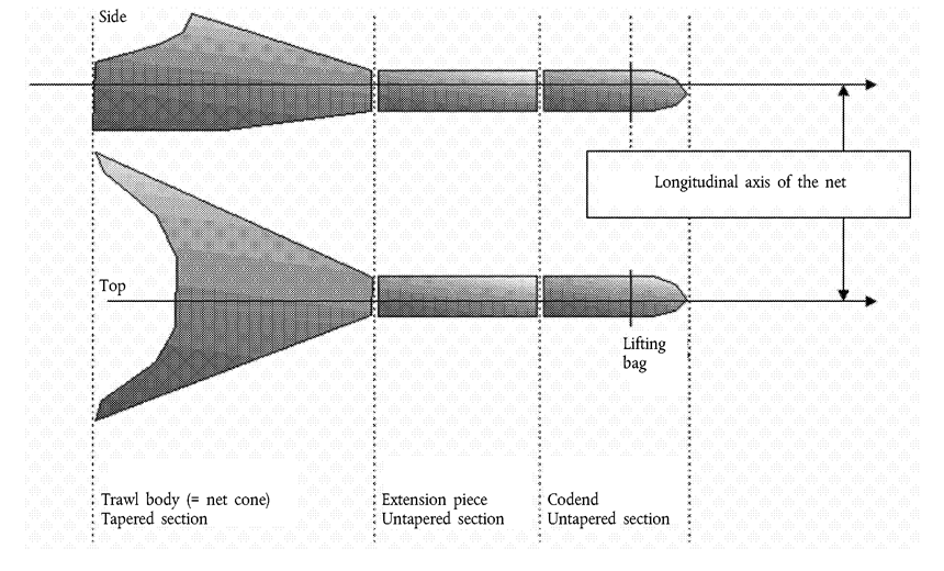
‘diamond mesh’ means a mesh as shown in figure 1 of Annex II, composed of four bars of the same length where the two diagonals of the mesh are perpendicular and one diagonal is parallel to the longitudinal axis of the net as shown in figure 2 of Annex II;
‘square mesh’ means a quadrilateral mesh composed of two sets of parallel bars of the same length, where one set is parallel to, and the other is at right angles to the longitudinal axis of the net;
‘T90 mesh’ means a diamond mesh from knotted netting, as shown in figure 1 of Annex II, mounted so that the T-direction of the netting is parallel to the longitudinal axis of the net.
CHAPTER IIU.K.EC GAUGES
Article 3U.K.Mesh gauge and twine thickness gauges
1.Community and national inspectors shall use the mesh gauge and twine thickness gauges which comply with the provisions of this Regulation for the determination of the mesh size and the twine thickness of fishing nets when conducting fishery inspections.
2.The technical specifications applying to the mesh gauge are set out in Annex III.
3.The technical specifications applying to twine thickness gauges are set out in Annex IV.
4.The mesh gauge and twine thickness gauges referred to in paragraph 1 shall be marked ‘EC gauge’ and certified by the manufacturer as complying with the technical specification referred in paragraphs 2 and 3 respectively.
5.The mesh gauge and twine thickness gauges sold or distributed for use by entities or persons other than national fisheries authorities shall not be marked ‘EC gauge’.
Article 4U.K.Calibration instruments for the mesh gauge
The calibrated test weights and calibrated test measuring plate provided for in figure 1 of Annex V shall be certified by the competent national authorities and marked ‘EC’.
Article 5U.K.Testing of the mesh gauges
The accuracy of the mesh gauge shall be verified by:
inserting the jaws of the gauge into slots of the calibrated test plate as provided for in figure 1 of Annex V;
hanging the calibrated test weights on the fixed jaw, as provided for in figure 2 of Annex V.
CHAPTER IIIU.K.DETERMINATION OF MESH SIZE
Article 6U.K.Selection of meshes in active gear
1.The inspector shall select a series of 20 consecutive meshes from the net, chosen in the following direction:
(a)for diamond and square meshes, in the direction of the longitudinal axis of the net;
(b)for T90 meshes, perpendicular to the direction of the longitudinal axis of the net.
2.Meshes less than three meshes from the selvedge, lacings, ropes or cod line shall not be measured. That distance shall be measured perpendicular to the lacings, ropes or cod line with the net stretched in the direction of that measurement. Meshes which are broken or have been repaired or have attachments to the net fixed at that mesh shall not be measured.
3.By way of derogation from paragraph 1, the meshes to be measured need not to be consecutive if the application of paragraph 2 prevents it.
Article 7U.K.Selection of meshes in passive gear
1.The inspector shall select 20 meshes from the fishing net. In the case of different mesh sizes in the fishing net, the meshes shall be selected from the part of the fishing net having the smallest meshes.
2.When selecting meshes in accordance with paragraph 1, the following meshes shall not be included:
(a)meshes at the top, bottom or side of a net selvedge;
(b)meshes within three meshes of lacings and ropes;
(c)meshes that have been broken or have been repaired.
Article 8U.K.General provisions on the preparation and operation of mesh gauges
The mesh gauge shall be:
prepared in accordance with Annex VI;
operated in accordance with Annex VII.
Article 9U.K.Operation of the mesh gauge for measuring diamond and T90 meshes
When measuring diamond and T90 meshes in:
knotted and knotless netting when the N-direction can be determined, the netting shall be stretched in the N-direction of the meshes, as shown in Annex VII;
knotless netting when the N-direction cannot be determined, the longest axis of the mesh shall be measured.
Article 10U.K.Operation of the mesh gauge for measuring square meshes
1.When measuring a square mesh panel, the netting shall be stretched first in one diagonal direction and then in the other diagonal direction of the mesh, as shown in Annex VIII.
2.The procedure laid down in Annex VI shall apply to the measurement of each diagonal direction of the square mesh.
Article 11U.K.Measurement conditions
Meshes shall be measured only when wet and unfrozen.
Article 12U.K.Measurement of the size of each selected mesh
1.The size of each mesh shall be the distance between the outside edges of the jaws of the gauge at the point where the movable jaw is stopped.
2.Where there is a difference in measurement between the diagonals of an individual square mesh, then the larger diagonal shall be used.
Article 13U.K.Determination of the mesh size of the net
The mesh size of the net shall be determined as the mean value, displayed by the gauge, of the series of 20 selected meshes.
Article 14U.K.Determination of the mesh size in case of disputes
1.If the master of a fishing vessel disputes the result of the determination of the mesh size carried out in accordance with Article 13, 20 meshes shall be selected and measured in another part of the fishing net in accordance with Articles 6 to 12.
2.The mesh size shall then be redetermined as the mean value, displayed by the gauge, of all 40 meshes measured. The displayed result of the gauge shall be final.
CHAPTER IVU.K.ASSESSING TWINE THICKNESS
Article 15U.K.General provisions on the selection of twines
1.The inspector shall select meshes from any part of the fishing net which is subject to a maximum permitted twine thickness.
2.Twines within a mesh that are broken or have been repaired shall not be selected.
Article 16U.K.Selection of twines in diamond mesh netting
Twines in diamond mesh netting shall be selected in the following way, as shown in Annex VIII:
in the case of single twine netting, the twine on opposite sides of 10 meshes shall be selected;
in the case of double twine netting, each strand of twine on opposite sides of five meshes shall be selected.
Article 17U.K.Selection of twines in square mesh netting
Twines in square mesh netting shall be selected in the following way, as shown in Annex VIII:
in the case of single twine netting, the twine on only one side of 20 meshes shall be selected, with the same side being selected in each mesh;
in the case of double twine netting, each strand of twine on only one side of 10 meshes shall be assessed, with the same side being selected in each mesh.
Article 18U.K.Selection of the twine thickness gauge
A gauge with a circular hole with a diameter equal to the maximum twine thickness permitted for the part of the net considered shall be used by the inspector.
Article 19U.K.Assessment conditions
Twines shall be assessed when unfrozen.
Article 20U.K.Assessment of the thickness of each selected twine
When the thickness of the twine prevents the closure of the jaws of the gauge or the twine does not pass easily through the hole when the jaws are closed, the assessment of the thickness of a twine shall be noted by the inspector as a negative assessment (–).
Article 21U.K.Assessing twine thickness
1.If more than five negative assessments (–) of the 20 twines selected are noted in accordance with Article 20, the inspector shall again select and assess a further 20 twines in accordance with Articles 15 to 20.
2.If more than 10 negative assessments (–) of the total 40 twines selected are found, the twine thickness shall be determined as exceeding the maximum twine thickness permitted for that part of the fishing net.
Article 22U.K.Assessment of twine thickness in case of disputes
1.If the master of the vessel disputes the result of the assessment of the twine thickness carried out in accordance with Article 21, the provisions of paragraph 2 of this Article shall apply.
2.The inspector shall again select and assess 20 different twines in the same part of the fishing net. If more than five negative assessments (–) of the total 20 twines selected are found, the twine thickness shall be determined as exceeding the maximum twine thickness permitted for that part of the fishing net. The result of that assessment shall be final.
CHAPTER VU.K.FINAL PROVISIONS
Article 23U.K.Repeal
1.Regulation (EC) No 129/2003 is repealed.
2.Reference to the provisions of the Regulation (EC) No 129/2003 shall be construed as reference to the present Regulation and read in accordance with the correlation table in Annex IX.
Article 24U.K.Transitional provisions
1.For a transitional period until 1 September 2009 a Member State may continue to apply, in the waters under its sovereignty or jurisdiction the methods for determining the mesh size and assessing the thickness of twine of fishing nets which are in conformity with Regulation (EC) No 129/2003.
2.If a Member State intends to apply in the waters under its sovereignty or jurisdiction the methods for determining the mesh size and assessing the twine thickness which are in conformity with Regulation (EC) No 129/2003 for a transitional period until 1 September 2009, it shall immediately inform the Commission thereof and publish this information on its official website.
Article 25U.K.Entry into force
This Regulation shall enter into force on the third day following its publication in the Official Journal of the European Union.
This Regulation shall be binding in its entirety and directly applicable in all Member States.
Done at Brussels, 10 June 2008.
For the Commission
Joe Borg
Member of the Commission
ANNEX IU.K.Mesh size and N-direction and T-direction of netting twine
FigureU.K.

ANNEX IIU.K.
Diamond knotted netting and T90 nettingU.K.
Figure 1
The direction of run of the netting twine in a standard diamond knotted net (A) and in a net turned 90° (B) is shown below.

Longitudinal axis of the netU.K.
ANNEX IIIU.K.Technical specifications of the mesh gauge
1.The mesh gauge shall:U.K.
automatically apply a longitudinal measuring force when measuring the mesh size of fishing nets;
have two jaws, one fixed and one movable, each 2 mm thick with rounded edges with a radius of 1 mm to ensure that the jaws slip easily over the twine as shown in figure below;
be electrically driven or if battery powered it shall be capable of making 1 000 consecutive mesh measurements before requiring to be recharged;
be able to apply selected longitudinal forces, in the range 5 to 180 N, to the meshes with a precision of 1 N;
have a built-in system for measuring the applied force;
be capable to stretch a mesh at a constant speed of 300 ± 30 mm/min by the movable jaw;
be able to measure meshes from 10 to 300 mm and have detachable jaws for use on small and large meshes;
have a measurement precision of 1 mm;
have a structure which is rigid and shall not be distorted under load;
be light yet robust and should weigh no more than 2,5 kg;
be made of materials resistant to corrosion under marine conditions;
be water resistant and unaffected by dust to standard IP56(3);
be stable in operation over a temperature range of – 10 to + 45 °C;
be able to withstand temperatures between – 30 and 70 °C during storage and transportation;
be controlled by software which should provide a menu of functions and enable the gauge to self-test the electronic and mechanical parts when started;
display that the gauge is ready for use and if not, display an error message, close down and cease operating;
be possible to operate with one hand and the functions must be accessed via external buttons;
show data on an integral display and present each measurement, the number of measurements made in a series, and the mean value in millimetres;
store the data of at least 1 000 measurements in its memory and it must be possible to transmit data to a computer;
contain a function to calculate the mean mesh size rounded to the nearest 0,1 mm;
incorporate software having a function to automatically select the largest diagonal of each mesh to calculate the mean mesh size of the square mesh netting;
save the data of all measurements made.
2.Some netting creeps under load. The gauge must respond to this condition by reapplying the fixed force, requiring an algorithm in the controlling software, as described in the Appendix.U.K.
Figure(These drawings are for illustrative purposes only)U.K.

Appendix to Annex IIIMeasurement algorithm
To allow for creep in a stretched mesh:
extend the movable jaw into the mesh at a constant speed of 300 ± 30 mm/min(4), until the measurement force is reached;
stop the motor and wait for 1 second;
if the force drops below 80 % of the pre-set measurement force, extend the movable jaw into the mesh until the measurement force is reached once more.
ANNEX IVU.K.Technical specifications of the twine thickness gauge
Gauges for assessing the thickness of twine shall:
be made of durable, non-corrosive material able to withstand a harsh marine environment and shall be manufactured in accordance with the drawings shown in the figure below;
have edges around the circumference of each side of the circular hole for assessing the thickness of the twine (the hole) rounded to avoid abrasion when the twine is pulled through the hole to test legality;
be constructed with the nose of the pliers rounded to facilitate inserting the jaws between double twines;
have jaws with parallel action that are sufficiently strong to prevent deformation of the jaws during any reasonable use, bearing in mind that the jaws have to be squeezed closed with manual force during every measurement;
have the inside faces of the jaws milled to leave a 0,5 mm gap for a distance of 1 mm either side of the hole when the jaws are closed in order to avoid single filaments of material protruding from braided or twisted construction being trapped in the flat surfaces of the jaws on each side of the hole in which the twine is seated;
have, when the jaws are closed, the diameter of the circular hole marked in millimetres on one of the jaws, adjacent to the hole; the jaws are closed when the surface of both internal sides of the jaws touch each other and are flush;
have both the handle and the jaws marked ‘EC gauge’;
have a tolerance for the hole diameter of 0 + 0,1 mm;
be conveniently portable such that a set of four (4 mm, 5 mm, 6 mm, and 8 mm) gauges may be carried by an inspector during vessel to vessel transfer at sea;
if gauges are of different sizes, be easily identifiable;
be easy to insert between double twine. After the gauge has been inserted into position, it shall be capable of easy operation with one hand.
FigureTwine-measuring pliers assemblyU.K.


ANNEX VU.K.Calibration and testing of the mesh gauge
A.Verification of length measurementU.K.
The verification of length measurement shall be performed by inserting the jaws of the gauge to be used during the inspection, into slots of different lengths in the calibrated rigid test plate. This can be done at any time.

B.Verification of force measurementU.K.
The verification of force measurement shall be performed by hanging calibrated weights on the fixed jaw containing the load cell, with the gauge held vertical and secure. The weights shall have the following values: 10, 20, 50 and 125 N. The weights can only be used under stable conditions.
ANNEX VIU.K.Preparation of the mesh gauge
1.The inspector shall:U.K.
select the appropriate size of jaw for the meshes to be measured;
ensure that the jaws are clean;
check that the gauge completes the self-test satisfactorily;
select the measuring force to be applied as follows:
for active gear:
20 N for mesh sizes < 35 mm,
50 N for mesh sizes ≥ 35 mm and < 55 mm,
125 N for mesh sizes ≥ 55 mm;
for passive gear:
10 N for all mesh sizes;
verify the jaw type setting. The default setting is ‘Normal’. If small or large jaws are used, the inspector shall enter the menu and change the jaw type setting accordingly.
2.When the activities set out in point 1 are completed the gauge is then ready to undertake mesh measurements.U.K.
ANNEX VIIU.K.Operation of the mesh gauge for inspection
When measuring the meshes the inspector shall:

ANNEX VIIIU.K.Twines in diamond and square mesh netting
FigureU.K.

ANNEX IXU.K.
Correlation table
| Regulation (EC) No 129/2003 | This Regulation |
|---|---|
| — | Article 1 |
| Article 1 | Article 2 |
| Article 2(1) | Article 3(2) |
| Article 2(2) | Article 3(4) |
| Article 3(1) | Article 9 |
| Article 3(2) | — |
| Article 3(3) | — |
| Article 4(1) | Article 10(1) |
| Article 4(2) | Article 10(2) |
| Article 5(1) | Article 6(1) |
| Article 5(2) | Article 6(2) |
| Article 5(3) | Article 6(3) |
| Article 6(1) | Article 11 |
| Article 6(2) | Article 12(1) |
| Article 6(3) | Article 12(2) |
| Article 7 | Article 13 |
| Article 8 | — |
| Article 9 | Article 14 |
| Article 10(1) | Article 3(2) |
| Article 10(2) | Article 3(2) |
| Article 10(3) | Article 3(4) |
| Article 10(4) | Article 3(2) |
| Article 10(5) | Article 3(2) |
| Article 11(1) | Article 7(1) |
| Article 11(2) | Article 7(2) |
| Article 12(1) | Article 11 |
| Article 12(2) | Article 8 |
| Article 13 | Article 13 |
| Article 14 | Article 6 |
| Article 15 | Article 14 |
| Article 16(1) | Article 3(3) |
| Article 16(2) | Article 3(3) |
| Article 16(3) | Article 3(4) |
| Article 17(1) | Article 15(1) |
| Article 17(2) | Article 15(2) |
| Article 17(3) | — |
| Article 18(1) | Article 19 |
| Article 18(2) | Article 16 |
| Article 18(3) | Article 17 |
| Article 19(1) | Article 20 |
| Article 19(2) | Article 21(1) |
| Article 19(3) | Article 21(2) |
| Article 20 | Article 22 |
OJ L 125, 27.4.1998, p. 1. Regulation as last amended by Regulation (EC) No 2166/2005 (OJ L 345, 28.12.2005, p. 5).
Internal protection (IP) codes are specified in the international standard of the International Electrotechnical Commission (IEC) 60529.
Speed of the movable jaw during the stretching of the mesh. The unloaded speed of the movable jaw can be higher.