Appendix 2
Test method for determining reflectivity
1.DEFINITIONSU.K.
1.1.CIE standard illuminate A(1): Colorimetric illuminate, respecting the full radiator at T68 = 2 855,6 K.U.K.
1.2.CIE standard source A(1): Gas-filled tungsten filament lamp operating at a correlated colour temperature of T68= 2 855,6 K.U.K.
1.3.CIE 1931 standard colorimetric observer(1): Receptor of radiation whose colorimetric characteristics correspond to the spectral tristimulus values  (λ),
(λ),  (λ),
(λ),  (λ) (see table).U.K.
1.4.CIE spectral tristimulus values(1): Tristimulus values of the spectral components of an equi-energy spectrum in the CIE (XYZ) system.U.K.
1.5.Photopic vision(1): Vision by the normal eye when it is adapted to levels of luminance of at least several cd/m2.U.K.
2.APPARATUSU.K.
2.1.GeneralU.K.
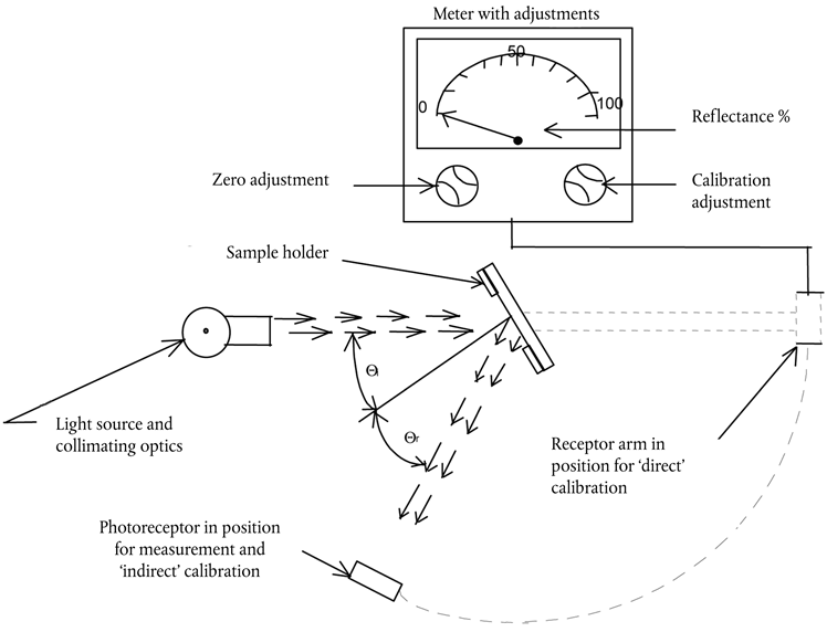
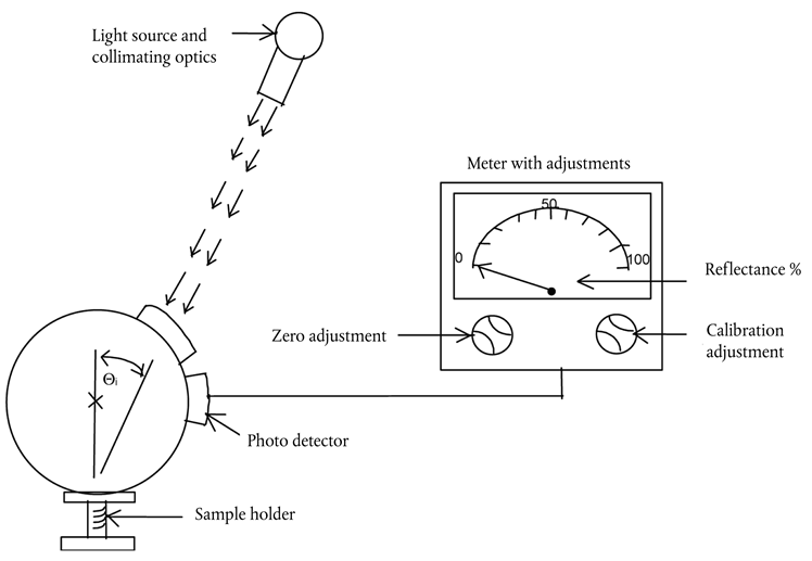
The apparatus shall consist of a light source, a holder for the test sample, a receiver unit with a photodetector and an indicating meter (see Figure 4), and means of eliminating the effects of extraneous light.
The receiver may incorporate a light-integrating sphere to facilitate measuring the reflectance of non-flat (convex) mirrors (see Figure 5).
2.2.Spectral characteristics of light source and receiverU.K.
The light source shall consist of a CIE standard source A and associated optics to provide a near-collimated light beam. A voltage stabiliser is recommended in order to maintain a fixed lamp voltage during instrument operation.
The receiver shall have a photodetector with a spectral response proportional to the photopic luminosity function of the CIE (1931) standard colorimetric observer (see table). Any other combination of illuminate-filter-receptor giving the overall equivalent of CIE standard illuminate A and photopic vision may be used. When an integrating sphere is used in the receiver, the interior surface of the sphere shall be coated with a matt (diffusive) spectrally non-selective white coating.
2.3.Geometrical conditionsU.K.
The angle of the incident beam (θ) should preferably be 0,44 ± 0,09 rad (25 ± 5 °) from the perpendicular to the test surface and shall not exceed the upper limit of the tolerance (i.e. 0,53 rad or 30 °). The axis of the receptor shall make an angle (θ) with this perpendicular equal to that of the incident beam (see Figure 4). The incident beam upon arrival at the test surface shall have a diameter of not less than 13 mm (0,5 in.). The reflected beam shall not be wider than the sensitive area of the photodetector, shall not cover less than 50 % of such area, and as nearly as possible shall cover the same area segment as used during instrument calibration.
When an integrating sphere is used in the receiver section, the sphere shall have a minimum diameter of 127 mm (5 in.). The sample and incident beam apertures in the sphere wall shall be of such a size as to admit the entire incident and reflected light beams. The photodetector shall be so located as not to receive direct light from either the incident or the reflected beam.
2.4.Electrical characteristics of the photodetector-indicator unitU.K.
The photodetector output as read on the indicating meter shall be a linear function of the light intensity of the photosensitive area. Means (electrical and/or optical) shall be provided to facilitate zeroing and calibration adjustments. Such means shall not affect the linearity or the spectral characteristics of the instrument. The accuracy of the receptor-indicator unit shall be within ± 2 % of full scale, or ± 10 % of the magnitude of the reading, whichever is the smaller.
2.5.Sample holderU.K.
The mechanism shall be capable of locating the test sample so that the axes of the source arm and receptor intersect at the reflecting surface. The reflecting surface may lie within or at either face of the mirror sample, depending on whether it is a first-surface, second-surface or prismatic ‘flip’-type mirror.
3.PROCEDUREU.K.
3.1.Direct calibration methodU.K.
In the direct calibration method, air is used as the reference standard. This method is applicable for those instruments, which are so constructed as to permit calibration at the 100 % point by swinging the receiver to a position directly on the axis of the light source (see Figure 4).
It may be desired in some cases (such as when measuring low-reflectivity surfaces) to use an intermediate calibration point (between 0 and 100 % on the scale) with this method. In these cases, a neutral density filter of known transmittance shall be inserted in the optical path, and the calibration control shall then be adjusted until the meter reads the percentage transmission of the neutral density filter. This filter shall be removed before reflectivity measurements are performed.
3.2.Indirect calibration methodU.K.
The indirect calibration method is applicable in the case of instruments with fixed source and receiver geometry. A properly calibrated and maintained reflectance standard is required. This reference standard should preferably be a flat mirror with a reflectance value as near as possible to that of the test samples.
3.3.Flat mirror measurementU.K.
The reflectance of flat mirror samples can be measured on instruments employing either the direct or the indirect calibration method. The reflectance value is read directly from the indicating meter.
3.4.Non-flat (convex) mirror measurementU.K.
Measurement of the reflectance of non-flat (convex) mirrors requires the use of instruments which incorporate an integrating sphere in the receiver unit (see Figure 5). If the instrument-indicating meter indicates ne divisions with a standard mirror of E % reflectance, then, with a mirror of unknown reflectance, nx divisions will correspond to a reflectance of X %, in accordance with the formula:

Spectral tristimulus values for the CIE 1931 standard colorimetric observer(2) U.K.
This table is taken from CIE publication 50 (45) (1970)
| a Changed in 1966 (from 3 to 2) | |||
| λnm |  (λ) (λ) |  (λ) (λ) |  (λ) (λ) |
|---|---|---|---|
| 380 | 0,0014 | 0,0 | 0,0065 |
| 390 | 0,0042 | 0,0001 | 0,0201 |
| 400 | 0,0143 | 0,0004 | 0,0679 |
| 410 | 0,0435 | 0,0012 | 0,2074 |
| 420 | 0,1344 | 0,004 | 0,6456 |
| 430 | 0,2839 | 0,0116 | 1,3856 |
| 440 | 0,3483 | 0,023 | 1,7471 |
| 450 | 0,3362 | 0,038 | 1,7721 |
| 460 | 0,2908 | 0,06 | 1,6692 |
| 470 | 0,1954 | 0,091 | 1,2876 |
| 480 | 0,0956 | 0,139 | 0,813 |
| 490 | 0,032 | 0,208 | 0,4652 |
| 500 | 0,0049 | 0,323 | 0,272 |
| 510 | 0,0093 | 0,503 | 0,1582 |
| 520 | 0,0633 | 0,71 | 0,0782 |
| 530 | 0,1655 | 0,862 | 0,0422 |
| 540 | 0,2904 | 0,954 | 0,0203 |
| 550 | 0,4334 | 0,995 | 0,0087 |
| 560 | 0,5945 | 0,995 | 0,0039 |
| 570 | 0,7621 | 0,952 | 0,0021 |
| 580 | 0,9163 | 0,87 | 0,0017 |
| 590 | 1,0263 | 0,757 | 0,0011 |
| 600 | 1,0622 | 0,631 | 0,0008 |
| 610 | 1,0026 | 0,503 | 0,0003 |
| 620 | 0,8544 | 0,381 | 0,0002 |
| 630 | 0,6424 | 0,265 | 0,0 |
| 640 | 0,4479 | 0,175 | 0,0 |
| 650 | 0,2835 | 0,107 | 0,0 |
| 660 | 0,1649 | 0,061 | 0,0 |
| 670 | 0,0874 | 0,032 | 0,0 |
| 680 | 0,0468 | 0,017 | 0,0 |
| 690 | 0,0227 | 0,0082 | 0,0 |
| 700 | 0,0114 | 0,0041 | 0,0 |
| 710 | 0,0058 | 0,0021 | 0,0 |
| 720 | 0,0029 | 0,001 | 0,0 |
| 730 | 0,0014 | 0,0005 | 0,0 |
| 740 | 0,0007 | 0,0002a | 0,0 |
| 750 | 0,0003 | 0,0001 | 0,0 |
| 760 | 0,0002 | 0,0001 | 0,0 |
| 770 | 0,0001 | 0,0 | 0,0 |
| 780 | 0,0 | 0,0 | 0,0 |
